A Coordinated Electric System Interconnection Review—the utility’s deep-dive on technical and cost impacts of your project.
Challenge: Frequent false tripping using conventional electromechanical relays
Solution: SEL-487E integration with multi-terminal differential protection and dynamic inrush restraint
Result: 90% reduction in false trips, saving over $250,000 in downtime
The three operating regions you have to design to
| Device | Output vs voltage | Response | Best suited to | Main limitations |
|---|---|---|---|---|
| Mechanically switched capacitor or reactor | Proportional to voltage squared | Seconds; discrete steps; limited switching operations per day | Steady-state reactive supply, voltage profile, loss reduction | No dynamic capability; step voltage change on switching; capability collapses when most needed |
| Static var compensator | Capacitive branches proportional to voltage squared | A few cycles; continuously controllable | Continuous control where cost matters and deep voltage support is not the driver | Square-law capability loss; harmonic filters are part of the plant and interact with the network |
| STATCOM | Approximately proportional to voltage — constant current capability | One to two cycles closed loop; converter response faster still | Voltage stability margin, weak interconnections, fast disturbance recovery, flicker and unbalance compensation | Higher capital cost; converter losses; adds a converter and its control dynamics to the network |
| Synchronous condenser | Governed by machine capability and excitation | Excitation response in the hundreds of milliseconds; inherent inertial response instantaneous | System strength and inertia, short-circuit contribution, black start support | Rotating plant with maintenance and losses; slower controlled response than a converter |
| STATCOM with energy storage | Reactive as a STATCOM, plus real power within the storage rating | As STATCOM for reactive; real power limited by storage | Where a real power deficiency is part of the problem | Cost and complexity of the storage; different failure and maintenance profile |
| Stage | Keentel scope | Outcome |
|---|---|---|
| Screening | Series-compensation proximity, radial contingency review, UIF and short-circuit ratio screening, frequency scans | Early identification of which SSO types apply |
| Detailed studies | PSCAD/EMTDC EMT studies with vendor real-code models, impedance-based and frequency-scan analysis | Clear evidence of stability margins or risk |
| Model quality | EMT model review, benchmarking against positive-sequence models, model acceptance support | Models that system operators accept |
| Mitigation | Control retuning recommendations with vendors, SSDC and bypass logic requirements, protection and monitoring specifications | Practical, coordinated solutions |
| Interconnection support | SSR and SSO study reports for ISO and utility requirements, response to reviewer comments | Fewer delays in the interconnection process |
Resilience: designing CDUs to the facility Tier objective
Liquid cooling makes heat removal more critical, not less. Cold plates hold only seconds of thermal buffer. If TCS flow stops, processors throttle or shut down very quickly. Resilience design must therefore cover:
- Pump redundancy: N+1 pumps at minimum, with automatic changeover.
- CDU redundancy: N+1 CDUs on a common TCS header, or 2N CDUs serving A and B manifolds for fault-tolerant designs.
- Power to CDUs: dual-corded CDUs fed from A and B sources, with pumps and controls on UPS power so coolant keeps flowing through a utility failure and generator start. This is the liquid-cooling equivalent of continuous cooling.
- Facility water continuity: chilled water or condenser water must also continue, through thermal storage, UPS-backed pumps or a high enough FWS temperature that the TCS can coast on stored thermal mass for the transfer period.
- Concurrent maintainability: isolation valves so any CDU, pump, filter or manifold section can be serviced without stopping the others.
- Leak management: leak detection, drip trays, automatic isolation valves and procedures for fluid spills.
Electrical engineering considerations
CDUs and liquid-cooling plants are electrical loads with their own design requirements:
- Pump motors and VFDs. Large CDUs use variable-frequency drives on their pump motors. These introduce harmonic current that must be included in the facility's harmonic study and IEEE 519 evaluation.
- Critical mechanical load on UPS. Putting CDU pumps on UPS increases UPS and battery sizing. The mechanical UPS load must be included in redundancy and ride-through calculations.
- Feeder and protection design. Dual feeds, automatic transfer, selective coordination and arc-flash labelling apply to CDU power distribution just as they do to IT power.
- Generator transient response. CDU pumps restarting together after a transfer create motor inrush on the generators. Staged restarts and soft acceleration reduce the step load.
- Load dynamics. AI training loads can swing rapidly between high and low power. Cooling controls must track those swings without temperature overshoot, and electrical systems must handle both the IT and the cooling load changes.
Commissioning a liquid-cooled data hall
- Flush and clean the TCS piping and manifolds to the specified cleanliness, using high-purity flush water.
- Fill and vent with the specified coolant, verifying glycol concentration and chemistry.
- Pressure test for leaks at design and test pressures, including quick-disconnect fittings.
- Verify sensors and controls: flow meters, temperature sensors, pressure transmitters, leak detection and BMS points.
- Load test with heat load banks connected through the cold-plate interfaces or rack manifolds, across the operating range.
- Prove the heat balance on both loops at several load steps, and the approach temperature against the design.
- Test failure scenarios: pump failure, CDU failure, power transfer to generator, valve failure and loss of facility water, confirming temperatures stay within the IT vendor's limits.
How Keentel Engineering helps
Keentel Engineering supports data center owners, developers and EPCs with the electrical engineering that liquid-cooled facilities depend on, and coordinates with the mechanical engineer of record and cooling vendors on the integrated design.
Why Can a Generator Trip on Reverse Power? An Engineering Guide to ANSI 32 Protection for US Plants
October 20, 2026 | Blog
Part A — Reverse Power Protection at a Glance
A synchronous generator connected to the US grid does not stop turning when its prime mover stops pushing. The rest of the interconnection holds it at synchronous speed. If the turbine or engine loses its steam, water, fuel or combustion, the electrical machine simply changes roles: instead of converting mechanical power into electrical power, it draws active power from the grid and drives the prime mover like a motor. This is called motoring, and the generator itself is usually perfectly comfortable doing it. The prime mover often is not.
Reverse power protection — ANSI device 32 — detects active power flowing into the generator and trips the unit, or acts as a permissive in a sequential tripping scheme, before the turbine or engine is damaged.
Normal generation versus reverse power
| Condition | Mechanical input | Active power flow | Machine operates as | Reactive power |
|---|---|---|---|---|
| Normal generation | Steam, water, fuel or gas drives the shaft | Generator to grid | Generator | Exported or absorbed, set by excitation |
| Reverse power (motoring) | Lost or reduced below no-load losses | Grid to generator | Synchronous motor driving the prime mover | Still set by excitation; often still exported |
What motoring does to each type of prime mover
| Prime mover | Typical motoring power (% of rating) | Main concern |
|---|---|---|
| Condensing steam turbine | About 0.5% to 3% | Overheating of low-pressure blades from windage when steam flow stops |
| Hydro turbine | About 0.2% to 2% with blades out of water; much higher with water present | Cavitation and blade damage at low flow; draft tube problems |
| Combustion turbine (single shaft) | About 10% to 50% | Large power draw; gearbox and compressor loading |
| Reciprocating diesel or gas engine | About 5% to 25% | Unburned fuel accumulation, fire or explosion risk, mechanical damage |
Values vary by design; manufacturer data governs every setting.
Keentel's worked example in one line
For a 600 MVA, 22 kV steam turbine-generator connected through a 22/345 kV generator step-up (GSU) transformer, a motoring power of 1.5% is about 9 MW. A 32 element set at 0.5% (3 MW) sees only about 4.1 secondary watts at pickup — small enough that current and voltage transformer phase-angle errors can create measurement errors of 1 to 3 MW when the unit is exporting reactive power.
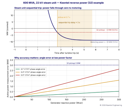
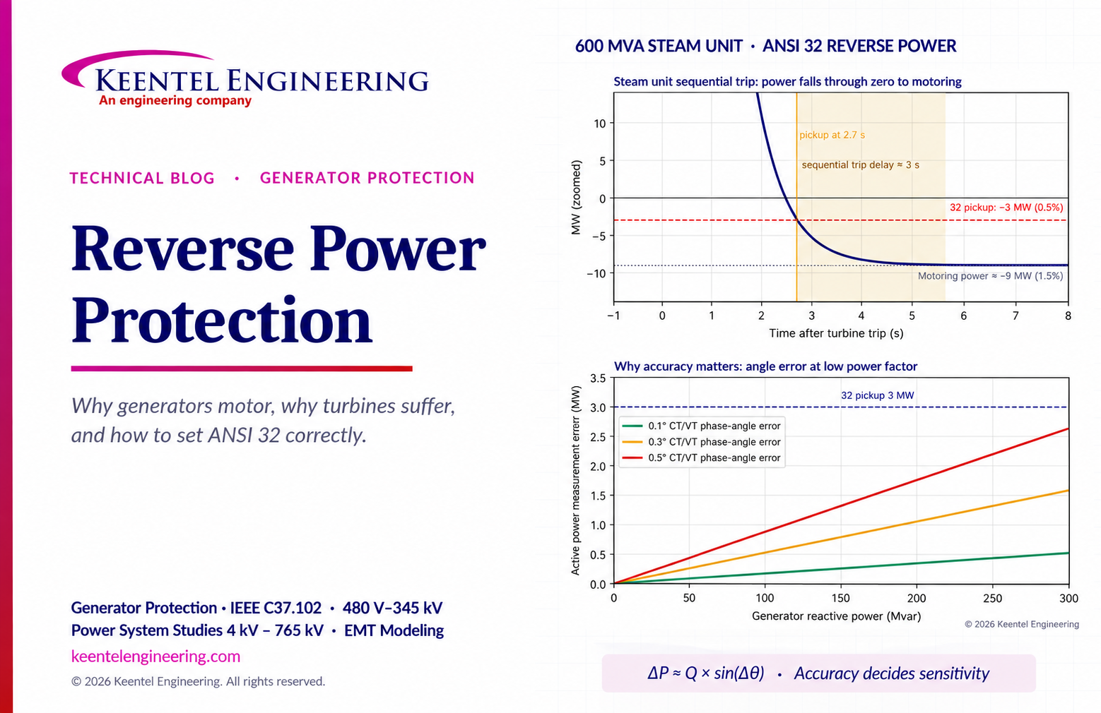
Figure 1. Top: after a steam turbine trip, generator power falls through zero to the motoring level; the reverse power element picks up and trips the breaker after a short sequential-trip delay. Bottom: active power measurement error from small CT and VT phase-angle errors increases with reactive power, approaching the pickup setting.
Reverse power protection is turbine protection more than generator protection. The setting has to reflect the actual prime mover, the measurement accuracy, and the way the plant trips its units.
Part B — Why Can a Generator Trip on Reverse Power? An Engineering Guide to ANSI 32 Protection for US Plants
1. Why the generator keeps turning
In a large interconnected system, each synchronous generator is locked to every other synchronous machine through the transmission network. The electrical torque on the rotor depends on the angle between the rotor and the system:
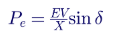
When mechanical power from the turbine falls, the rotor angle δ decreases. If mechanical power falls below the machine's no-load losses, δ becomes negative and Pe becomes negative — the machine draws power from the system. Because the system is far larger than the unit, it holds the frequency and the machine continues to rotate at synchronous speed. Nothing about the electrical machine requires it to stop.
The swing equation describes the transition:
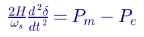
After a turbine trip, Pm falls toward zero over a time determined by valve closure and the energy stored in steam, gas or water passages. The rotor angle slides back, electrical power falls through zero, and the machine settles at a small negative power equal to the losses needed to drive the turbine.
2. What causes reverse power
| Cause | Example |
|---|---|
| Turbine trip without generator breaker trip | Steam stop valves close on a turbine protection trip while the generator breaker remains closed |
| Loss of fuel | Gas supply pressure loss on a combustion turbine; diesel fuel starvation |
| Loss of water | Wicket gates close on a hydro unit, or headwater is lost |
| Governor or control failure | Speed reference driven low, load reference lost |
| Synchronizing error | Breaker closed with the generator slightly slower than the system |
| Load rejection on parallel units | Load sharing problems on industrial or microgrid buses |
| Intentional shutdown | Unit unloaded to zero before opening the breaker, with slight overshoot into reverse power |
Not all causes are faults. In many US plants, reverse power is part of every normal shutdown: the turbine is tripped first, and the generator breaker opens only after power has reversed. This is the sequential tripping scheme discussed in Section 7.
3. Why motoring damages prime movers
3.1 Steam turbines
When steam flow stops, the turbine blades — especially the long last-stage blades in the low-pressure section — churn the remaining steam. This windage heats the blades, which can reach temperatures that cause distortion, rubbing, erosion or loss of blade material strength. The damage is time-dependent: many manufacturers permit motoring for a limited time, but not indefinitely. Condensing steam units have very low motoring power, often below 1% of rating, because the vacuum in the condenser greatly reduces windage losses, which is exactly what makes them hard to detect.
3.2 Hydro turbines
With the wicket gates closed and the runner still in water, motoring power may be relatively high, and cavitation or rough operation can damage the runner and draft tube. When the water is depressed below the runner with compressed air — as for synchronous condenser operation — motoring power falls to a small fraction of a percent. Some hydro units are intentionally operated as synchronous condensers this way; their protection must distinguish intended condensing mode from unintended motoring.
3.3 Combustion turbines
A single-shaft combustion turbine drives its own compressor, so motoring requires a large amount of power — often 10% to 50% of rating. Motoring is easy to detect, and the main risks are to the gearbox and other mechanical components and the large, unwanted power draw. Aeroderivative and multi-shaft designs differ significantly; the manufacturer's data is essential.
3.4 Reciprocating engines
Diesel and natural gas engines at data centers, hospitals, industrial plants and microgrids typically need 5% to 25% of rating to motor. Motoring can cause unburned fuel to accumulate in the exhaust system, creating fire or explosion risk when combustion resumes, and can stress crankshafts, bearings and couplings. Emergency and standby generators that parallel with the utility for closed-transition transfer, peak shaving or testing need reliable reverse power protection.
3.5 Summary of typical settings guidance
| Prime mover | Typical motoring power | Typical 32 pickup | Typical time delay |
|---|---|---|---|
| Condensing steam turbine | 0.5% to 3% | Below motoring power, often 0.5% or less | 5 s to 30 s standalone; short delay in sequential trip |
| Hydro (runner in water) | 2% or more | Below motoring power | 10 s to 30 s |
| Hydro (water depressed) | 0.2% to 2% | Requires very sensitive setting; coordinate with condensing mode logic | 10 s to 30 s |
| Combustion turbine | 10% to 50% | Typically 5% to 10% of rating or per manufacturer | 5 s to 30 s |
| Reciprocating engine | 5% to 25% | Typically 5% to 10% of rating or per manufacturer | 2 s to 10 s |
These ranges reflect common industry guidance in IEEE C37.102 and manufacturer practice; actual settings must be based on the specific machine's data, the relay's accuracy and the plant's operating philosophy.
4. How a reverse power element measures
4.1 Three-phase active power
Modern numerical relays calculate three-phase active power from CT and VT secondary quantities:

or, for balanced conditions, P = √3 VLL IL cos φ. The element compares the measured power with a negative setting and operates when power flows into the machine for longer than the time delay.
4.2 Converting primary settings to secondary watts
The secondary pickup in watts is:
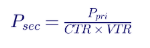
For the 600 MVA, 22 kV unit with a 20,000:5 CT (CTR = 4,000) and a 22,000:120 V VT (VTR = 183.3):
| Quantity | Primary | Secondary |
|---|---|---|
| Rated apparent power | 600 MVA | about 818 VA (three-phase) |
| Rated current | 15,746 A | 3.94 A |
| Motoring power (1.5%) | 9 MW | about 12.3 W |
| 32 pickup (0.5%) | 3 MW | about 4.1 W |
A pickup of about 4 secondary watts out of 818 VA is a very small quantity to measure reliably, especially with significant reactive current flowing.
4.3 The low power factor problem
During motoring, the generator usually continues to export or absorb reactive power because its excitation system is still in service. The active power being measured is tiny compared with the apparent power, so the measurement is at an extremely low power factor. Any phase-angle error between the measured current and voltage creates an active power error:
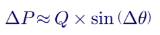
With a 3 MW pickup, a 0.5° combined CT and VT angle error at 300 Mvar consumes almost 90% of the setting. Depending on the error's direction, the element can fail to operate during real motoring or operate falsely when the unit is lightly loaded but still generating.
4.4 Improving accuracy
- Use instrument-quality CTs where possible. IEEE C57.13 metering accuracy classes (0.3 or better) have far lower phase-angle errors than relaying CTs at low currents. Some plants dedicate a metering-class CT core to the 32 function.
- Use relays with phase-angle compensation that can correct known CT and VT angle errors.
- Avoid long CT leads and high burdens that increase phase errors at low current.
- Verify with primary testing at commissioning, including measurement at low power and high reactive output.
- Set below motoring power with margin, typically 50% or less of the minimum motoring power, while staying above the expected measurement error band.
5. Characteristics and logic
5.1 Directional power characteristic
The classic reverse power element operates when the measured power falls below a negative threshold, regardless of reactive power:

Graphically, it is a vertical line in the P-Q plane, to the left of the Q axis. Some relays offer an inclined characteristic or a combined P-Q characteristic to account for low power factor errors.
5.2 Low forward power
A low forward power element (sometimes called 37P or 32L) operates when power falls below a small positive value. It is used in sequential tripping, and for prime movers where reverse power may be difficult to measure, to confirm that the unit has unloaded.
5.3 Time delay
A time delay is essential because reverse power can briefly occur during:
- Synchronizing: if the breaker closes with the generator slightly slow.
- Power swings: during system disturbances, a generator's power oscillates and may briefly reverse.
- Load rejection: governor action can momentarily drive power negative.
Standalone 32 elements on steam turbines commonly use delays of 5 to 30 seconds. Engines often use shorter delays. Sequential tripping logic uses short delays, typically 1 to 3 seconds, because the turbine trip has already been confirmed.
5.4 Two-stage schemes
Many plants use two stages:
| Stage | Purpose | Typical delay |
|---|---|---|
| Stage 1 (sequential trip) | Trips the generator breaker after a turbine trip, supervised by turbine trip contacts or valve position | 1 to 3 s |
| Stage 2 (backup) | Trips for motoring not initiated by a turbine trip, such as governor failure | 10 to 30 s or more |
6. Worked example: setting a 32 element for a 600 MVA steam unit
6.1 Data
| Item | Value |
|---|---|
| Generator | 600 MVA, 22 kV, 0.85 power factor, 2-pole steam turbine-generator |
| GSU transformer | 22/345 kV |
| Motoring power (manufacturer) | 1.5% of rating, 9 MW |
| CT | 20,000:5, relaying class with 0.3° maximum angle error at low current after compensation |
| VT | 22,000:120 V |
| Maximum reactive output while motoring | 300 Mvar |
6.2 Step 1: initial pickup
A pickup of 50% of motoring power gives 4.5 MW. A more sensitive 0.5% (3 MW) is commonly used to provide margin for variations in motoring power.
6.3 Step 2: check measurement error
With a 0.3° angle error at 300 Mvar, the error is about 1.57 MW. The worst-case measured reverse power during actual motoring is then 9 − 1.57 = 7.4 MW, which is above the 3 MW pickup, so the element operates. During light forward generation at, say, +2 MW with full reactive output, the measured value could be 2 − 1.57 = +0.4 MW, which does not reach the −3 MW pickup, so the element does not falsely operate. The setting is secure and dependable.
If the angle error were 0.5°, the error at 300 Mvar would be 2.62 MW. Motoring would still be detected (9 − 2.62 = 6.4 MW above pickup), but the margin is smaller. If the manufacturer's motoring power were only 0.8% (4.8 MW), detection would become unreliable, and compensation or a metering-class CT would be required.
6.4 Step 3: time delays
- Sequential tripping stage: pickup −3 MW, 3 s delay, supervised by turbine trip (stop valve closed) contacts.
- Backup stage: pickup −3 MW, 20 s delay, unsupervised.
6.5 Step 4: secondary values
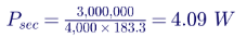
The relay setting is entered as about −4.1 W secondary (three-phase), or in per unit of the relay's nominal rating, depending on the relay.
7. Sequential tripping
7.1 Why sequential tripping exists
If a steam turbine-generator's breaker is opened while the turbine still has steam admitted, the unit loses its electrical load instantly. The turbine accelerates, and if the steam valves do not close fast enough, the unit can overspeed. Large steam units are therefore commonly tripped in sequence:
- Trip the turbine (close stop and control valves).
- Confirm that the turbine is no longer producing power, by detecting reverse power or low forward power.
- Open the generator breaker and field breaker.
This sequence ensures that energy stored in the steam path is absorbed by the grid rather than accelerating the rotor. IEEE C37.102 describes sequential tripping as a recommended practice for steam turbine units for non-electrical trips such as boiler or turbine mechanical trips. For electrical faults inside the generator zone, simultaneous tripping is used because the fault itself must be cleared immediately.
7.2 Failure modes to guard against
| Failure | Consequence | Mitigation |
|---|---|---|
| 32 element fails to operate after turbine trip | Unit motors indefinitely; turbine blade damage | Backup 32 stage, low forward power element, breaker failure initiation |
| Turbine valve fails to close but 32 is supervised by valve contacts | No reverse power; unit stays online producing power | Alarm, operator action and turbine overspeed protection |
| Measurement error prevents pickup | Same as failure to operate | Accuracy review and metering-class CT |
| Generator breaker fails to open | Unit motors | Breaker failure protection initiated by 32 operation |
7.3 Combustion turbine and engine practice
Combustion turbines and engines often use simultaneous tripping for most conditions, because their overspeed risk on load rejection is managed differently and their motoring power is large. Reverse power protection still provides a backup trip if fuel is lost without the breaker opening.
8. Interaction with other generator protection
| Function | Relationship with 32 |
|---|---|
| 40 (loss of field) | Loss of excitation can cause reactive power import and, in some cases, active power swings; 32 settings must not interfere with loss-of-field logic |
| 78 (out of step) | During pole slipping, active power oscillates through positive and negative values; 32 must have enough delay not to trip ahead of the out-of-step scheme |
| 81 (frequency) | Not related directly, but motoring at reduced frequency on islanded systems can mask 32 response |
| 24 (volts per hertz) | Not related directly |
| 50/27 (inadvertent energization) | Protects against breaker closure on a stationary unit; the 32 element is not fast enough for this condition |
| 86 lockout and breaker failure (50BF) | 32 operation should initiate breaker failure for steam units |
NERC PRC-019 requires coordination of generator voltage regulating controls, limiters and protection, and PRC-024 requires generator protection not to trip within specified frequency and voltage ride-through boundaries. Reverse power settings are not usually the subject of these standards, but their time delays must be long enough that power swings during system disturbances do not trip the unit unnecessarily.
9. Reverse power at industrial plants, data centers and microgrids
9.1 Paralleled engine generators
Data centers, hospitals and industrial plants often run several engine generators in parallel on a 480 V, 4.16 kV or 13.8 kV bus during utility outages, and parallel with the utility for testing, peak shaving or closed-transition transfer. If one engine loses fuel or its governor fails, the other generators drive it as a motor. Reverse power protection on each unit removes the failing generator before it overloads the healthy units or suffers engine damage.
9.2 Worked example: 2 MW engine at 480 V
| Item | Value |
|---|---|
| Generator | 2,500 kVA, 480 V, 0.8 power factor, natural gas engine |
| Motoring power (manufacturer) | 12% of kW rating, 240 kW |
| CT | 4,000:5 |
| VT | 480:120 V |
| 32 pickup | 8% of kW rating, 160 kW |
| Time delay | 5 s |
Secondary pickup:
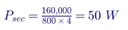
Because engine motoring power is a large fraction of rating, the measurement is easy and accuracy is not a concern. The more important issues are coordination with the paralleling switchgear's load-sharing controls and making sure reverse power does not trip a unit during transient load steps or when another unit's governor responds slowly.
9.3 Export limits at the utility interconnection
A reverse power relay at the point of common coupling (PCC) is often used by US utilities for non-export interconnections, where an on-site generator or battery may serve facility load but must not export to the grid. This is a different application from generator reverse power protection:
| Feature | Generator 32 | PCC reverse power (non-export) |
|---|---|---|
| Location | Generator terminals | Utility service entrance or PCC |
| Direction monitored | Power into the generator | Power from the facility to the utility |
| Purpose | Protect the prime mover | Enforce interconnection agreement, protect utility system |
| Typical delay | Seconds to tens of seconds | Often 2 s or less, per utility requirements |
| Governing documents | IEEE C37.102, manufacturer requirements | IEEE 1547-2018, utility interconnection requirements, state rules |
PCC reverse power settings must account for load variability: if facility load drops suddenly, the generator may export briefly. Minimum import relays (which trip when import falls below a small positive value) are often used instead of pure reverse power relays to give the generator controls time to respond.
10. Inverter-based resources and reverse power
Inverter-based resources do not motor in the same way as synchronous generators. A solar inverter that loses irradiance simply stops producing power, drawing only small auxiliary loads. Battery inverters can intentionally import power to charge. Reverse power protection in its traditional form therefore does not apply to IBRs, but power direction monitoring remains important at:
- PCC non-export or limited-export interconnections for solar and storage behind the meter.
- Hybrid plants where charging from the grid may be restricted by tax credit rules, interconnection agreements or market rules.
- Microgrids where synchronous generators share load with batteries and inverters.
For hybrid plants with synchronous condensers or legacy synchronous generators converted to condensers, reverse power is the intended operating mode, and protection logic must reflect the condensing mode.
11. Synchronous condenser operation
Some hydro and combustion turbine units are designed to operate as synchronous condensers, drawing a small amount of active power from the grid while supplying or absorbing reactive power. Converted retired coal units may also operate as synchronous condensers with the turbine decoupled through a clutch. In these modes:
- Reverse power is normal and the 32 element must be blocked or reset to a different level.
- Mode logic must distinguish condensing operation from accidental motoring.
- Protection settings for loss of field, overexcitation and stator thermal limits change with the operating mode.
12. Testing and commissioning
12.1 Secondary injection
Relay testing verifies pickup, time delay and directional accuracy by injecting currents and voltages at various angles. Tests should include:
- Pickup at the setting angle (180°, pure reverse power).
- Pickup accuracy at very low power factor, with current lagging and leading by close to 90°.
- Time delay at several multiples of pickup.
- Supervision logic for sequential trip stages.
12.2 Primary verification
Primary tests during commissioning confirm the complete measurement chain:
- Compare relay-calculated power with plant metering at several load levels, including minimum load.
- Perform a controlled motoring test, where the manufacturer allows, by closing the turbine valves with the breaker closed and observing the measured reverse power.
- Verify phase rotation, CT polarity and VT connections; a polarity error turns reverse power into forward power in the relay's measurement.
- Confirm sequential trip timing and breaker failure initiation.
12.3 Maintenance
NERC PRC-005 requires maintenance of protective relays, associated communications, voltage and current sensing devices and DC supply for Bulk Electric System generator protection. Reverse power relays on BES generators are part of this program.
13. Common mistakes
- Setting from a rule of thumb instead of the manufacturer's motoring power.
- Ignoring measurement accuracy at low power factor, especially on large steam units.
- Delays too short to ride through synchronizing transients and power swings.
- Delays too long for engines where motoring causes rapid damage.
- Missing breaker failure initiation from the sequential trip stage.
- Wrong polarity or phase rotation in CT or VT wiring.
- Applying generator settings at the PCC, or vice versa, without considering the different purpose.
- Not updating settings when a unit is converted to synchronous condenser operation or its turbine is modified.
14. A reverse power settings checklist
- Obtain the manufacturer's motoring power and allowable motoring time for each prime mover.
- Determine the operating modes, including synchronous condensing.
- Determine CT and VT accuracy classes and phase-angle errors; evaluate measurement error at maximum reactive output.
- Choose pickup below motoring power with margin above measurement error.
- Choose time delays for sequential and backup stages.
- Define supervision logic and breaker failure initiation.
- Coordinate with 40, 78 and other generator protection functions.
- Document secondary settings and test procedures.
- Verify with secondary and primary tests at commissioning.
- Review settings after equipment or operating mode changes.
15. The physics in numbers: rotor angle during motoring
Using the steady-state model with synchronous reactance, consider a round-rotor unit with Xd = 1.80 pu, a GSU reactance of 0.15 pu and a system equivalent of 0.05 pu (total X = 2.00 pu), with internal voltage E = 2.2 pu at full excitation:
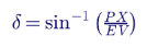
| Operating point | Active power (pu) | Load angle δ |
|---|---|---|
| Full load at 0.85 power factor | +0.85 | +50.6° |
| Zero power (turbine just balancing losses) | 0.00 | 0.0° |
| Motoring at 1.5% of rating | −0.015 | −0.8° |
The machine moves from about +50° to slightly less than zero — a tiny change in angle for a complete reversal of power direction. Nothing about the rotor angle, speed or terminal voltage signals a problem. That is why active power direction, not speed or angle, is the detection quantity, and why a dedicated relay element is needed. Motoring is electrically quiet and mechanically damaging.
16. Where to measure: CT and VT location
Unit-connected generators in US plants normally feed a GSU transformer and one or more unit auxiliary transformers (UATs) tapped from the isolated phase bus between the generator and the GSU. Where the reverse power element measures changes what it sees:
| Measurement location | What the 32 element sees during motoring | Implication |
|---|---|---|
| Generator terminals (or neutral-side CTs) | Only the machine's motoring power | Most direct; sensitive setting needed |
| GSU high-voltage side | Motoring power plus UAT auxiliary load if auxiliaries are still fed from the unit | Larger reverse power and easier detection, but varies with auxiliary load |
| Generator breaker on the low-voltage side (generator circuit breaker) | Motoring power, plus auxiliaries if the UAT is on the GSU side of the breaker | Depends on breaker arrangement |
Neutral-side CTs are often used for generator differential protection; terminal-side CTs are commonly used for directional power. The protection engineer must confirm which CT feeds the 32 element, that its polarity is correct for the chosen power convention and that its accuracy is appropriate.
16.1 Loss of potential
If a VT fuse blows or a VT circuit is opened, the measured voltage on one or more phases collapses, and the calculated three-phase power can be wrong in magnitude or sign. Reverse power elements should be supervised by loss-of-potential (LOP, device 60) logic, which blocks voltage-dependent functions when a VT problem is detected. Without this supervision, a VT fuse failure on a lightly loaded unit can cause a false reverse power trip.
17. Worked example 2: 100 MVA combustion turbine at 13.8 kV
| Item | Value |
|---|---|
| Generator | 100 MVA, 13.8 kV, 0.85 power factor (85 MW) single-shaft combustion turbine |
| GSU transformer | 13.8/138 kV |
| Motoring power (manufacturer) | About 15% of MW rating, 12.8 MW |
| CT | 5,000:5 (ratio 1,000) |
| VT | 13,800:120 V (ratio 115) |
Because motoring power is large, a pickup of half the motoring power — about 7% of MW rating, 6 MW — gives a large margin above measurement error:
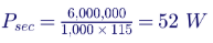
With rated current of 4,184 A and full reactive output of about 60 Mvar, even a 0.5° angle error gives a measurement error of only about 0.5 MW, under 10% of the setting. The time delay is chosen from the manufacturer's allowable motoring duration and plant operating philosophy, typically 5 to 10 seconds.
The contrast with the steam unit is the core lesson: the same protection function needs completely different design attention depending on the prime mover. A combustion turbine 32 setting is easy to make secure; a condensing steam turbine 32 setting requires a measurement accuracy review.
18. Phase-angle compensation in numerical relays
Many numerical generator relays allow the engineer to enter a CT phase-angle correction. If the CT's phase displacement at low current is known from test data or the manufacturer's accuracy curves, the relay rotates the measured current phasor by the correction angle before calculating power:
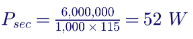
The correction should be based on test data at the current levels seen during motoring, not at rated current, because CT phase errors are typically larger at low current. Overcompensation is as harmful as no compensation, so corrections should be verified during primary testing by comparing relay power with revenue metering at minimum stable load and high reactive output.
19. Motoring duration and turbine damage
Manufacturers often specify how long a unit can safely motor. For condensing steam turbines, allowable times depend on condenser vacuum, exhaust hood cooling sprays and blade design, and may range from several seconds to a few minutes. For units with non-condensing or back-pressure turbines, windage heating can be more severe. Factors that change allowable motoring time include:
- Condenser vacuum: poor vacuum increases windage losses and blade temperature.
- Exhaust hood sprays: spray water cools the last stages and extends allowable time, but can cause erosion if used excessively.
- Unit size: longer last-stage blades experience higher windage heating.
- Steam remaining in the turbine: extraction lines and reheaters can feed steam back into the turbine after a trip.
Reverse power time delays should be well inside the manufacturer's allowable motoring time, with margin for breaker failure clearing if the primary trip path fails.
20. Reading event records
When a generator trips on reverse power, the relay's event report and the plant's digital fault recorder (DFR) or sequence-of-events recorder (SER) show what happened. An engineer reviewing the event should check:
| Record | What it shows |
|---|---|
| Active power trace | Whether power fell gradually after a turbine trip, swung through zero during a system event, or reversed during synchronizing |
| Reactive power trace | Whether high reactive output may have affected measurement accuracy |
| Turbine trip and valve position contacts | Whether the trip was a planned sequential trip or a backup operation |
| Frequency and voltage | Whether a system disturbance caused a power swing |
| Element timing | Pickup time, delay, trip output and breaker opening |
| Breaker status | Whether the breaker opened correctly or breaker failure was needed |
A reverse power trip that occurs during a system disturbance, with frequency and voltage oscillating and no turbine trip, may indicate that the time delay is too short for power swings — a potential NERC misoperation that must be analyzed under PRC-004 for BES units.
21. Redundancy and protection system design
Large generators in US plants typically have two independent protection systems (often called system A and system B), each with its own CTs, VTs, relay and trip path. Reverse power protection is normally included in both, sometimes with different measurement sources. Good practice includes:
- Independent measurement: using different CT cores for the two systems where accuracy allows.
- Diverse logic: a reverse power element in one system and a low forward power element in the other.
- Separate trip paths: each system able to trip the generator breaker and initiate breaker failure.
- Clear alarm philosophy: an alarm stage at a lower delay gives operators warning before the trip stage.
22. Microgrids with mixed sources
Industrial and campus microgrids increasingly combine synchronous engine or turbine generators with battery storage and solar inverters. In these systems:
- Batteries can absorb power from synchronous generators during charging, which looks like load, not reverse power, at the generators — but if the battery controller fails or the load drops sharply, the generators can be pushed toward low forward or reverse power.
- Minimum loading limits on engines often require the microgrid controller to keep each engine above 30% to 40% load to avoid wet stacking and to maintain margin above reverse power.
- Reverse power settings must be coordinated with the microgrid controller's dispatch so normal battery charging does not trip generators.
- Islanding transitions cause transient power swings that the 32 time delay must ride through.
Keentel's microgrid studies model these interactions dynamically, so protection settings and controller logic work together rather than against each other.
23. Standards and documentation
A complete generator protection settings package for reverse power includes:
- Prime mover data sheet with motoring power and allowable motoring time.
- One-line and three-line diagrams showing CT and VT locations, ratios, polarity and accuracy classes.
- Instrument transformer accuracy analysis at motoring conditions.
- Settings calculations for each stage, including secondary values.
- Logic diagrams for sequential tripping, supervision and breaker failure initiation.
- Coordination with other generator protection and plant controls.
- Test procedures for secondary injection and primary verification.
- Settings files and revision history.
This documentation supports NERC PRC-005 maintenance programs, PRC-019 coordination reviews and misoperation analysis under PRC-004 for Bulk Electric System generators.
24. The 32 characteristic on the generator capability diagram
Generator capability curves are drawn in the P-Q plane, with active power on the horizontal axis and reactive power on the vertical axis. Plotting protection characteristics on the same diagram makes their relationships clear:
The reverse power line sits extremely close to the reactive power axis, where most of the generator's operating range during light load and synchronous condensing lies. A small rotation of the measured P-Q point — caused by CT and VT phase errors — moves points across this line. Drawing the measurement error band on the capability diagram is a simple way to show operators and reviewers how much margin the setting has.
25. Synchronizing and reverse power
When a generator is synchronized to the grid, the breaker should close with the machine running very slightly faster than the system, so the unit picks up a small amount of forward power immediately. If the machine is slightly slower, it picks up reverse power at closing. Typical synchronizing limits for large generators, consistent with IEEE C50.12 and C50.13 guidance, include:
| Parameter | Typical limit |
|---|---|
| Phase angle difference at breaker closing | Within about ±10° |
| Voltage difference | Generator voltage 0% to +5% above system voltage |
| Frequency difference (slip) | Generator slightly faster, commonly up to about 0.067 Hz |
Automatic synchronizers and synchronism-check relays (device 25) enforce these limits. A reverse power element with a delay of several seconds rides through any brief reverse power at closing, while a poorly tuned governor that leaves the unit motoring after synchronization is detected by the backup stage. For engine generators at data centers and hospitals, closed-transition transfer schemes synchronize generators to the utility during testing and retransfer, so reverse power delays must accommodate these transitions.
25.1 Inadvertent energization is a different problem
If the generator breaker is closed accidentally while the unit is stationary or on turning gear, the machine starts as an induction motor, drawing very high current and causing severe rotor heating within seconds. Reverse power elements are too slow and too sensitive to protect against this condition. Dedicated inadvertent energization logic (often 50/27, an overcurrent element armed by undervoltage) trips the breaker within a fraction of a second. The two functions complement each other and must both be present on large units.
26. Commissioning test record example
The following is an example of the kind of record Keentel recommends for primary verification of a steam unit reverse power element:
| Test point | Plant metering MW | Plant metering Mvar | Relay-measured MW | Difference | Comment |
|---|---|---|---|---|---|
| Minimum stable load, high Mvar export | +30.0 | +250 | +29.6 | −0.4 MW | Within expected error after compensation |
| Minimum stable load, Mvar absorption | +30.0 | −120 | +30.2 | +0.2 MW | Error changes sign with Q, as expected |
| Turbine trip, motoring | −9.2 | +210 | −8.9 | +0.3 MW | Element picked up; sequential trip in 3.1 s |
| Backup stage test (sequential trip blocked) | −9.1 | +205 | −8.8 | +0.3 MW | Backup trip at 20.2 s |
The record confirms both the accuracy of the measurement at the operating points that matter and the correct operation of each logic path. It becomes the baseline for future maintenance testing.
27. Settings review triggers
Reverse power settings should be reviewed whenever any of the following occurs:
- Turbine or engine modifications: blade replacements, condenser upgrades, engine overhauls or control system replacements.
- CT or VT replacement: new instrument transformers can have different accuracy and phase-angle characteristics.
- Relay replacement or firmware upgrades: measurement algorithms and compensation features differ between relay models.
- New operating modes: synchronous condenser conversion, cycling duty or extended low-load operation.
- Misoperations or near misses: any unexpected reverse power trip, or failure to trip after a turbine trip.
- Changes in auxiliary power arrangements: moving auxiliaries between unit and station service changes what the 32 element measures at some locations.
28. Applying reverse power concepts across the US fleet
The US generation fleet is changing rapidly, and each segment brings its own reverse power considerations:
| Fleet segment | Trend | Reverse power implication |
|---|---|---|
| Coal and older steam units | Cycling duty, low-load operation, retirements and conversions | More time near zero power; greater need for accurate measurement; condensing conversions |
| Combined-cycle plants | Frequent starts and shutdowns, steam turbine operated in bypass during startup | Steam turbine 32 settings must reflect bypass and startup modes; combustion turbines easy to detect |
| Peaking combustion turbines | Frequent fast starts, synchronous condensing at some sites | Mode-dependent logic; clutch status supervision |
| Hydro and pumped storage | Pumping, generating and condensing modes | Pumping mode is intended reverse power; protection must follow mode |
| Reciprocating engine plants | Growth in flexible peaking and data center backup | Short delays and coordination with paralleling controls |
| Nuclear units | Long-term operation, strict design basis | Conservative, well-documented sequential tripping and turbine protection |
Pumped storage deserves special mention: in pumping mode, the motor-generator intentionally draws hundreds of megawatts from the grid. Reverse power protection must be disabled or reconfigured in pumping mode, while other functions, such as phase reversal checks and starting protection, take its place. Mode-switching logic in these plants is among the most complex in generator protection and must be thoroughly tested.
29. Key takeaways
- Motoring is a turbine problem. The generator usually tolerates it; the steam turbine, hydro runner, combustion turbine or engine may not.
- The grid holds the machine at speed. There is no speed or frequency signal to detect motoring; active power direction is the indicator.
- Sensitivity depends on the prime mover. Steam turbines need very sensitive settings; combustion turbines and engines need much less.
- Measurement accuracy matters. At low power factor, small phase-angle errors produce large active power errors.
- Sequential tripping uses reverse power. For steam units, it prevents overspeed by confirming that the turbine has stopped producing power before the breaker opens.
- Time delays must balance damage and security. Short enough to protect the prime mover, long enough to ride through synchronizing and power swings.
- Generator and PCC reverse power are different. One protects the prime mover; the other enforces interconnection agreements.
30. How Keentel Engineering helps
Keentel Engineering provides generator protection, plant electrical and interconnection engineering for utilities, independent power producers, industrial facilities and data centers, from 4 kV to 765 kV.
| Stage | Keentel scope | Outcome |
|---|---|---|
| Protection settings | 32, 40, 78, 87G, 24, 81 and complete generator protection settings per IEEE C37.102 | Coordinated, documented protection |
| Accuracy and CT/VT review | Instrument transformer accuracy analysis at low power factor | Reliable reverse power detection |
| Sequential tripping design | Logic design, supervision and breaker failure integration | Safe unit shutdowns |
| Paralleling and microgrid systems | Engine generator paralleling protection, load sharing and islanding studies | Stable operation during outages |
| Interconnection protection | PCC non-export and minimum import protection per IEEE 1547 and utility requirements | Compliant interconnections |
| Synchronous condenser conversions | Mode logic and protection redesign for converted units | Correct protection for new operating modes |
| Testing and NERC support | Test procedures, commissioning review and PRC-005, PRC-019 and PRC-024 support | Verified, compliant protection |
Why clients choose Keentel Engineering
- Prime-mover-aware protection: settings based on the turbine or engine, not just the generator nameplate.
- Measurement rigor: CT and VT accuracy evaluated, not assumed.
- Plant and grid perspective: protection that coordinates from the generator terminals to the 345 kV switchyard.
- NERC experience: practical support for generator protection maintenance and coordination standards.
- Licensed professional engineering: a Florida-registered firm with offices in Tampa, Austin, Sacramento and Baltimore, supporting projects nationwide.
Need generator protection settings, a sequential tripping review or a paralleling study? Talk to Keentel Engineering at (813) 389-7871, contact@keentelengineering.com, or book a 15-minute scoping call at calendly.com/keentel-engineering/15min.
Part C — Case Studies
The following are illustrative scenarios based on conditions typical of US generating plants and facilities. They show how Keentel Engineering approaches reverse power and generator protection problems; site details are generalised and figures are rounded.
Case Study 1 — 345 kV steam plant: sequential trip that never tripped
Situation. A 650 MVA steam unit connected at 345 kV experiences a turbine trip during a boiler upset. The generator breaker does not open, and operators trip it manually after about two minutes. Turbine inspection finds evidence of last-stage blade heating.
Analysis. Keentel's review finds that the 32 element was set at 0.3% of rating with a single relaying-class CT, and that the unit was exporting high reactive power at the time. Calculated CT angle error at the low current during motoring produced a measurement error larger than the pickup, so the relay saw little or no reverse power. The backup stage relied on the same measurement.
Engineered solution. Keentel recommends a metering-class CT core for the 32 function, enabling the relay's phase-angle compensation, adding a low forward power element supervised by turbine stop valve position, and initiating breaker failure from the sequential trip. Settings are verified by a controlled primary motoring test.
Outcome. The revised scheme detects motoring within seconds of a turbine trip at all reactive power levels tested, and the plant updates its PRC-005 records and test procedures.
Case Study 2 — data center paralleling switchgear: cascading engine trips
Situation. A data center with six 2.5 MW engine generators on a 13.8 kV bus loses utility power. During the outage, one engine loses fuel pressure. Within seconds, two more engines trip on overload, and the facility drops to UPS battery support.
Analysis. Keentel's review shows that the failing engine's 32 element had a 30 s delay copied from a steam turbine setting template. During that time, the failing unit motored at about 12% of rating while the remaining engines picked up its share of load plus its motoring power, overloading them.
Engineered solution. Keentel resets reverse power pickup to 8% of rating with a 3 s delay for each engine, coordinates the settings with the paralleling controls' load-sharing and load-shedding logic, and adds a low fuel pressure trip interlock.
Outcome. In subsequent load bank and outage simulation testing, a failing engine is removed within seconds and the remaining units carry the load without tripping.
Case Study 3 — 138 kV hydro plant: condensing mode and false trips
Situation. A hydro plant at 138 kV begins operating two units as synchronous condensers to support voltage in a growing solar region. The units repeatedly trip on reverse power when switched to condensing mode.
Analysis. Keentel finds that the 32 elements were not blocked during condensing mode, and the motoring power with water depressed was only about 0.5% of rating, close to the original pickup. Mode transitions also caused brief power swings.
Engineered solution. Keentel designs mode-dependent protection: the 32 element is blocked in confirmed condensing mode (supervised by wicket gate and air depression status) and remains active in generating mode. A separate reverse power stage with higher pickup detects abnormal power draw in condensing mode. Loss-of-field and overexcitation settings are reviewed for the new operating range.
Outcome. The units operate in condensing mode without nuisance trips, while retaining protection for unintended motoring in generating mode.
Part D — Technical FAQ: Reverse Power Protection
Reverse power is active power flowing from the grid into a generator. It occurs when the prime mover supplies less mechanical power than the machine's losses, so the generator operates as a synchronous motor.
The interconnected grid holds the machine at synchronous speed. The rotor angle shifts so that the machine draws enough power to make up its losses and drive the prime mover.
Usually not. The synchronous machine can motor without damage. The risk is to the prime mover: steam turbine blades, hydro runners, combustion turbine gearboxes or reciprocating engines.
Device 32 is a directional power relay. In generator protection it is set to detect power flowing into the machine and trip or alarm after a time delay.
Condensing steam turbines need very little power to motor, often under 1% to 3% of rating, so the reverse power element must detect very small power flows.
During motoring, active power is tiny compared with apparent power. Small phase-angle errors in instrument transformers create active power errors proportional to reactive power, which can mask or mimic reverse power.
Divide the primary power setting by the product of the CT ratio and VT ratio. Relay manuals specify whether settings are three-phase or per-phase.
Reverse power can occur briefly during synchronizing, power swings and load rejection. The delay prevents unnecessary trips while still protecting the prime mover.
A shutdown sequence for steam units in which the turbine is tripped first, and the generator breaker opens only after reverse or low forward power confirms that the turbine is no longer producing power. It prevents overspeed.
For electrical faults in the generator zone, such as stator faults, the unit is tripped immediately. Sequential tripping is used for non-electrical trips where a short delay is safe.
An element that operates when active power falls below a small positive value. It confirms that a unit has unloaded and is often used with sequential tripping.
Typically 5% to 25% of rating, depending on engine size and design. Reverse power settings for engines are therefore easier to measure but must coordinate with paralleling controls.
Unburned fuel can accumulate in the exhaust and intake, creating fire or explosion risk, and mechanical components can be stressed.
With water present, motoring can cause cavitation and rough operation. With water depressed for condensing operation, motoring power is very small and the unit may be operating intentionally as a synchronous condenser.
NERC does not specify reverse power settings, but PRC-005 requires maintenance of generator protection systems on BES units, and PRC-019 and PRC-024 require coordination of generator protection and ride-through behavior.
Generator reverse power protects the prime mover. PCC reverse power or minimum import protection enforces non-export interconnection requirements under IEEE 1547 and utility rules.
Not in the traditional sense, because inverters do not motor. Power direction monitoring is still used at the PCC for non-export interconnections and for hybrid plant charging rules.
During pole slipping, active power oscillates through positive and negative values. The 32 time delay must allow the out-of-step scheme to operate appropriately.
By secondary injection at the pickup angle and at low power factors, and by primary verification comparing relay measurements with plant metering, including a controlled motoring test where permitted.
Using a generic setting instead of the manufacturer's motoring power and ignoring measurement accuracy at low power factor.
References and Further Reading
Links were current at publication (October 2026).
- IEEE Std C37.102, Guide for AC Generator Protection. IEEE.
- IEEE Std C37.2, Standard for Electrical Power System Device Function Numbers, Acronyms, and Contact Designations. IEEE.
- IEEE Std C57.13, Standard Requirements for Instrument Transformers. IEEE.
- IEEE Std 1547-2018, Standard for Interconnection and Interoperability of Distributed Energy Resources with Associated Electric Power Systems Interfaces. IEEE.
- IEEE Std C37.101, Guide for Generator Ground Protection; IEEE Std C37.106, Guide for Abnormal Frequency Protection for Power Generating Plants. IEEE.
- NERC Reliability Standards PRC-005, PRC-019 and PRC-024. North American Electric Reliability Corporation.
- NFPA 110, Standard for Emergency and Standby Power Systems; NFPA 70, National Electrical Code, Article 705. National Fire Protection Association.
- J. L. Blackburn and T. J. Domin, Protective Relaying: Principles and Applications. CRC Press.
Disclaimer
This article is general technical information for educational purposes. It is not engineering advice for any specific project and does not create a professional relationship. Motoring powers, settings, accuracy values and time delays are illustrative; actual protection settings must follow the prime mover and generator manufacturers' requirements, relay manufacturer instructions, applicable standards and project-specific engineering analysis, sealed by a licensed professional engineer where required.
Case studies are illustrative scenarios based on typical project conditions, not records of specific client projects. Figures are rounded and indicative.
IEEE, NERC, NFPA, ANSI and other names are the property of their respective owners. Keentel Engineering is not affiliated with or endorsed by these organisations or any relay or equipment manufacturer.
| Office | Address | Phone |
|---|---|---|
| Head Office — Tampa | 400 N Ashley Dr STE #2600, Tampa FL 33602 | (813) 389-7871 |
| Austin | 5900 Balcones Drive STE 100, Austin TX 78731 | (512) 591-0752 |
| Sacramento | 1401 21st St Ste R, Sacramento CA 95811 | (916) 913-4524 |
| Baltimore | 306 W Redwood St STE 200, Baltimore MD 21201 | (410) 225-2181 |

About the Author:
Sandip "Sonny" R. Patel, P.E.
IEEE Senior Member · Founder & CEO, Keentel Engineering
In 1995, Sonny Patel earned his Electrical Engineering degree from the University of Illinois. But degrees don't build legacies — action does.
For three decades, he has worked the power industry from every side of the table: 16 years as a utility engineer at Exelon/Commonwealth Edison; generation leadership across hydroelectric, industrial steam turbine, and a 9 GW renewable fleet; NERC Regional Entity Senior Compliance Engineer and Audit Team Lead, auditing some of the nation's largest utilities; and testing and commissioning lead on equipment up to 765 kV — the very top of the North American grid.Utility. Generator. Regulator. Consultant. Few engineers have seen all four seats. Fewer still have sat in them.
His experience spans nuclear, hydro, conventional generation, renewables, oil and gas, mining — and today's data centers, where he is authoring a three-book series on data center design. He is a Licensed Professional Engineer in six states and a Licensed Electrical Contractor in Florida (Unlimited EC) — he doesn't just design the work; he's qualified to stand behind its execution.Today, as Founder and CEO of Keentel Engineering, Sonny leads a nationwide team of engineers delivering substation design, power system studies, NERC compliance, and commissioning — done right, coast to coast.Three decades. Every side of the table. One standard: accountable engineering.
Services

Let's Discuss Your Project
Let's book a call to discuss your electrical engineering project that we can help you with.
About the Author:
Sandip "Sonny" R. Patel, P.E.
IEEE Senior Member · Founder & CEO, Keentel Engineering
In 1995, Sonny Patel earned his Electrical Engineering degree from the University of Illinois. But degrees don't build legacies — action does.
For three decades, he has worked the power industry from every side of the table: 16 years as a utility engineer at Exelon/Commonwealth Edison; generation leadership across hydroelectric, industrial steam turbine, and a 9 GW renewable fleet; NERC Regional Entity Senior Compliance Engineer and Audit Team Lead, auditing some of the nation's largest utilities; and testing and commissioning lead on equipment up to 765 kV — the very top of the North American grid.
Utility. Generator. Regulator. Consultant. Few engineers have seen all four seats. Fewer still have sat in them.
His experience spans nuclear, hydro, conventional generation, renewables, oil and gas, mining — and today's data centers, where he is authoring a three-book series on data center design. He is a Licensed Professional Engineer in six states and a Licensed Electrical Contractor in Florida (Unlimited EC) — he doesn't just design the work; he's qualified to stand behind its execution.
Today, as Founder and CEO of Keentel Engineering, Sonny leads a nationwide team of engineers delivering substation design, power system studies, NERC compliance, and commissioning — done right, coast to coast.Three decades. Every side of the table. One standard: accountable engineering.
Leave a Comment
Thank you for contacting us.
We will get back to you as soon as possible.
We will get back to you as soon as possible.
Oops, there was an error sending your message.
Please try again later.
Please try again later.
Related Posts
By Team 2 Dexora
•
October 20, 2026
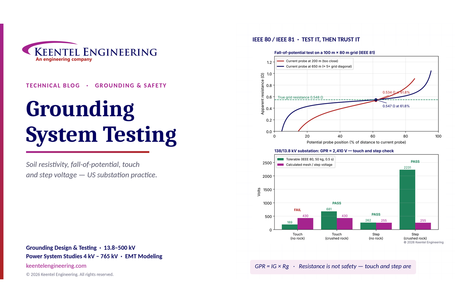
Explore grounding system testing with Keentel Engineering. Learn IEEE 80/81 methods, soil resistivity, ground resistance, and touch and step voltage safety.
By SANDIP R PATEL
•
October 13, 2026
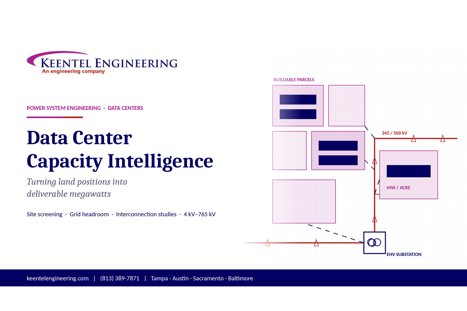
Plan data center capacity with land screening, MW-per-acre estimates, grid power availability and interconnection feasibility studies from Keentel Engineering.
By SANDIP R PATEL
•
October 11, 2026
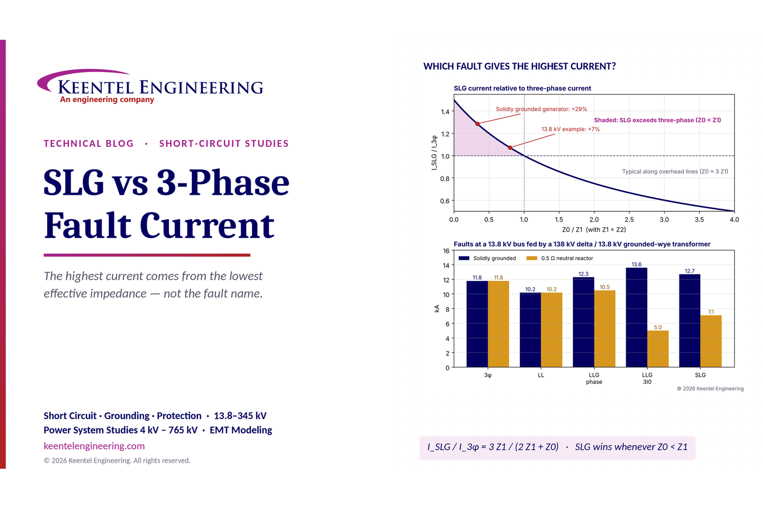
Learn which fault produces the highest current at a bus, why SLG faults can exceed three-phase faults, and how symmetrical components determine fault duty.
By SANDIP R PATEL
•
October 11, 2026
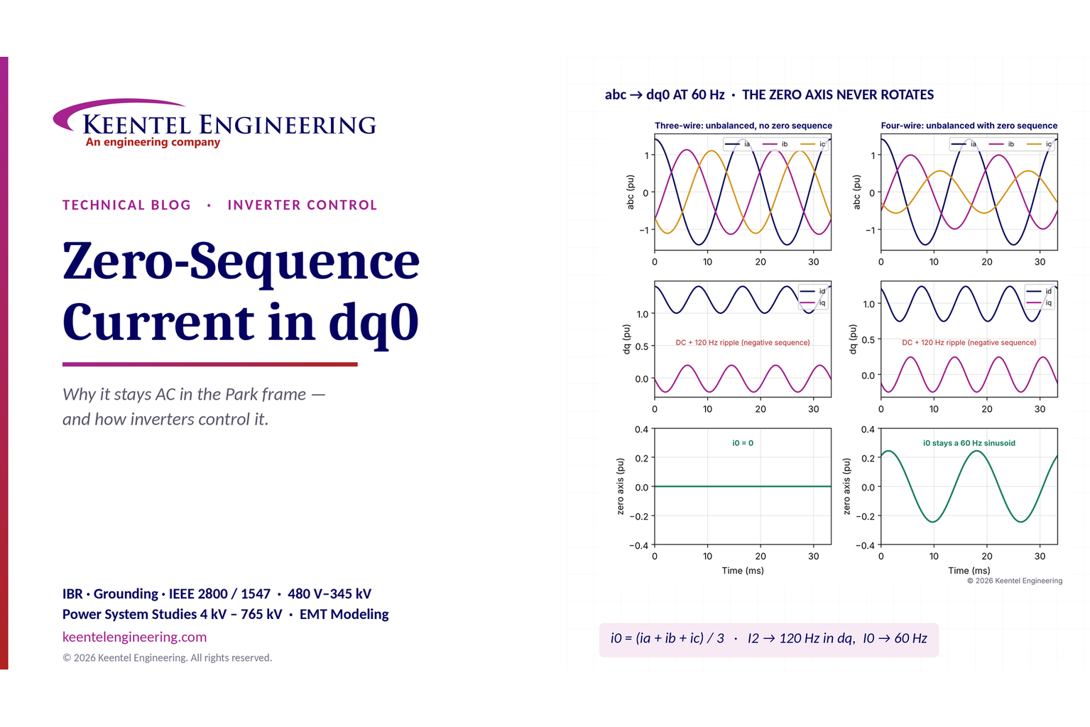
Learn why zero-sequence current pulsates in the dq0 frame, how Park's transformation works, and how inverter controls handle unbalance and ground faults.
By SANDIP R PATEL
•
October 11, 2026
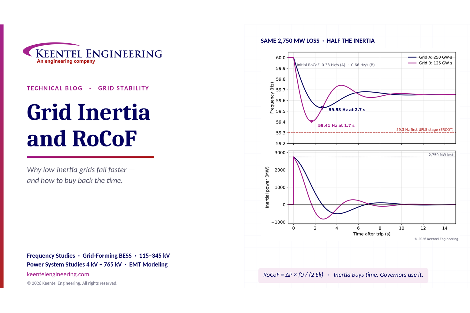
Explore grid inertia, RoCoF and frequency response, with swing equation calculations, frequency nadir analysis and US power system simulation examples.
By SANDIP R PATEL
•
October 11, 2026
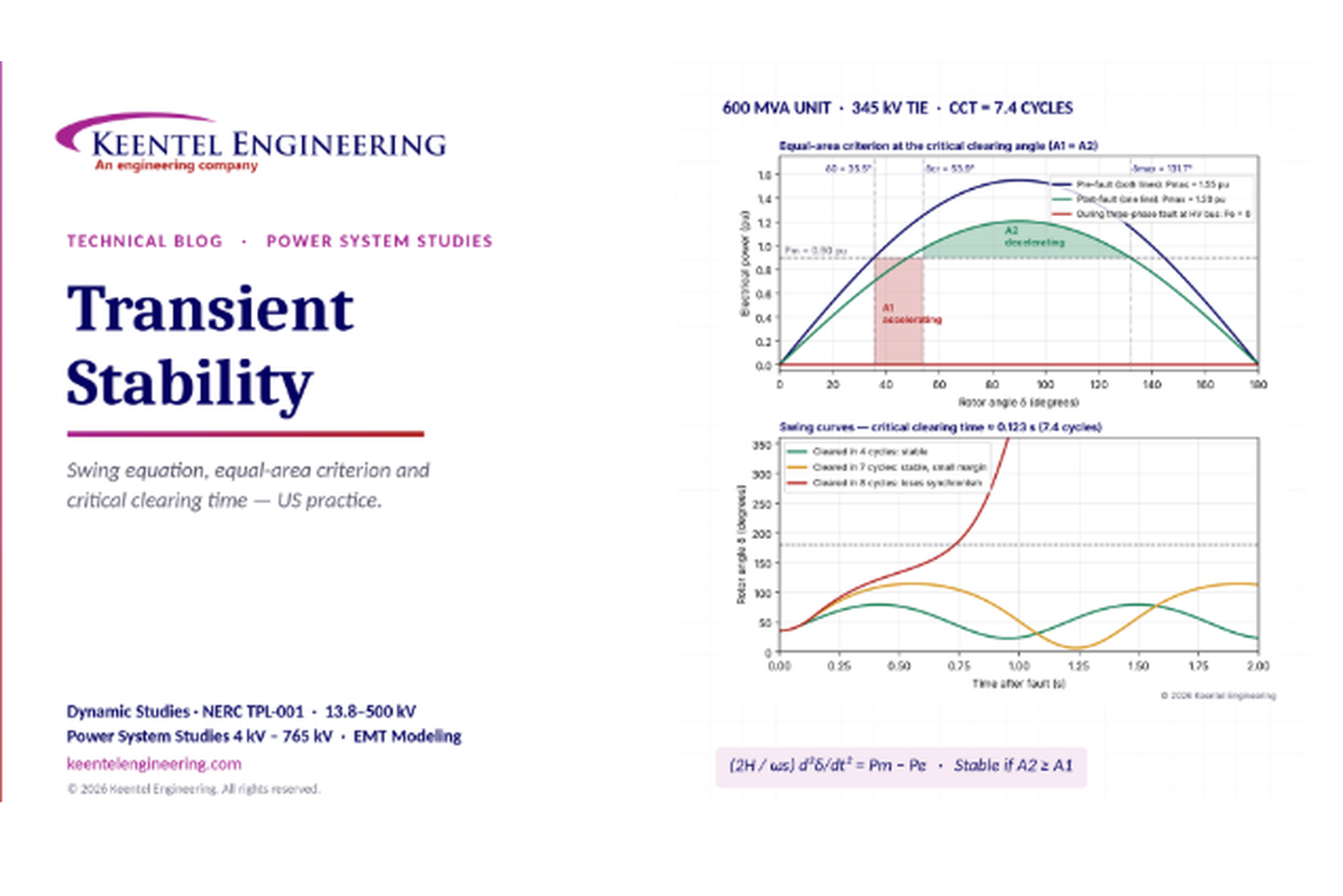
Learn transient stability analysis, swing equation, equal-area criterion and critical clearing time with a 345 kV worked example and NERC TPL-001 guidance.
By SANDIP R PATEL
•
October 11, 2026
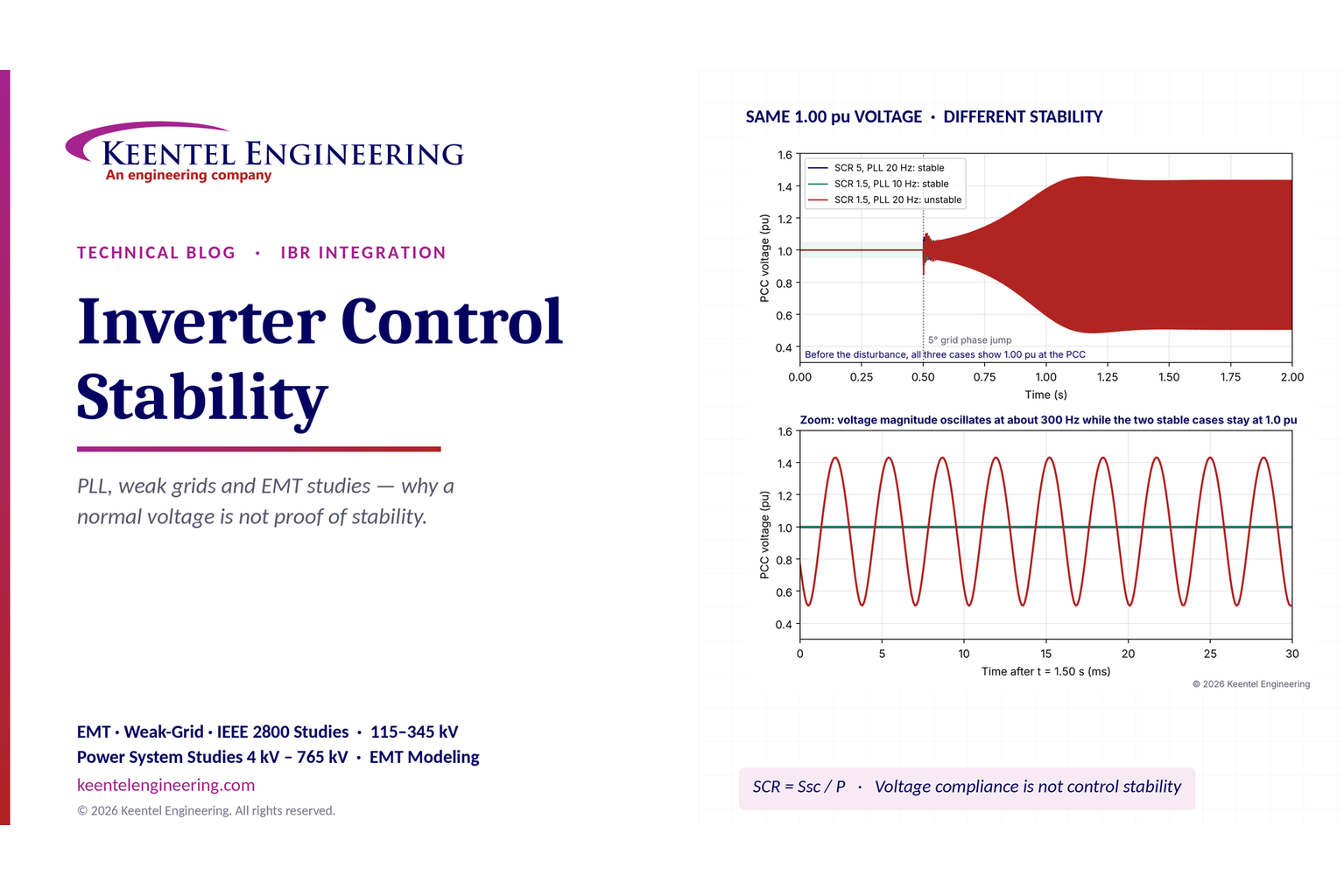
Learn why inverter controls become unstable in weak grids, how PLL bandwidth and SCR affect stability, and how PSCAD EMT studies identify and mitigate oscillations.
By SANDIP R PATEL
•
October 11, 2026
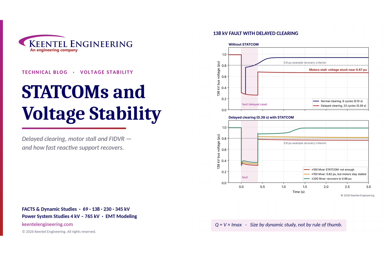
Learn how STATCOMs improve voltage stability and prevent FIDVR. Explore reactive power sizing, delayed fault clearing, NERC criteria and 138 kV simulation results.
By SANDIP R PATEL
•
October 10, 2026
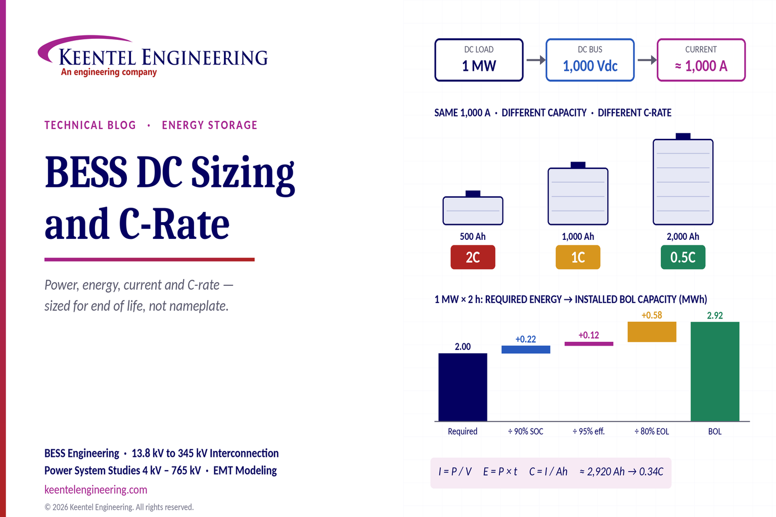
Learn BESS DC sizing with power, energy, current and C-rate calculations, battery losses, degradation and a 100 MW/400 MWh utility-scale example.