A Coordinated Electric System Interconnection Review—the utility’s deep-dive on technical and cost impacts of your project.
Challenge: Frequent false tripping using conventional electromechanical relays
Solution: SEL-487E integration with multi-terminal differential protection and dynamic inrush restraint
Result: 90% reduction in false trips, saving over $250,000 in downtime
| Category | Metric |
|---|---|
| VPP capacity (Lunar Energy) | 650 MW |
| Lunar funding raised | US$232 million |
| Data center BESS example | 31 MW / 62 MWh |
| ERCOT grid-scale batteries | 15+ GW |
| LDES tenders (H1 2026) | Up to 9.3 GW |
| Lithium-ion share of LDES by 2030 | 77% |
| FEOC initial threshold | 55% |
| BESS tariff rate (2026) | ~55% |
| Capacity gain from analytics | 5–15% |
What is T&D Co-Simulation?
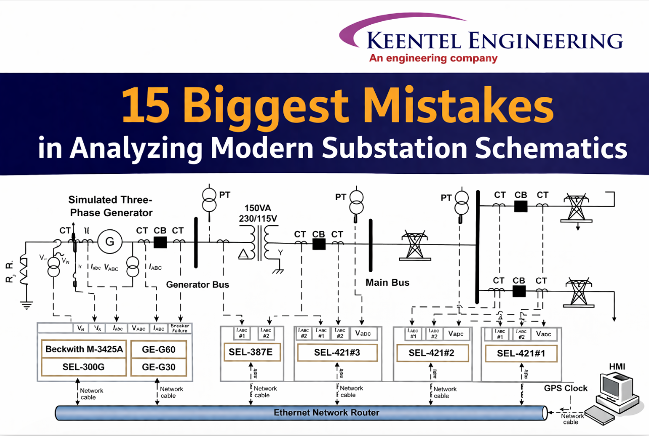
The 15 Biggest Mistakes in Analyzing Modern Substation Schematics
Apr 11, 2026 | blog
As the grid transitions from copper-and-relay to fiber-and-software, schematic analysis demands a fundamentally new approach. Here's what engineers and their clients get wrong, and how Keentel Engineering ensures your protection systems never let you down.
By Keentel Engineering Team
Based on current field experience
15 min read
Digital SubstationsIEC 61850Protection EngineeringGOOSEHV SchematicsGrid Reliability
A single misinterpreted line, an overlooked logical node, or a misunderstood protection zone can lead to catastrophic equipment failure, grid instability, or severe safety hazards. This is what modern substation schematic analysis really looks like and where even experienced engineers make critical mistakes.
Mistake 01
Misinterpreting Protection Zones and Overlapping
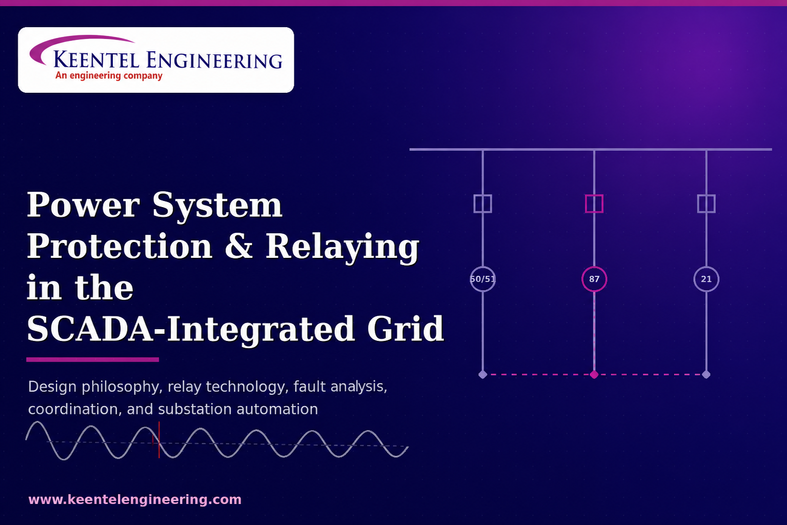
One of the most foundational errors in schematic analysis is failing to accurately define and overlap protection zones. Protection zones are physically defined by the placement of Current Transformers (CTs) not by assumption. Analyzing a Single-Line Diagram (SLD) without verifying the physical CT placement relative to circuit breakers is a critical shortcut that creates potentially lethal blind spots.
If protection zones don't overlap correctly, a fault occurring between the circuit breaker and the CT may be seen as "out of zone" by primary protection, while bus protection ignores it entirely based on CT configuration. The result: a completely unprotected zone.
Every piece of primary equipment must be covered by at least two independent overlapping protection zones. Any gap even a small one can allow a fault to go uncleared, causing catastrophic substation failure and potential grid instability.
Keentel Engineering Approach
Our protection engineers perform systematic zone mapping for every substation project, cross-referencing SLD diagrams with physical CT placement and breaker positions to eliminate blind spots before commissioning.
Mistake 02
Confusing Physical Connections with Logical Nodes in IEC 61850
In digital substations using the IEC 61850 standard, the paradigm shifts entirely. Engineers trained on conventional substations instinctively look for hardwired trip signals. In a digital environment, the physical drawing may only show an Ethernet connection between an IED and a switch — but the actual "wiring" exists in the logical realm through GOOSE (Generic Object Oriented Substation Event) messages.
Failing to cross-reference the physical Ethernet topology with logical node mapping such as PTRC (protection trip conditioning) and XCBR (circuit breaker modeling) leads to a complete misunderstanding of how a trip signal propagates from protection relay to breaker.
Think of it this way: analyzing the physical Ethernet layout without the logical mapping is like looking at a highway and trying to guess which car is carrying a specific letter. The infrastructure is visible, but the intent is hidden in the data packets.
A GOOSE message published by one protection IED may be subscribed to by five different breaker IEDs. Physically, they all connect to the same switch but logically, they are separate point-to-point or point-to-multipoint virtual wires. Both the physical SCD layout and the GOOSE/SV logical flows must be analyzed together.
Mistake 03
Ignoring the Nuances of the Substation Configuration Language (SCL)
Directly tied to the previous point, engineers often analyze drawn schematics without validating them against the Substation Configuration Language (SCL) files. The paper schematic is frequently just a high-level overview; the true operational schematic is the System Configuration Description (SCD) file.
When engineers fail to verify that Dataset configurations, Report Control Blocks (RCBs), and GOOSE control blocks in the SCD file match the intended logic on engineering drawings, dangerous divergences go undetected. If an IED's capability description (ICD) is updated without reflecting those changes in the SCD file, the physical schematic becomes dangerously obsolete.
There are four common failure modes here: the "invisible wiring" problem (you can't trace a misconfigured GOOSE message on paper), siloed teams using non-integrated tools, the sheer scale of data models leading to "default acceptance," and late-stage commissioning pressure driving undocumented patches.
Keentel Engineering Approach
We maintain synchronized documentation between physical drawings and SCL/SCD files throughout the project lifecycle including post-commissioning updates. Our integrated
P&C and automation teams eliminate the siloed handoffs that create dangerous discrepancies.
Mistake 04
Overlooking DC Control Circuit Transients and Voltage Drops
While much attention is given to AC primary systems, the DC control circuits are the lifeblood of the substation. A frequent analytical mistake is assuming a perfect DC source. Engineers must account for the transient voltage drop when multiple trip coils are energized simultaneously — for example, during a breaker failure scenario.
If wire sizing or battery bank capacity shown in the schematic is insufficient, the voltage at the breaker trip coil may drop below its minimum operating threshold. A trip coil is a large inductor — the DC control circuit is fundamentally a series RL circuit. The current doesn't instantaneously reach steady state; it rises exponentially according to the circuit's time constant (τ = L/R).
Analyzing the schematic without calculating the equivalent circuit — accounting for lead resistance and coil inrush current can result in breakers physically failing to trip when called upon during a real fault event.
In digital substation architecture, the physical DC trip circuit is localized to the switchyard kiosk and breaker mechanism, typically using 110V or 125V DC from the local yard distribution board. While shorter cable runs in digital substations reduce some voltage drop concerns, the RL transient behavior of the trip coil remains a critical analysis requirement.
Mistake 05
Misunderstanding Grounding and Bonding Paths
Substation grounding schematics are frequently treated as secondary to protection and control drawings. This is a mistake that carries severe safety consequences. Correct analysis requires visualizing the flow of zero-sequence currents (3I₀) during a ground fault and ensuring the drawn grid meets IEEE 80 standards for the specific soil resistivity of the site.
One particularly dangerous configuration is daisy-chained grounding, where Equipment A grounds to Equipment B, which grounds to Equipment C, which finally ties to the main grid. If a single lug corrodes or a copper connection is disrupted, Equipment A becomes completely ungrounded. Even with intact connections, cumulative series impedance causes massive voltage drops across the bonding path during lightning strikes, elevating equipment casing potential to dangerous levels.
Every metallic structure, transformer neutral, and surge arrester must have a direct, independent connection to the main ground grid never through a daisy chain. Ground Potential Rise (GPR) during asymmetrical faults can reach lethal levels without proper design.
Mistake 06
Failure to Correlate Three-Line Diagrams with Single-Line Diagrams
The SLD provides functional overview; the Three-Line Diagram reveals precise phase connections. Analyzing the SLD in isolation and assuming standard A-B-C phase rotation across all equipment is a common and costly trap. Errors are especially prevalent at transition points — where transmission lines enter the substation or around power transformers with specific vector groups such as YNd11.
Missing phase transpositions or incorrect connections to directional relays can lead to catastrophic maloperation of distance or differential protection schemes. The protection relay may see a forward fault as reverse, or calculate massive differential current during normal load flow — both leading to either failure to trip or false tripping.
Keentel Engineering Approach
Keentel Engineering's review process always cross-references SLD with Three-Line diagrams, especially at transformer interfaces, to verify phase rotation and polarity alignment for all differential and directional protection schemes.
Mistake 07
Incorrect Integration of Generator Circuit Breakers (GCB)
When a substation interfaces directly with power generation, schematics for Medium Voltage (MV) generator circuit breakers require specialized scrutiny. Analyzing GCBs using standard transmission breaker criteria is a significant mistake. GCBs must handle unique phenomena, particularly highly asymmetric short-circuit currents and severe Transient Recovery Voltages (TRV).
When reviewing the schematic, engineers must check sizing, the placement of surge capacitors, and the location of the GCB relative to the step-up transformer. Crucially, generator faults exhibit delayed current zero-crossings, meaning the current waveform does not cross zero at the expected moment during a fault.
Failing to account for delayed current zero-crossings when analyzing trip logic can result in the GCB attempting to interrupt current before a zero-crossing occurs potentially destroying the breaker upon opening.
Mistake 08
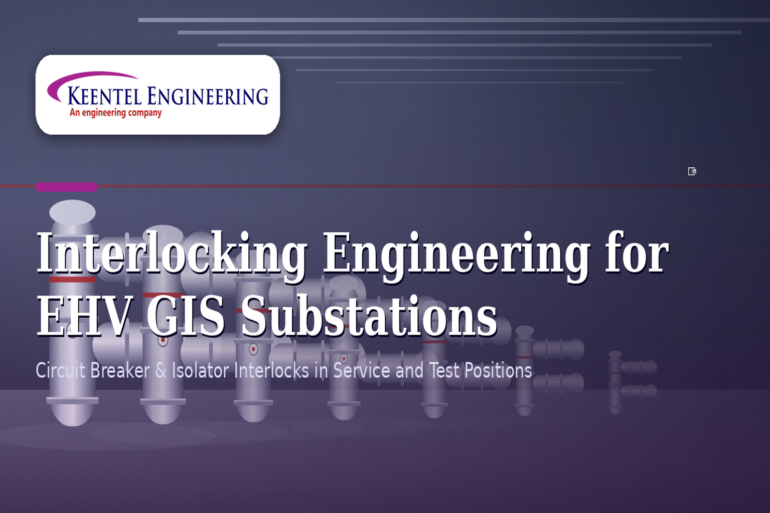
Neglecting Interlocking Logic in Hybrid Switchgear
Interlocking schemes prevent operators from making fatal errors such as opening a disconnector under load or closing an earth switch onto a live bus. In modern and hybrid switchgear, failing to verify the complete interlocking loop across both hardware and software layers is a dangerous oversight.
Engineers often check the hardwired auxiliary contacts in the schematic but overlook the software-based interlocks programmed into the bay controller. A comprehensive analysis must trace the logic from the physical status of the breaker (52a/52b contacts), through disconnector motor drive circuits, and into the IED logic equations verifying no operational blind spots exist in either layer.
Mistake 09
Misjudging CT/VT Polarities and Burden Constraints
Instrument transformers are the eyes of the protection system. Misinterpreting polarity marks on a schematic is a classic, frequently repeated mistake. For differential and directional protection, reversed polarity will cause the relay to see a forward fault as reverse — or calculate a massive differential current during normal load flow, causing false operation.
A second failure is not calculating the secondary burden. Simply looking at the wiring diagram isn't enough — engineers must calculate the total burden (Z = R_burden + R_lead + R_relay internal) and ensure it does not exceed the CT's rated capacity. Overburdened CTs will saturate during a fault, distorting the secondary waveform and effectively blinding the protection relay at the exact moment it is needed most.
Keentel Engineering Approach
Every CT/VT circuit in our designs includes explicit burden calculations and polarity verification, documented in our relay coordination studies and reviewed independently before commissioning.
Mistake 10
Underestimating Cyber-Physical Attack Vectors in Schematic Topology
With digital substations, the schematic now includes IT infrastructure managed Ethernet switches, routers, and firewalls. Viewing these components strictly as data pathways, rather than potential cyber-physical attack vectors, is a modern and increasingly consequential mistake.
Essential protection and control signals breaker trip commands (GOOSE messages) and digitized measurements (Sampled Values) travel over local Ethernet networks. This connects previously isolated physical switchgear directly to the substation's cyber infrastructure. Failing to verify isolation between the station bus (MMS/IEC 61850-8-1) and the process bus (Sampled Values/IEC 61850-9-2) is a critical design gap.
The schematic must explicitly show logical and physical segregation, VLAN configurations, and boundary protection devices. Ignoring this transforms a robust power system into a vulnerable network target one where a compromised HMI or engineering workstation can issue malicious breaker commands.
Mistake 11
Poor Translation of Legacy Schematics to Modern IED Logic
Upgrading brownfield substations means migrating from legacy electromechanical or static relays to modern microprocessor-based IEDs. The massive pitfall here is attempting a one-to-one translation of old schematic logic to new IED programming.
Legacy schematics often rely on the inherent physical properties of old relays contact bounce, slow operating times, high burden which naturally filtered out transients and noise. Modern IEDs operate in milliseconds and respond to everything. Copying old wiring logic into IED programming without adding appropriate debounce timers or transient blocking logic will result in the new system being plagued by nuisance tripping.
Mistake 12
Disregarding Merging Unit (MU) Synchronization in Process Bus Architecture
In a true digital substation, traditional copper wires from CTs and VTs are replaced by Merging Units (MUs) in the switchyard. These MUs digitize analog signals into Sampled Values (SV) and stream them over fiber optics. A critical oversight when reviewing process bus schematics is ignoring the time synchronization architecture.
Without hyper-accurate synchronization typically via Precision Time Protocol (PTP, IEEE 1588) — the Sampled Values from different MUs will be misaligned in time. If the schematic does not clearly detail the grandmaster clock hierarchy, network topology, and PTP profiles used, the differential protection algorithms will calculate false operating currents and trip the substation under normal conditions.
Mistake 13
Inadequate Review of Breaker Failure (BF) Scheme Routing
Breaker Failure (ANSI 50BF) protection is the ultimate safety net. If a primary breaker fails to clear a fault, the BF scheme must trip all adjacent breakers to isolate the fault. The mistake lies in not rigorously tracing the routing of these critical trip signals across the entire substation schematic.
Engineers sometimes assume the BF signal only needs to reach the bus protection relay this is wrong. The schematic must verify that the BF initiate signal (BFI) is triggered by the primary protection trip, that current detectors are properly configured, and that retrip and cross-trip commands are routed correctly — often requiring interaction between multiple IEDs and potentially remote substations via teleprotection channels.
Mistake 14
Overlooking Arc Flash Mitigation Control Loops
Modern switchgear schematics often incorporate active arc flash mitigation systems, using optical light sensors combined with overcurrent elements to detect an arc and trip the system in milliseconds. The mistake is treating the arc flash schematic independently from the primary protection schematic.
If logic loops are not carefully reviewed together, an arc flash sensor could be triggered by a camera flash or ambient light during maintenance. The schematic must clearly show the AND logic gating — requiring both a flash of light and a sudden spike in current — before an ultra-fast trip command is issued to the upstream breaker. Missing this coordination means either unwanted trips during maintenance or, worse, a failed arc flash response during a real event.
Mistake 15
Failing to Update As-Built Drawings After Asset Management Interventions
Perhaps the most pervasive mistake of all is not a failure to understand the schematic — it's a failure to analyze the correct schematic. Substations are living entities undergoing continuous maintenance, asset replacement, and firmware upgrades. When field modifications are not fed back into the engineering database to produce accurate as-built schematics, subsequent analysis is based on fiction.
Replacing a failing SF6 breaker with a vacuum breaker, updating IED firmware, or making emergency patches during commissioning if none of these are back-annotated into official design drawings, the documentation permanently falls out of sync with reality. Relying on outdated schematics during a fault investigation or planned expansion inevitably leads to design flaws and dangerous operational errors.
Keentel Engineering Approach
Keentel Engineering maintains rigorous as-built documentation protocols with formal change control procedures. Every field modification is tracked, reviewed, and reflected in the official schematic package before project closeout.
The Core Shift: From Copper to Code
The most profound mistake engineers make when analyzing modern digital substation schematics is attempting to read them exclusively through the lens of legacy copper wiring. The transition from physical terminal blocks to virtual data streams is not merely a hardware upgrade — it is a fundamental paradigm shift demanding a new analytical approach. Mastering modern digital substations means expanding foundational protection expertise (distance, differential, overcurrent concepts remain the same) to achieve genuine fluency in network architecture and digital configuration languages. The engineers who succeed are those who view the network switch and the SCL file with the same reverence they once held for the multimeter and the test block.
Frequently Asked Questions (FAQs)
What exactly is IEC 61850 and why does it change how we analyze substation schematics?▾
IEC 61850 is the international standard for communication networks and systems for power utility automation. It fundamentally changes substation engineering by replacing hardwired copper connections between devices with high-speed digital communication over Ethernet networks.
In a conventional substation, every protection and control signal had a dedicated copper wire — if you saw a wire on the drawing, you could physically trace it. In an IEC 61850 digital substation, the same physical Ethernet fiber cable carries hundreds of different signals simultaneously.
The actual "wiring" is defined in software through:
- GOOSE messages (Generic Object Oriented Substation Event) — used for high-speed protection and control commands, such as trip signals between IEDs
- Sampled Values (SV) — used by Merging Units to stream digitized current and voltage measurements over the network
- MMS (Manufacturing Message Specification) — used for supervisory SCADA communication between the station level and bay level
This means a schematic analysis that stops at the physical layer is incomplete. Engineers must also read and validate the SCD file (System Configuration Description), which defines all the logical connections, datasets, and control blocks that actually govern system behavior.
What is the difference between the physical view and logical view of a digital substation?▾
This is one of the most important conceptual distinctions in modern substation engineering.
The Physical View shows what you can see and touch in the substation yard and control building: fiber optic cables, Ethernet switches, IEDs (Intelligent Electronic Devices), Merging Units, and process interface units. A physical drawing shows these components connected to an Ethernet switch — but tells you nothing about which signals travel between them or what those signals mean.
The Logical View shows the functional behavior: which GOOSE message from which IED triggers a trip command in which breaker controller, how Sampled Values flow from Merging Units to protection relays, and how the bay controller interlocks communicate with each other. This view only exists in the SCL/SCD configuration files and related documentation.
A thorough schematic analysis must cover both views simultaneously. Keentel Engineering produces integrated documentation that links physical one-line drawings with their corresponding logical communication diagrams, so that both commissioning engineers and future maintenance technicians can trace the full signal path.
What is a GOOSE message and why is it critical for protection scheme analysis?▾
GOOSE (Generic Object Oriented Substation Event) is a high-speed, peer-to-peer multicast messaging protocol defined in IEC 61850. It is the digital replacement for hardwired binary signals between protection and control devices in a substation.
GOOSE messages are critical because they carry time-sensitive protection commands — including breaker trip signals, intertripping between substations, interlocking states, and breaker failure initiates. They are designed to retransmit rapidly and at increasing intervals, so that any receiving IED that misses a message quickly receives another.
When analyzing a protection scheme, engineers must verify:
- Which IEDs publish each GOOSE dataset (the source)
- Which IEDs subscribe to each GOOSE message (the destinations)
- The VLAN and AppID configuration (to ensure proper network segmentation)
- The dataset contents (that the correct logical nodes and data attributes are included)Transmission timing and retransmission rates
- What happens if a GOOSE message is lost or delayed — does the receiving IED fail safe?
A misconfigured GOOSE subscription means a breaker simply won't receive a trip command during a fault — yet nothing in the hardware wiring will look wrong.
What is a Merging Unit and what synchronization issues should engineers watch for?▾
A Merging Unit (MU) is the field device in a process bus architecture that replaces the traditional hardwired secondary connections from Current Transformers (CTs) and Voltage Transformers (VTs). It samples the analog CT and VT outputs at a very high rate (typically 80 or 256 samples per power frequency cycle) and transmits these digitized measurements as Sampled Values (SV) streams over the process bus Ethernet network to protection IEDs and meters.
The critical synchronization issue is that differential protection algorithms compare current phasors from multiple locations simultaneously — for example, currents at both ends of a transformer or busbar. If the Sampled Values from different Merging Units are even slightly misaligned in time, the protection relay will calculate a false differential current and may trip the substation under normal operating conditions, or fail to trip during a real fault.
Time synchronization is achieved via Precision Time Protocol (PTP, IEEE 1588), which synchronizes all devices on the network to within microseconds of each other. When reviewing process bus schematics, engineers must confirm:
- The grandmaster and boundary clock hierarchy is clearly defined
- Network topology supports PTP propagation correctly
- PTP profiles (e.g., IEC 61850-9-3 Power Profile) are consistently applied
- Backup synchronization (e.g., IRIG-B) is available if PTP fails
How do protection zones work and what does "overlapping zones" mean in practice?▾
A protection zone is the portion of the power system that a specific relay or protection function is responsible for detecting faults within. Zones are physically defined by the location of Current Transformers (CTs) — the relay can only see faults that produce a measurable current change at its associated CTs.
Overlapping zones means that adjacent protection zones share a common piece of equipment — typically the circuit breaker itself — so that every point in the substation falls within the detection range of at least two independent protection functions. This is essential because:
- If a fault occurs on or near a circuit breaker, the zone boundaries must be arranged so that either the bus protection or the feeder protection (or both) will detect it
- A "blind spot" — a location not covered by any protection zone — means a fault there will not be automatically cleared, allowing it to grow and potentially cause catastrophic equipment damage
The overlap is created by placing one set of CTs on each side of the circuit breaker. Zone A (e.g., bus protection) uses the bus-side CTs; Zone B (e.g., feeder protection) uses the feeder-side CTs. Because both sets of CTs effectively "see" the circuit breaker, any fault at or near the breaker will produce a response in at least one zone.
Every primary substation equipment item buses, transformers, lines, capacitor banks — must be covered by at least two overlapping zones. This is a fundamental requirement of sound substation protection design.
What is CT saturation and why does CT burden matter when analyzing schematics?▾
A Current Transformer (CT) works by magnetically reproducing a scaled-down version of the primary system current for protection relays and meters. CT saturation occurs when the magnetic core of the CT reaches its magnetic flux limit during high fault currents — at this point, the secondary current output becomes distorted and no longer accurately represents the primary current.
CT burden is the total impedance (resistance + reactance) connected to the CT secondary circuit — including lead resistance, relay burden, and meter burden. The higher the burden, the higher the voltage the CT must develop to drive current through it, and the earlier the CT will saturate during fault conditions.
Saturation is dangerous because:
- The protection relay receives a distorted, clipped secondary current waveform
- Differential protection may calculate incorrect operating and restraint currents
- Overcurrent protection may see a lower-than-actual fault current and delay or fail to trip
- Distance protection may calculate incorrect impedance and over- or under-reach
When reviewing schematics, the total secondary burden must be calculated for each CT core. The CT's knee-point voltage (Vk) must be sufficient to drive the full fault current through the total burden without saturating. This is particularly important for bus protection and transformer differential schemes where multiple CTs must perform accurately during heavy external faults.
What is Breaker Failure Protection (ANSI 50BF) and why is its routing so critical?▾
Breaker Failure Protection (BF, ANSI device number 50BF) is the last line of defense in a substation protection scheme. It monitors whether a circuit breaker has successfully opened and cleared a fault after receiving a trip command. If the breaker fails to open within a set time window (typically 100–200 ms), the BF scheme issues backup trip commands to all adjacent circuit breakers to isolate the failed breaker and clear the fault.
The routing of the BF scheme is critical and often underestimated in schematic reviews. A complete BF scheme must:
- Detect the fault — the BF initiates when the primary protection issues a trip command (BF Initiate, BFI signal)
- Confirm failure — a current detector confirms current is still flowing through the breaker after the trip command (breaker hasn't opened)
- Trip all adjacent breakers — this includes breakers on the same busbar, remote end breakers via teleprotection channels, and potentially transformer HV breakers
- Issue a re-trip — a second trip command to the failed breaker itself, in case the first trip command failed
In digital substations, the BF initiate and backup trip commands travel via GOOSE messages, requiring careful verification of GOOSE subscriptions across multiple IEDs and potentially across communication links to remote substations. The entire BF signal path must be traced end-to-end in the schematic review.
Why are DC control circuit voltage drop calculations important, and when do problems occur?▾
The DC control circuit is the power supply for all protection trip coils, relay operating coils, and control wiring in a substation. It is typically supplied from a dedicated battery bank at 110V DC or 125V DC, providing a source independent of the AC system (so protection can operate even during an AC outage).
Voltage drop becomes critical because trip coils have a minimum operating voltage — typically 70–80% of nominal. If the DC voltage at the trip coil terminals falls below this threshold, the coil may not generate enough magnetic force to mechanically operate the circuit breaker trip mechanism.
Problems most commonly occur during:
- Breaker Failure scenarios — when multiple breakers must trip simultaneously, several trip coils draw current at once, causing a larger-than-normal voltage drop in the DC distribution wiring
- Battery end-of-life — aging batteries have higher internal resistance, increasing voltage drop under load
- Long DC cable runs — in large substations with long cable routes, the cumulative cable resistance can cause significant voltage drop
- Inductive kickback transients — when the 52a auxiliary contact opens to interrupt the trip coil circuit, the inductor generates a high-voltage spike that must be suppressed to protect solid-state protection equipment
A thorough schematic analysis must include equivalent circuit calculations for the worst-case simultaneous trip scenario, verifying that the calculated coil terminal voltage exceeds the minimum operating threshold with appropriate margin.
03.Keentel Engineering Services
What protection and control engineering services does Keentel Engineering provide?▾
Keentel Engineering provides comprehensive protection, control, and automation engineering services for transmission and distribution substations across both conventional and modern digital (IEC 61850) architectures. Our core service areas include:
- Protection System Design — complete P&C engineering from concept through as-built documentation, including relay selection, zone design, coordination studies, and setting calculations
- IEC 61850 Engineering — SCL/SCD file development, GOOSE and Sampled Values architecture design, logical node mapping, and inter-device communication verification
- Relay Coordination Studies — time-current coordination analysis for transmission and distribution networks to ensure selective fault clearing
- Substation Commissioning — Factory Acceptance Testing (FAT), Site Acceptance Testing (SAT), and end-to-end functional testing of protection and control systems
- Legacy System Upgrades — migration of electromechanical and static relay schemes to modern IED-based systems, with careful attention to functional equivalence and transient behavior differences
- Arc Flash Analysis — IEEE 1584 arc flash hazard assessments, incident energy calculations, and arc flash mitigation system design
- OT/ICS Cybersecurity — review of digital substation network architecture for cyber-physical vulnerabilities, VLAN segmentation verification, and NERC CIP compliance support
- As-Built Documentation — creation and revision control of complete substation schematic packages ensuring your documentation matches field-installed configuration
How does Keentel Engineering approach legacy substation upgrades to modern IED-based systems?
Legacy substation upgrades require significantly more than a simple one-to-one hardware swap. Our approach follows a structured methodology designed to preserve the protection intent of the original scheme while taking full advantage of modern IED capabilities and eliminating historical technical debt.
Our process includes:
- Legacy scheme audit — we review all existing schematics, relay cards, setting sheets, and logic drawings to fully document the as-installed behavior, including any informal modifications made over the years
- Functional equivalence mapping — each legacy relay function is mapped to the corresponding IED function code, with careful attention to timing differences (modern IEDs are orders of magnitude faster than electromechanical relays)
- Transient behavior analysis — legacy relays naturally filtered certain transients due to physical inertia and high burden. Modern IEDs must be explicitly configured with debounce timers, input filters, and transient blocking logic to replicate this behavior where needed
- Incremental migration planning — for live substations, we plan the migration in stages that maintain protection coverage at all times, avoiding unprotected windows during the changeover
- Comprehensive FAT and SAT testing — all functional behaviors are tested against the original scheme requirements before and after energization
Our team has extensive brownfield experience and understands that the biggest risk in legacy upgrades is not the new technology — it's the undocumented "tribal knowledge" baked into the old scheme that must be identified and properly migrated.
Can Keentel Engineering perform an independent review of existing substation schematics for errors?
Yes independent protection scheme review and schematic audit is one of our most requested services, particularly for clients who have inherited aging documentation, recently acquired substations, or experienced unexplained relay operations.
Our independent schematic review service covers:
- Protection zone mapping and blind spot identification
- Grounding scheme verification against IEEE 80
- CT/VT polarity and burden analysis
- DC control circuit voltage drop calculations
- Interlocking logic completeness review (hardware and software)
- BF scheme routing verification end-to-end
- Arc flash mitigation logic review
- For IEC 61850 installations: SCL/SCD file validation against drawn schematics, GOOSE subscription verification, and cybersecurity network architecture review
- As-built currency check — comparison of documentation against field-installed configuration
We deliver a comprehensive findings report with prioritized recommendations, distinguishing between critical safety findings, reliability gaps, and best-practice improvements. Clients typically use this service to reduce insurance risk exposure, support NERC reliability compliance, or as part of a capital planning process for substation upgrades.
How does Keentel Engineering address cybersecurity in digital substation designs?▾
Cybersecurity for digital substations is a rapidly growing engineering discipline at the intersection of Operational Technology (OT) and Information Technology (IT). Keentel Engineering approaches it as an integral part of the protection and control design, not as an afterthought add-on.
Our digital substation cybersecurity services include:
- Network architecture design — explicit logical and physical segregation between the station bus (IEC 61850-8-1, MMS) and the process bus (IEC 61850-9-2, Sampled Values), with properly configured VLAN segmentation
- Boundary protection verification — review of firewalls, unidirectional gateways, and data
diodes between the substation automation system and corporate/WAN networks - Access control review — authentication and authorization policies for engineering workstation access, remote access VPN configurations, and USB port management
- GOOSE security — review of AppID and MAC address filtering to prevent injection of unauthorized GOOSE messages onto the process bus
- NERC CIP compliance support — documentation and control gap analysis for substations subject to NERC CIP-002 through CIP-013 requirements
- Incident response planning — tabletop exercise support and playbook development for cyber-physical attack scenarios
The key principle we apply: every component on a digital substation network — including every IED, Merging Unit, and Ethernet switch — is a potential entry point or pivot point for an attacker. The schematic must reflect this reality with explicit security architecture, not just functional connectivity.

About the Author:
Sonny Patel P.E. EC
IEEE Senior Member
In 1995, Sandip (Sonny) R. Patel earned his Electrical Engineering degree from the University of Illinois, specializing in Electrical Engineering . But degrees don’t build legacies—action does. For three decades, he’s been shaping the future of engineering, not just as a licensed Professional Engineer across multiple states (Florida, California, New York, West Virginia, and Minnesota), but as a doer. A builder. A leader. Not just an engineer. A Licensed Electrical Contractor in Florida with an Unlimited EC license. Not just an executive. The founder and CEO of KEENTEL LLC—where expertise meets execution. Three decades. Multiple states. Endless impact.
Services

Let's Discuss Your Project
Let's book a call to discuss your electrical engineering project that we can help you with.
About the Author:
Sonny Patel P.E. EC
IEEE Senior Member
In 1995, Sandip (Sonny) R. Patel earned his Electrical Engineering degree from the University of Illinois, specializing in Electrical Engineering . But degrees don’t build legacies—action does. For three decades, he’s been shaping the future of engineering, not just as a licensed Professional Engineer across multiple states (Florida, California, New York, West Virginia, and Minnesota), but as a doer. A builder. A leader. Not just an engineer. A Licensed Electrical Contractor in Florida with an Unlimited EC license. Not just an executive. The founder and CEO of KEENTEL LLC—where expertise meets execution. Three decades. Multiple states. Endless impact.
Leave a Comment
We will get back to you as soon as possible.
Please try again later.
Related Posts