
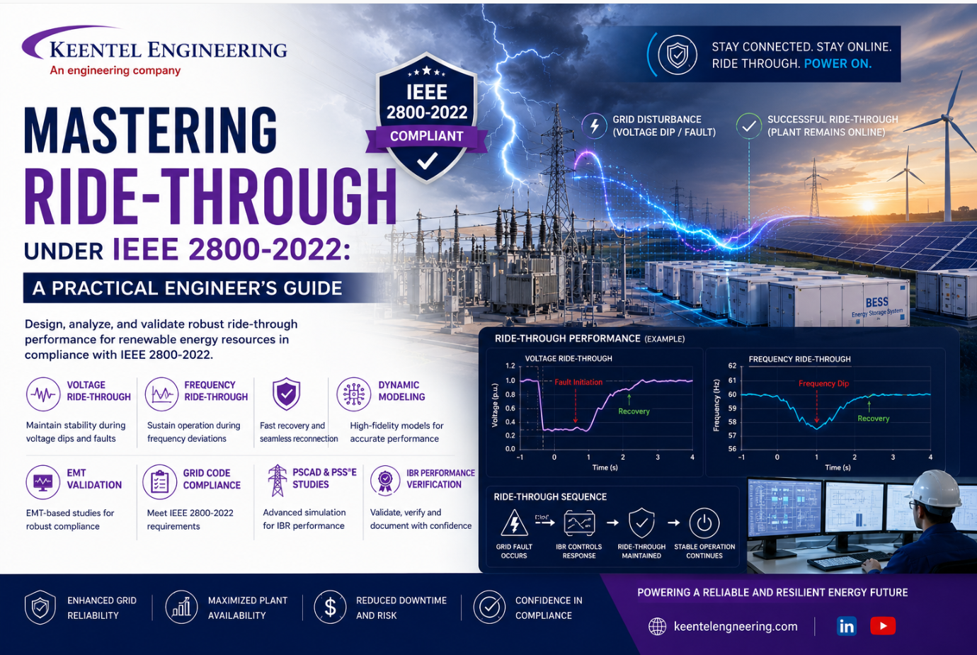


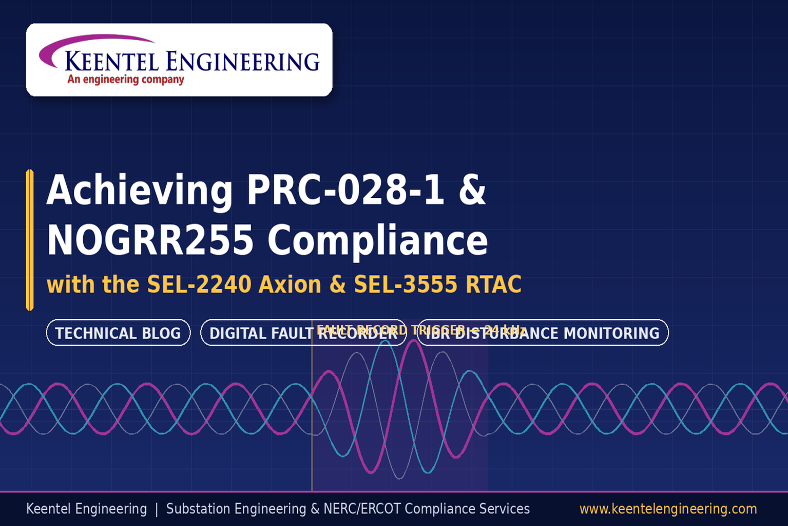
Learn how to achieve PRC-028-1 and ERCOT NOGRR255 compliance using the SEL-2240 Axion and SEL RTAC for disturbance monitoring, DFR engineering, and IBR facilities.
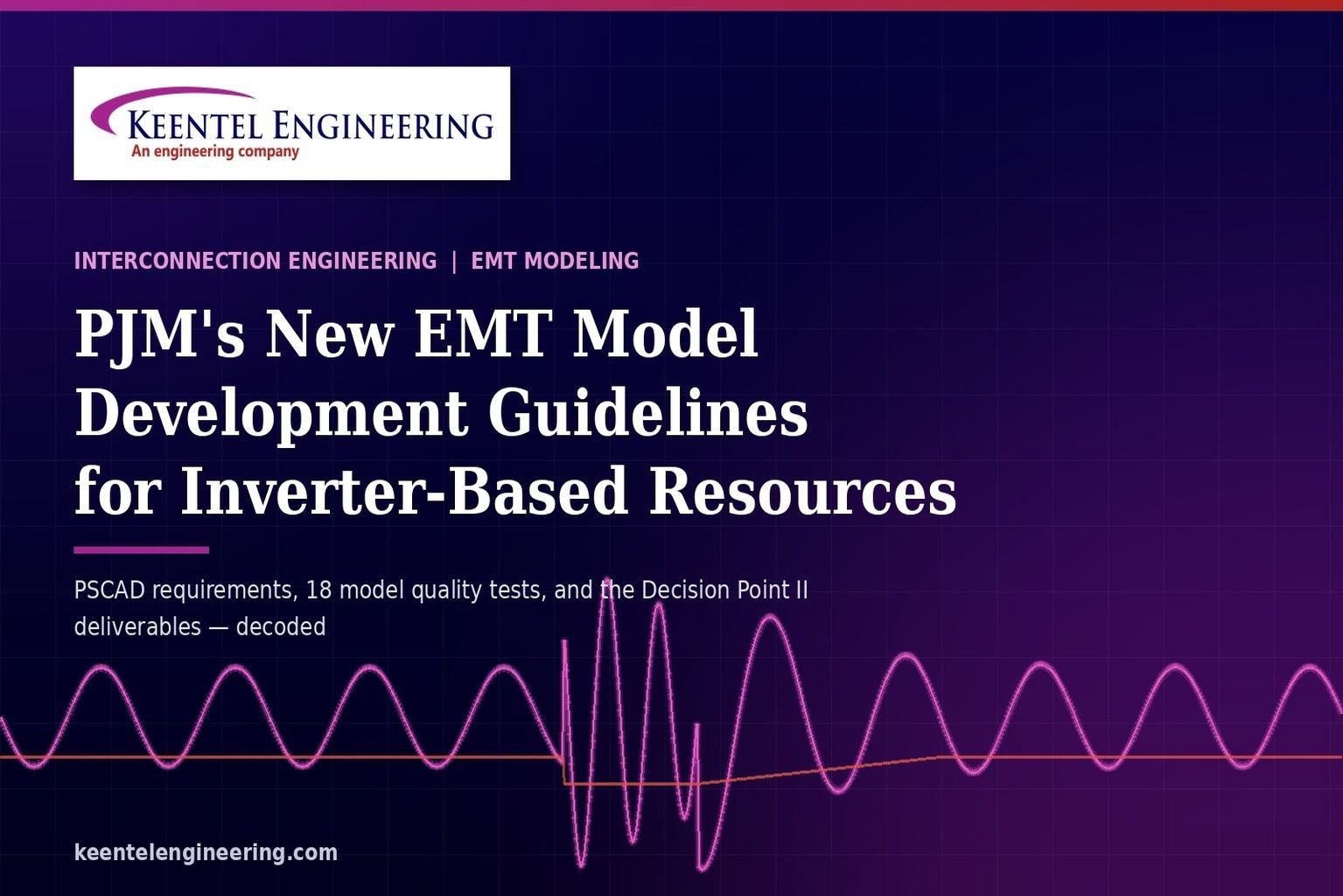
Learn PJM EMT model development requirements for inverter-based resources, including PSCAD modeling, benchmark testing, EMT studies, and Decision Point II compliance.
Master power transformer testing and commissioning with expert guidance on TTR, winding resistance, insulation testing, impedance tests, CT verification, and safe energization.
Discover fast real-time EMT simulation for low-inertia power systems, HIL testing, PSCAD modeling, cloud-based EMT, OEM controller integration, and transient stability assessment.
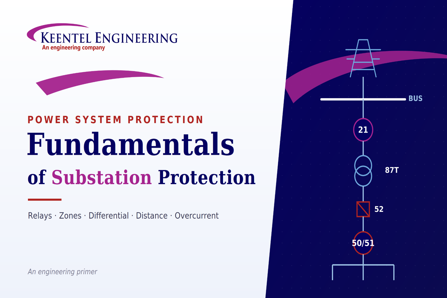
Learn substation protection, protective relaying, relay coordination, fault analysis, and power system protection fundamentals.
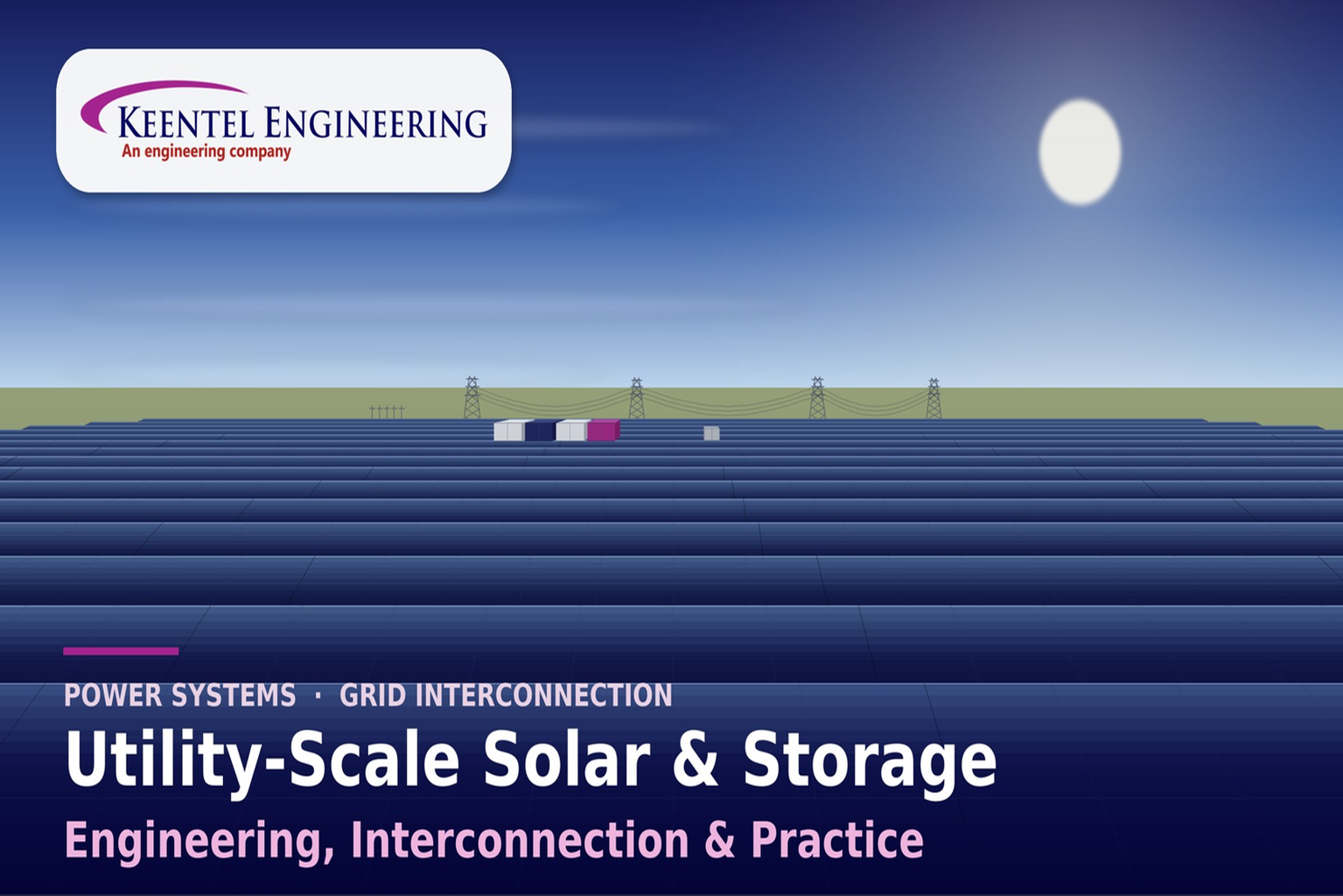
Learn utility-scale solar engineering, battery storage integration, grid interconnection, power system studies, and commissioning best practices.
WHITE PAPER |Learn data center design, power infrastructure, cooling systems, redundancy, and grid interconnection to build reliable, efficient facilities.
Learn how transmission line design progresses from 30% to IFC, covering clearance, sag-tension, structures, foundations, and engineering best practices.
Learn how the AP1000 supply chain, combined operating licenses, nuclear grid interconnection, transmission planning, and power system studies. for success.


