


A Coordinated Electric System Interconnection Review—the utility’s deep-dive on technical and cost impacts of your project.

Challenge: Frequent false tripping using conventional electromechanical relays
Solution: SEL-487E integration with multi-terminal differential protection and dynamic inrush restraint
Result: 90% reduction in false trips, saving over $250,000 in downtime

Category Metric
VPP capacity (Lunar Energy) 650 MW
Lunar funding raised US$232 million
Data center BESS example 31 MW / 62 MWh
ERCOT grid-scale batteries 15+ GW
LDES tenders (H1 2026) Up to 9.3 GW
Lithium-ion share of LDES by 2030 77%
FEOC initial threshold 55%
BESS tariff rate (2026) ~55%
Capacity gain from analytics 5–15%

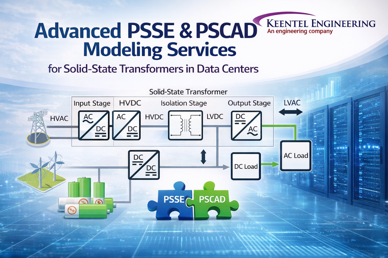
Advanced PSSE & PSCAD Modeling Services for Solid-State Transformers (SST) in Data Centers

By Keentel Engineering

Advanced PSSE and PSCAD modeling services for solid-state transformers in data center power systems
Calendar icon. D

Apr 7, 2026  | blog

Introduction: The Future of Power is Digital and Complex

As data centers scale to meet global digital demand, traditional power architectures are reaching their limits. Enter the Solid-State Transformer (SST) a transformative technology enabling MVAC to LVDC conversion, high efficiency, and seamless integration with energy storage systems.


However, deploying SST-based systems is not just an engineering challenge it is a modeling and validation challenge.


At Keentel Engineering, we specialize in delivering high-fidelity PSSE (RMS) and PSCAD (EMT) modeling services that help OEMs, developers, and utilities confidently deploy next-generation power systems.


Why SST Modeling is Critical for Data Center Applications

SST-based architectures introduce:


  • Fast dynamic behavior driven by controls 
  • Bidirectional power flow with BESS integration 
  • Nonlinear responses during faults and disturbances 
  • Harmonic and flicker impacts due to switching electronics 


Without proper modeling, risks include:


  • Grid interconnection rejection 
  • Protection system miscoordination 
  • Voltage instability 
  • Non-compliance with IEEE standards 

Keentel Engineering’s Core Expertise

Keentel Engineering provides end-to-end modeling and simulation services tailored to SST and power electronics-based systems:

1. PSSE (RMS) Modeling Services


  • Load flow and steady-state modeling 
  • Dynamic model development (.dyr) 
  • User-defined model (UDM) development for converters 
  • Grid compliance and interconnection studies 


2. PSCAD (EMT) Modeling Services


  • Detailed switching models of SST and converters 
  • Control system implementation and tuning 
  • DC system and BESS modeling 
  • Transient and fault analysis 


3. RMS–EMT Model Alignment


  • Parameter consistency across platforms 
  • Steady-state matching 
  • Dynamic validation under fault and load conditions 
  • Documentation of RMS-to-EMT mapping 


4. Power Quality & Grid Compliance Studies


  • Harmonics analysis (IEEE 519) 
  • Flicker and voltage fluctuation (IEEE 1453) 
  • Fault current and protection response 
  • Large load ride-through validation

Typical SST-Based System Modeled by Keentel

A typical project includes modeling:

  • Utility MV interconnection 
  • MV switchgear and protection 
  • Solid-State Transformer (multi-stage conversion) 
  • DC bus and distribution 
  • Battery Energy Storage System (BESS) 
  • Large IT/data center loads 

This creates a hybrid AC/DC system requiring advanced simulation techniques.


Keentel’s Modeling Approach

Step 1: System Understanding & Data Acquisition


  • Review SST design, control philosophy, and system configuration 
  • Define modeling scope and assumptions 


Step 2: PSCAD EMT Model Development (High-Fidelity)


  • Build detailed SST model (converter + control) 
  • Simulate switching behavior and fast dynamics 


Step 3: PSSE RMS Model Development


  • Develop simplified equivalent model 
  • Implement user-defined dynamic models where required 


Step 4: Model Alignment & Validation


  • Match steady-state operating points 
  • Validate dynamic response under multiple scenarios 
  • Ensure consistency between EMT and RMS results 


Step 5: Simulation Studies


  • Ride-through performance 
  • Fault response 
  • Harmonics and flicker analysis 


Step 6: Deliverables & Documentation


  • Fully packaged models 
  • User guides and validation reports 
  • Ready-to-use datasets for EPCs and utilities 

Key Studies Performed by Keentel

Large Load Ride-Through


Ensures system stability during rapid load changes typical of data centers.


Fault Current & Protection Response


Evaluates system behavior under faults and validates protection coordination.


Harmonics Analysis (IEEE 519)


Assesses power quality impacts from converter-based systems.


Flicker Analysis (IEEE 1453)


Ensures voltage stability and compliance under fluctuating loads.


Challenges Keentel Solves

  • Translating complex converter behavior into RMS models 
  • Ensuring PSSE and PSCAD alignment 
  • Modeling low fault current systems 
  • Capturing fast transient responses 
  • Delivering utility-acceptable models 

Why Choose Keentel Engineering?

  • 30+ years of combined power system expertise 
  • Deep experience in IBR, BESS, and converter modeling 
  • Expertise in PSSE, PSCAD, TSAT, and EMT simulations 
  • Proven success in grid compliance and interconnection studies 
  • Ability to deliver customer-ready modeling packages 

Work with Keentel Engineering

If you're developing:


SST systems 

BESS-integrated solutions 

Data center power infrastructure 


Keentel Engineering can support your project from model development to grid validation.


 In-Depth FAQ (Technical & Practical)

  • 1. Why are both PSSE and PSCAD required for SST modeling?

    PSSE and PSCAD serve different but complementary purposes:


    PSSE (RMS) is used for: 


    • Grid-level simulations 
    • Steady-state and transient stability 
    • Utility and ISO studies 

    PSCAD (EMT) is used for:


    • Fast transient behavior 
    • Detailed converter switching 
    • Harmonics and control interactions 

    SSTs are control-driven devices, meaning their behavior changes depending on time scale. PSCAD captures the physics, while PSSE provides system-level integration.


    Without both, the model is incomplete and may not be accepted by utilities.


  • 2. What makes SST modeling more complex than traditional transformers?

    Traditional transformers are passive devices governed by electromagnetic laws. SSTs, however:


    • Use power electronics and digital controls 
    • Exhibit nonlinear and fast dynamic behavior 
    • Have limited fault current contribution 
    • Interact strongly with both grid and load 

    This requires:


    • EMT-level modeling for accuracy 
    • Advanced control system representation 
    • Iterative validation 

  • 3. What is RMS–EMT model alignment and why is it important?

    RMS–EMT alignment ensures that:


    • Both models produce the same steady-state results 
    • Dynamic responses are consistent across simulations 
    • Parameters are mapped correctly 

    This is critical because:


    • Utilities rely on PSSE models 
    • Engineers validate behavior in PSCAD 

    Misalignment can lead to incorrect conclusions and project delays.


  • 4. Do SST systems contribute fault current like traditional systems?

    No. SSTs typically:

    • Limit fault current using control systems 
    • Do not provide high short-circuit currents 

    This impacts:

    • Protection system design 
    • Relay coordination 
    • Fault detection strategies 

    Specialized modeling is required to accurately represent this behavior.


  • 5. How are harmonics evaluated in SST systems?

    Harmonics are analyzed using PSCAD by:

    • Running time-domain simulations 
    • Extracting frequency components 
    • Comparing results against IEEE 519 limits 

    Mitigation strategies may include:

    Filters 

    • Control tuning 
    • System design modifications 

  • 6. What type of data is required to build accurate SST models?

    Key inputs include:

    • Electrical parameters (impedance, ratings) 
    • Control algorithms and logic 
    • Converter topology 
    • Protection settings 
    • Load characteristics 

    The quality of the model is directly tied to the quality of input data.


  • 7. How long does a typical SST modeling project take?

    Typical timelines:

    • 8–14 weeks depending on complexity 
    • Multiple iterations for validation 
    • Additional time if controls are not fully defined 

  • 8. Can these models be reused for future projects?

    Yes. Keentel develops modular, reusable modeling packages that:

    • Can be adapted for different sites 
    • Are shareable with EPCs and utilities 
    • Reduce future engineering effort 

  • 9. What standards are typically evaluated?

    Common standards include:

    • IEEE 519 → Harmonics 
    • IEEE 1453 → Flicker 
    • NERC / ISO-specific grid codes 
    • Interconnection requirements 

  • 10. Why should OEMs partner with Keentel Engineering?

    OEMs benefit from:

    • Independent validation of their technology 
    • Faster interconnection approvals 
    • High-quality, customer-ready models 
    • Reduced risk in deployment 

    Keentel acts as a technical bridge between innovation and grid compliance.


Conclusion

Solid-State Transformers are redefining how power is delivered especially in data centers. But their successful deployment depends on accurate, validated modeling across both RMS and EMT domains.


Keentel Engineering brings the expertise, tools, and experience needed to deliver high-fidelity modeling solutions that enable confidence, compliance, and scalability.


A smiling man with glasses and a beard wearing a blue blazer stands in front of server racks in a data center.

About the Author:

Sonny Patel P.E. EC

IEEE Senior Member

In 1995, Sandip (Sonny) R. Patel earned his Electrical Engineering degree from the University of Illinois, specializing in Electrical Engineering . But degrees don’t build legacies—action does. For three decades, he’s been shaping the future of engineering, not just as a licensed Professional Engineer across multiple states (Florida, California, New York, West Virginia, and Minnesota), but as a doer. A builder. A leader. Not just an engineer. A Licensed Electrical Contractor in Florida with an Unlimited EC license. Not just an executive. The founder and CEO of KEENTEL LLC—where expertise meets execution. Three decades. Multiple states. Endless impact.

Four workers in safety vests and helmets stand with arms crossed near wind turbines.

Let's Discuss Your Project

Let's book a call to discuss your electrical engineering project that we can help you with.

Man in a blazer and open shirt, looking at the camera, against a blurred background.

About the Author:

Sonny Patel P.E. EC

IEEE Senior Member

In 1995, Sandip (Sonny) R. Patel earned his Electrical Engineering degree from the University of Illinois, specializing in Electrical Engineering . But degrees don’t build legacies—action does. For three decades, he’s been shaping the future of engineering, not just as a licensed Professional Engineer across multiple states (Florida, California, New York, West Virginia, and Minnesota), but as a doer. A builder. A leader. Not just an engineer. A Licensed Electrical Contractor in Florida with an Unlimited EC license. Not just an executive. The founder and CEO of KEENTEL LLC—where expertise meets execution. Three decades. Multiple states. Endless impact.

Leave a Comment

Related Posts

ERCOT Batch Zero large load interconnection guide
By SANDIP R PATEL July 5, 2026
Learn ERCOT Batch Zero requirements, large load interconnection, ride-through standards, dynamic modeling, compliance timelines, and grid approvals.
PRC-028-1 and NOGRR255 compliance with SEL-2240 Axion and SEL-3555 RTAC
By SANDIP R PATEL July 5, 2026
Learn how to achieve PRC-028-1 and ERCOT NOGRR255 compliance using the SEL-2240 Axion and SEL RTAC for disturbance monitoring, DFR engineering, and IBR facilities.
PJM EMT modeling guidelines for inverter-based resources
By SANDIP R PATEL July 3, 2026
Learn PJM EMT model development requirements for inverter-based resources, including PSCAD modeling, benchmark testing, EMT studies, and Decision Point II compliance.
Power transformer testing and commissioning
By SANDIP R PATEL July 2, 2026
Master power transformer testing and commissioning with expert guidance on TTR, winding resistance, insulation testing, impedance tests, CT verification, and safe energization.
Fast real-time EMT simulation for low-inertia power systems
By SANDIP R PATEL July 2, 2026
Discover fast real-time EMT simulation for low-inertia power systems, HIL testing, PSCAD modeling, cloud-based EMT, OEM controller integration, and transient stability assessment.
Fundamentals of substation protection and power system relays
By SANDIP R PATEL June 30, 2026
Learn substation protection, protective relaying, relay coordination, fault analysis, and power system protection fundamentals.
Utility-scale solar and battery storage engineering infrastructure
By SANDIP R PATEL June 30, 2026
Learn utility-scale solar engineering, battery storage integration, grid interconnection, power system studies, and commissioning best practices.
Data center design engineering with grid-to-rack power and cooling
By SANDIP R PATEL June 29, 2026
WHITE PAPER |Learn data center design, power infrastructure, cooling systems, redundancy, and grid interconnection to build reliable, efficient facilities.
Transmission line engineering from 30% design to IFC
By SANDIP R PATEL June 29, 2026
Learn how transmission line design progresses from 30% to IFC, covering clearance, sag-tension, structures, foundations, and engineering best practices.