
A Coordinated Electric System Interconnection Review—the utility’s deep-dive on technical and cost impacts of your project.
Challenge: Frequent false tripping using conventional electromechanical relays
Solution: SEL-487E integration with multi-terminal differential protection and dynamic inrush restraint
Result: 90% reduction in false trips, saving over $250,000 in downtime
The three operating regions you have to design to
| Device | Output vs voltage | Response | Best suited to | Main limitations |
|---|---|---|---|---|
| Mechanically switched capacitor or reactor | Proportional to voltage squared | Seconds; discrete steps; limited switching operations per day | Steady-state reactive supply, voltage profile, loss reduction | No dynamic capability; step voltage change on switching; capability collapses when most needed |
| Static var compensator | Capacitive branches proportional to voltage squared | A few cycles; continuously controllable | Continuous control where cost matters and deep voltage support is not the driver | Square-law capability loss; harmonic filters are part of the plant and interact with the network |
| STATCOM | Approximately proportional to voltage — constant current capability | One to two cycles closed loop; converter response faster still | Voltage stability margin, weak interconnections, fast disturbance recovery, flicker and unbalance compensation | Higher capital cost; converter losses; adds a converter and its control dynamics to the network |
| Synchronous condenser | Governed by machine capability and excitation | Excitation response in the hundreds of milliseconds; inherent inertial response instantaneous | System strength and inertia, short-circuit contribution, black start support | Rotating plant with maintenance and losses; slower controlled response than a converter |
| STATCOM with energy storage | Reactive as a STATCOM, plus real power within the storage rating | As STATCOM for reactive; real power limited by storage | Where a real power deficiency is part of the problem | Cost and complexity of the storage; different failure and maintenance profile |
MOD-025 Reactive Capability Testing in the PJM Footprint: What Every Generator Owner Needs to Know

September 20, 2026 | Blog
By Keentel Engineering — NERC Compliance Practice
Every five years, the owner of a large generator connected to the bulk electric system has to prove two things to the people who plan and operate the grid: how much real power the unit can really deliver, and how much reactive power it can push out or pull in while doing it. That proof is required by NERC Reliability Standard MOD-025-2. If your plant sits inside the PJM Interconnection footprint — thirteen states and the District of Columbia, from Chicago to the Atlantic coast there is a second layer on top of the NERC standard: PJM's own reactive capability testing procedure, written into PJM Manual 14D, Attachment E, and administered through PJM's eDART system.
The two are designed to be satisfied by a single test. In practice, generator owners who treat them as one and the same tend to run into trouble, because PJM asks for things the NERC standard does not, scores the results differently, and works to a shorter clock. This article walks through both, explains where they diverge, lays out the process step by step in plain language, and closes with a technical FAQ drawn from the questions we hear most often from the utilities, independent power producers, and renewable developers we support.
Keentel Engineering has spent three decades in grid interconnection and NERC compliance engineering. We have planned, witnessed, analyzed, and filed reactive capability verifications for conventional steam and combustion turbine plants, combined-cycle facilities, hydro, and inverter-based solar, wind, and battery resources across multiple ISOs. What follows is what we have learned.
Part 1 — Why the test exists
Reactive power is what holds grid voltage where it needs to be. A generator that can deliver a large lagging (over-excited) reactive output raises voltage on the system around it; one that can absorb reactive power (leading, under-excited) pulls voltage down. Transmission planners build their models of the grid on the assumption that each generator can deliver the reactive range shown in its capability curve — the familiar "D-curve" of Mvar against MW and system operators dispatch voltage support in real time on the same assumption.
If those assumptions are wrong, the consequences show up during the worst moments: a hot summer afternoon when voltage is sagging and the units the operators are counting on turn out to have twenty fewer Mvar than the model says. The 2003 Northeast blackout investigation identified inaccurate generator reactive capability data as one of the contributing factors, and MOD-025 is one of the standards that came out of the resulting push to make the models match reality.
The standard therefore asks each Generator Owner to periodically demonstrate, by test or by qualifying operational data, the actual real and reactive capability of each applicable unit, and to send the results to the Transmission Planner so the planning models can be corrected.
Part 2 — What NERC MOD-025-2 requires
MOD-025-2 has three requirements. Only two apply to Generator Owners; the third applies to Transmission Owners with synchronous condensers.
Requirement R1 covers Real Power: verify the unit's real power capability per Attachment 1 and submit the results to the Transmission Planner within 90 calendar days.
Requirement R2 covers Reactive Power: verify the unit's reactive power capability per Attachment 1 and submit the results to the Transmission Planner within 90 calendar days.
Applicability is determined by size and connection. An individual generating unit is covered if it exceeds 20 MVA gross nameplate and is directly connected to the bulk electric system. A generating plant is covered if its aggregate gross nameplate exceeds 75 MVA and it is directly connected. Within an applicable plant, every unit over 20 MVA must be verified individually; smaller units may be grouped. For wind and solar facilities, the standard treats the whole plant at a common point of interconnection or under a common control system as one facility.
Periodicity is at least once every five years, with an absolute cap of 66 calendar months between verifications. Three events trigger an earlier re-verification within 12 months: a change of more than 10 percent in the verified capability that is expected to last more than six months; commercial operation of a new unit; or return of a unit from a long-term shutdown of more than five years.
Attachment 1 is the technical heart of the standard. Its key provisions are:
The first verification under the standard must be a staged test. After that, operational data may be used instead, but only if it meets conditions: the data must come from the two years before the verification date, must include all the required measurements, and must demonstrate at least 90 percent of the capability shown in a previous staged test that itself reached at least 50 percent of the capability curve. If the prior staged test was restricted — capacitor banks out of service, for example — the next verification must again be staged.
For a synchronous unit, the maximum real power and lagging reactive power must be held for a minimum of one hour. Reactive power must then be verified at four points: over-excited (lagging) and under-excited (leading) at maximum real power, and lagging and leading at the minimum real power at which the unit normally operates. At each point the value is recorded as soon as a limiting element is reached — the exciter limiter, a temperature limit, a voltage limit — and the reason is noted.
For a variable resource such as wind or solar, the verification is done at whatever maximum output is available at the time, with at least 90 percent of the inverters or turbines on line, and the minimum-load reactive points are not required.
All auxiliary equipment needed for normal operation must be in service, and the automatic voltage regulator must be in service and in automatic for the reactive verification. The test should be coordinated with the Transmission Operator so that the plant's system bus is held at or near its voltage schedule.
The data that must be recorded includes gross MW and Mvar at the end of the verification period; the Transmission Operator's voltage schedule; generator step-up transformer high-side and low-side voltage; ambient conditions relevant to output correction (air temperature, humidity, cooling water temperature); date and start/end times in hours and minutes; GSU ratio and tap; and whether the data came from a staged test or operational data. A simplified one-line diagram must show the sources of auxiliary real and reactive power, the transformers, and the direction of reactive flow, and auxiliary load may be calculated where it is not metered.
Attachment 2 is the reporting form. The Generator Owner may use it as printed or submit an equivalent form that captures everything in Attachment 1. It carries the verification checkboxes, the one-line with measurement points labeled A (generator terminals) through F (net at the point of interconnection), a voltage/MW/Mvar table for those points, a "data recorded" versus "last verification" comparison, and a block for dates, times, voltages, transformer data, ambient conditions, and remarks.
Evidence and retention are straightforward: the completed form, the underlying data, and dated proof that the form was submitted within 90 days. The Generator Owner must keep the latest form, its data, and the submittal evidence since the last compliance audit.
Part 3 — What PJM adds on top
PJM is the Transmission Planner and the Reliability Coordinator for its footprint, so the MOD-025 submittal goes to PJM. But PJM did not simply adopt the NERC form. It has its own reactive testing program, older than MOD-025, that lives in Manual 14D, Attachment E, and it expressly states that Attachment E is intended to align with MOD-025 so that one test satisfies both — while noting that "certain differences remain." Those differences matter.
The test has a season
Attachment E requires the maximum lagging test at maximum real power to be conducted between May 1 and September 30, preferably on weekdays between noon and 6:00 p.m. Eastern. The logic is simple: PJM wants the lagging capability demonstrated under summer conditions, when the system needs it most. The maximum leading test at minimum load is preferred during off-peak hours (11:00 p.m. to 7:00 a.m.) for fossil steam, nuclear, combined-cycle, and hydro units; for simple-cycle combustion turbines and other types the owner picks the time. NERC has no seasonal requirement at all.
The measurement basis is different
MOD-025 wants gross values at the generator terminals and net values at the point of interconnection. PJM wants the reactive capability at the low side of the generator step-up transformer, excluding any station service load fed from the unit's terminal bus, because that is how PJM's energy management system models the unit. Attachment E therefore asks for readings at four places: the generator terminals (gross), the auxiliaries, the GSU primary (low-side net after auxiliaries), and the GSU secondary (high-side net). A well-planned test captures all four from one data set; a test planned only to the NERC form will leave the PJM value to be reconstructed afterward.
PJM scores the result against a stated number
After the test, PJM's Reactive Testing group compares two of the four points — maximum lagging at maximum MW and maximum leading at minimum MW — against the capability curve the owner has on file in eDART. Within plus or minus 5 percent is a pass with no action. More than 5 percent above triggers a request to raise the curve. More than 5 percent below means the capability was not demonstrated, and the owner must either permanently reduce the curve or retest — unless an external limitation was reported and logged during the test. NERC does no such scoring; it only requires that the test be done and the data submitted.
That external-limitation clause is the single most important sentence in Attachment E for a Generator Owner. If the unit cannot reach its stated capability because of system conditions — most commonly, high transmission voltage that pushes the generator into its terminal-voltage limiter before it reaches its rotor limit — the plant or its market operations center must tell the Transmission Owner and the PJM Reliability Engineer before the test is completed. The Reliability Engineer logs the limitation on the test ticket and no further action is taken. Discovering the same limitation afterward puts the owner into the reduce-or-retest branch, and there is no appeal.
The notification chain is fixed
Attachment E prescribes exactly who is told what and when. Before the test is even scheduled, the plant, the market operations center, and PJM must verify that the telemetered MW and Mvar values agree; if PJM's post-test analysis finds inconsistencies, a retest can be required. Any maintenance affecting reactive capability must be complete and its eDART tickets closed. The eDART MVAR Test ticket must be filed by noon three business days before the test, which notifies PJM Dispatch, the Reliability Engineer, and the Transmission Owner. The Reliability Engineer must be contacted at least three hours before the start so a real-time study can be run; the Transmission Owner contacts the Reliability Engineer at least 2 hours 15 minutes before. Thirty minutes' notice goes to the Transmission Owner and PJM dispatch before each real-time change. Reactive step changes are generally limited to 100 Mvar at a time. Cancellations and reschedules go to the Reliability Engineer as soon as possible.
The clock is shorter
NERC allows 90 calendar days to submit the Attachment 2. PJM requires the Reactive Result ticket in eDART within 30 calendar days of each test portion, all portions within six months, and a separate notification for each test day. If a new capability curve is required and the owner does not supply it within 30 days, PJM may set it from the test results itself.
Multi-unit stations test one facility at a time
Attachment E says stations with more than one facility requiring testing shall test only one at a time, with the others operating normally. Owners with units that share a generator step-up transformer, and who therefore want to test them together, need to state that in the ticket and clear it with PJM's Reactive Testing group in advance.
There is a separate real-power process
PJM handles the real-power portion of MOD-025 through a different channel from the reactive portion. The reactive results go into eDART as a Reactive Result ticket. The real-power Attachment 2 data is emailed to PJM's real-power testing mailbox with a prescribed subject line, and the test itself is coordinated through an eDART Informational or Governor ticket with a call to PJM Dispatch so the unit is logged as "Testing." PJM's own summer and winter capability verification for capacity-market purposes is a third process under a different manual, and it is not the same thing as MOD-025.
Part 4 — The process, step by step, in plain language
Here is how a PJM-footprint MOD-025 verification actually unfolds, from the first planning call to the last filing, described for someone who has never been through one.
Before the test — roughly two to four weeks out
Step 1. Find out when you are due. Pull the date of the last verification for each unit. Add 66 months. That is your hard deadline. Then look at PJM's calendar: if the full-load lagging test has to happen between May 1 and September 30, work backward to a test date that fits both.
Step 2. Get the numbers you will be judged against. Ask your market operations center for the current eDART capability curve for each unit. This is the value PJM will compare your test to. If you know before the test that the unit is likely to fall short of it — because of a known limiter setting, a known bus-voltage problem, or a capacitor bank that is out — you want to know now, not after.
Step 3. Understand your plant's electrical arrangement. Pull the one-line and answer three questions. Where is the gross metering — at the generator terminals or the GSU high side? Where does station service come from — off the unit under test, or off a different unit or a separate feed? And does the unit share a GSU with another unit? The answers determine how you will separate gross from net and whether you can read the net value straight off a meter or will have to calculate it.
Step 4. Read back the exciter limiter settings. The test will drive the unit to its limiters. Confirm what they are — Volts/Hz, over-excitation, under-excitation — and that they match the last protection coordination study. This is also the point to confirm that no operator action at either limit can trip the unit; the limiters exist precisely so that it cannot.
Step 5. Verify telemetry. Sit the plant, the market operations center, and the PJM Reliability Engineer down together and confirm that the MW and Mvar values each of them sees for the unit agree. Record the date and time; it goes on the form.
Step 6. Close out maintenance. Any open work affecting reactive capability must be finished and its eDART tickets cleared.
Step 7. File the ticket. By noon three business days before the test, the market operations center files an eDART MVAR Test ticket for each unit — test types, duration, and any special conditions such as testing a GSU pair together or requesting that the Transmission Owner hold the bus at the low end of the voltage schedule. File the Informational or Governor ticket for the real-power portion at the same time.
Step 8. Ask for voltage. This is the step most owners miss. Attachment E allows deviations from the voltage schedule with PJM and Transmission Owner agreement, and specifically allows other units at the same site to run at the edge of their bandwidth to help. If your lagging limit is a terminal-voltage limiter, every kilovolt the transmission bus is held lower is worth several Mvar of demonstrated capability. Ask for it in the ticket.
On the test day
Step 9. Pre-job brief. Everyone in the control room — operator, shift supervisor, test engineer, and whoever is talking to PJM — walks through the sequence, the stop rules, and who calls whom. Three rules govern the day: only the operator touches a control; the AVR stays in automatic with all limiters on; the shift supervisor can stop any step at any time.
Step 10. Calls. Three hours before start, the market operations center phones the PJM Reliability Engineer to start the real-time study and confirms the Transmission Owner has called too. Thirty minutes before start, it phones PJM Dispatch and the Transmission Owner. The unit is logged as "Testing."
Step 11. Minimum-load points. With the unit at its normal minimum load, the operator raises the AVR setpoint in small steps until the lagging limiter holds, the values are recorded, and the unit returns toward unity. The operator then lowers the setpoint until the under-excitation limiter holds, values are recorded, and the unit returns toward unity. Each point takes about ten minutes.
Step 12. The lagging hour. The unit is brought to maximum real power — for a combustion turbine, that is base load on temperature control with the inlet guide vanes fully open; for a steam unit, the normal maximum. The operator raises the AVR setpoint until the lagging limiter holds, and the clock starts. For the next hour, the operator's only job is to keep the unit at the limiter: as transmission voltage moves, the unit will give back or take up Mvar at constant terminal voltage, and every setpoint adjustment is logged. Plan for seventy minutes so there is a clean sixty inside. Real power is recorded through the same hour — this single hold satisfies both the reactive and the real-power verification.
Step 13. The external-limitation call. Midway through the hour, if the unit is sitting at its terminal-voltage limiter with the transmission bus high and its Mvar below the stated capability, the market operations center tells the Reliability Engineer and the Transmission Owner so, asks whether the bus can be lowered, and asks that the limitation be logged. This must happen before the point is closed out.
Step 14. The leading point at full load. Still at maximum real power, the operator lowers the AVR setpoint until the under-excitation limiter holds, values are recorded, and the unit returns toward unity.
Step 15. Close out. The market operations center calls PJM Dispatch and the Transmission Owner to report the test complete. Data sheets are checked against the historian and signed by the shift supervisor and the test engineer. The historian export — one-minute data for the whole window — is pulled and handed over.
After the test
Step 16. Analysis. The test engineer computes the one-hour average of the lagging point from the one-minute historian data (this is how PJM computes its own figure from telemetry, and using a different method invites a mismatch), separates gross from net, calculates or reads the GSU losses, and compares every point to the stated eDART capability and to the previous verification.
Step 17. The PJM filings — 30 days. The market operations center enters a Reactive Result ticket in eDART for each unit, emails the real-power Attachment 2 data to PJM's real-power testing mailbox, and, if any point is more than 5 percent above or below the stated curve, files a MVAR ticket with the "New Default" box checked and the proposed new eight-point capability curve.
Step 18. The NERC filing — 90 days. The MOD-025 Attachment 2 (or equivalent) for each unit goes to PJM as Transmission Planner. In practice the eDART Reactive Result ticket and the real-power email satisfy this, but the owner should keep the eDART confirmations and the sent email as the dated evidence the standard requires.
Step 19. PJM's letter. Within about 60 days PJM issues a test letter per unit stating whether each point was within 5 percent, above, or below, and what action if any is required. That letter goes into the compliance file next to the Attachment 2, the data, and the submittal evidence.
Step 20. Set the next date. Sixty-six months from the test date is the outside limit for the next verification. Put it in the compliance calendar now.
Part 5 — What actually limits a generator's reactive output
Owners are often surprised when a unit rated for 50 Mvar lagging demonstrates 35 on test day and PJM cuts the curve. Almost always, the reason is not the machine.
A synchronous generator's lagging capability is bounded by three things: the rotor (field) thermal limit, the over-excitation limiter that protects it, and the terminal voltage the exciter is allowed to reach. On most units the exciter has a Volts/Hz or over-voltage limiter set around 105 percent of rated terminal voltage. When the transmission bus is running high — and in PJM it often is on a summer afternoon — the generator reaches that terminal-voltage ceiling long before it reaches its rotor limit, because pushing more Mvar into an already-high bus requires more terminal voltage. The unit is then said to be "voltage-limited": it is holding 1.05 per unit and can push no more, regardless of what the D-curve says the rotor could do.
This has three consequences for the test. First, the demonstrated lagging capability depends on the transmission voltage on the day, which is why Attachment E allows the owner to ask for a lower schedule and why Step 8 above matters so much. Second, during a one-hour hold the unit's Mvar will drift down whenever the bus rises and back up whenever it falls, at constant terminal voltage, which is normal and should be logged rather than fought. Third, when the unit is voltage-limited, the situation is by definition an external limitation, and the owner must say so to PJM before the point closes — because that is the difference between a logged limitation and a permanently reduced curve.
On the leading side, the under-excitation limiter is almost always the stop, and it is set to keep the unit clear of the stator core-end heating limit and the loss-of-excitation relay. Leading capability is therefore stable from test to test and rarely a source of dispute.
For
inverter-based resources the picture is different. Reactive capability is set by the inverter's rated MVA and its control mode, is usually symmetric, and is not very sensitive to transmission voltage until the inverter's own terminal-voltage limits are reached. The test is simpler, but the aggregation across hundreds of inverters, the 90 percent availability requirement, and the collector-system losses between inverter and POI become the engineering questions.
Part 6 — Building the eight-point curve
PJM models each unit's reactive capability as a table of up to eight MW points, each with a minimum (leading) and maximum (lagging) Mvar, on the GSU low-side basis. A test produces measured values at only two MW levels. The curve is built from them.
Points 1 and 2 bracket the minimum-load test point: Point 1 at or just below the typical minimum economic output, Point 2 at the tested minimum load. Points 3 through 6 are intermediate MW levels — usually the unit's dispatch-curve breakpoints — with Mvar interpolated between the tested minimum-load and maximum-load values, which is a fair representation because both the under-excitation limiter and the terminal-voltage limiter are nearly flat with MW. Point 7 is the tested maximum load. Point 8 is the maximum possible output under ideal (winter) ambient, extrapolated along the shape of the manufacturer's capability curve. Attachment D permits engineering judgment where test data does not exist at a given MW point. The curve must have MW increasing from Point 1 to Point 8 and lagging Mvar at or above leading Mvar at every point.
Part 7 — Technical FAQ
Is the one-hour hold required at every test point?
No. MOD-025-2 Attachment 1 item 2.1.1 requires the maximum real power and lagging reactive power to be held for a minimum of one hour; Attachment E's fossil matrix requires the same. The other three reactive points are recorded as soon as the limit is reached and the reading is steady — typically a few minutes each.
Does the hour satisfy the real-power verification too?
Yes. The real power held during the lagging hour, with the ambient conditions recorded, is the R1 verification. There is no separate real-power hold.
What if the unit comes off the limiter during the hour?
The hour restarts. This is why experienced test engineers plan seventy minutes rather than sixty, and why the operator's only task during the hold is to keep the AVR at the limiter.
Which value goes on the form — the peak, the end, or the average?
MOD-025 Attachment 2 asks for values at the end of the verification period. PJM scores the one-hour average of its own one-minute telemetry. Report both, from the same historian record, and make sure your average is computed the same way PJM's is. Spot readings averaged by hand have caused real disputes.
Our two units share a GSU. Can we test them together?
Attachment E says one facility at a time at a multi-facility station, but PJM has accepted concurrent testing of GSU pairs when it is stated in the ticket and one unit runs leading while the other holds its lagging hour. The benefit is real: with the pair near unity at the point of interconnection, the test does not push up the local bus and erode the lagging unit's own headroom. Clear it with PJM's Reactive Testing group first.
How do we get individual net values if there is only one high-side meter per GSU?
Either split the high-side reading between the two units in proportion to their gross MW and say so in Remarks, or calculate each unit's GSU loss from the nameplate impedance and subtract it from the unit's gross reading. MOD-025 Attachment 1 item 2.4 explicitly allows losses to be estimated from impedance. Cross-check the calculation against the meter at any moment when only one unit is loaded.
Station service on our plant comes from a different unit. What is Point B?
Zero for the unit under test, with an explanation on the form and a lineup screen capture as evidence. The low-side net then equals the gross. The station service load appears on the unit that actually supplies it.
Can we use operational data instead of a staged test?
Only after the first staged verification, only from the two years before the verification date, only with all the required measurements, and only if it shows at least 90 percent of a prior staged test that reached at least 50 percent of the capability curve. In practice, few plants have historian data that meets all of these at once, and most owners stage the test.
The unit was voltage-limited and fell short of the eDART number. What now?
If the market operations center told the PJM Reliability Engineer and the Transmission Owner during the test and the limitation was logged, no action is required. If it did not, PJM will treat the shortfall as undemonstrated capability and the owner must reduce the curve or retest. This is the single most expensive omission in the whole process.
Which signals must be hardwired, and which can go over a protocol?
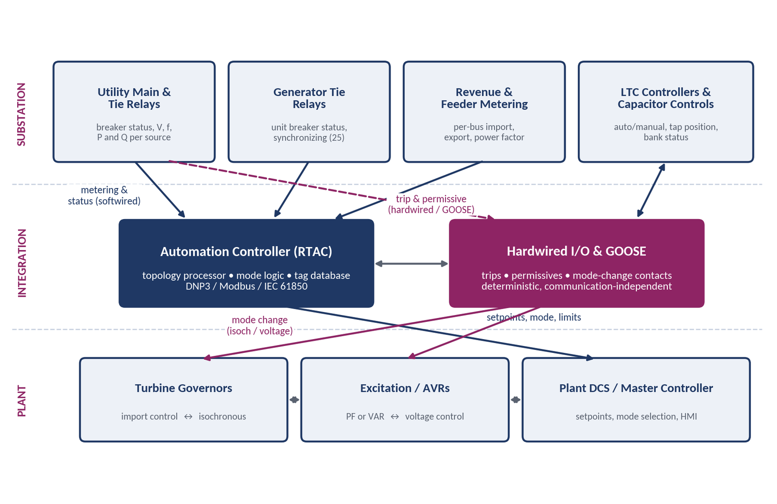
Decide by consequence. Anything whose failure would prevent a trip or allow an unsafe closure — trips, mode-change commands, close permissives, breaker status used in protection logic — should be hardwired or carried over IEC 61850 GOOSE with defined performance. Metering, setpoints, mode selection and status display can be softwired over DNP3 or Modbus, provided every point has quality handling and a defined fail-safe value.
What does "AVR in service" mean on the form, and how is it evidenced?
The automatic voltage regulator must be in automatic (voltage-control) mode with its limiters enabled throughout the reactive verification. A screen capture of the exciter control panel at each test point — showing the regulator mode, the active limiter, and no fault codes — is the cleanest evidence.
We are a solar or wind plant. What changes?
The verification is at whatever maximum output is available on the day, the minimum-load reactive points are not required, and at least 90 percent of the inverters or turbines must be on line; if that cannot be met, document why, test anyway, and retest within six months of being able to reach 90 percent. The reactive test is of the plant at the point of interconnection, so collector-system and main transformer losses must be accounted for. PJM's Attachment E and Attachment D have specific provisions for inverter-based and energy storage resources.
Do we need the manufacturer's capability curve?
MOD-025 notes that a comparison to the manufacturer's D-curve is expected though not required, and PJM's post-test evaluation compares to the eDART curve, not the OEM curve. Have the OEM curve on file; if all you have is a calculated curve from a protection study, say so.
What does the compliance file need to contain?
The completed Attachment 2 or equivalent per unit; the underlying data (historian export, data sheets, screen captures); the eDART ticket records and PJM's test letter; the dated email or eDART confirmation proving submittal within 90 days; and the telemetry-verification and limiter read-back records. Keep it through the next audit.
How far out should we start?
Four weeks is comfortable. The binding constraints are the three-business-day eDART notice, the telemetry check that must precede scheduling, and the September 30 window for the lagging test. Owners who start in August for a September test are usually fine; owners who start in late September are not.
How Keentel Engineering helps
Over three decades, Keentel Engineering has supported utilities, independent power producers, conventional generation owners, and renewable developers through every stage of the MOD-025 and PJM Attachment E process: establishing the periodicity calendar across a fleet; reading the plant one-line and protection studies to plan the measurement points; writing the step-by-step test procedure in language the control room can execute; coordinating the eDART filings and the PJM and Transmission Owner notifications; witnessing the test and watching the live data so that limitations are reported when they must be; reconciling hand-recorded data against the historian; computing the net values and the eight-point curve; and preparing the Attachment 2, the eDART result data, and the compliance-file evidence package.
We also carry the lessons from one test into the next. The most common reasons a unit falls short — an unreported voltage limitation, a lagging average computed differently from PJM's, an overlapping test that pushed up the plant's own bus — are all avoidable with planning, and the difference between a demonstrated curve and a reduced one is usually decided before anyone touches the AVR.
If your plant is inside the PJM footprint and a MOD-025 verification is coming due, we would be glad to help you plan it.
Keentel Engineering Head Office: 400 N Ashley Dr STE #2600, Tampa, FL 33602 · (813) 389-7871 · contact@keentelengineering.com · keentelengineering.com Offices in Austin TX · Sacramento CA · Baltimore MD
References and Further Reading
- NERC Reliability Standard MOD-025-2, Verification and Data Reporting of Generator Real and Reactive Power Capability and Synchronous Condenser Reactive Power Capability, effective July 1, 2016. North American Electric Reliability Corporation.
- PJM Manual 14D, Generator Operational Requirements, Revision 71, effective July 28, 2026 — Attachment D (Reactive Capability Curve Specification and Reporting) and Attachment E (Generator and Synchronous Condenser Reactive Capability Testing). PJM Interconnection, L.L.C.
- PJM Knowledge Base, NERC MOD-025, MOD-026 & MOD-027 PJM Data. PJM Interconnection, L.L.C.
- PJM, Generation Owner Periodic Tasks and Data Submittals, 2025 guideline. PJM Interconnection, L.L.C.
- U.S.–Canada Power System Outage Task Force, Final Report on the August 14, 2003 Blackout in the United States and Canada: Causes and Recommendations, April 2004.

About the Author:
Sandip "Sonny" R. Patel, P.E.
IEEE Senior Member · Founder & CEO, Keentel Engineering
In 1995, Sonny Patel earned his Electrical Engineering degree from the University of Illinois. But degrees don't build legacies — action does.
For three decades, he has worked the power industry from every side of the table: 16 years as a utility engineer at Exelon/Commonwealth Edison; generation leadership across hydroelectric, industrial steam turbine, and a 9 GW renewable fleet; NERC Regional Entity Senior Compliance Engineer and Audit Team Lead, auditing some of the nation's largest utilities; and testing and commissioning lead on equipment up to 765 kV — the very top of the North American grid.Utility. Generator. Regulator. Consultant. Few engineers have seen all four seats. Fewer still have sat in them.
His experience spans nuclear, hydro, conventional generation, renewables, oil and gas, mining — and today's data centers, where he is authoring a three-book series on data center design. He is a Licensed Professional Engineer in six states and a Licensed Electrical Contractor in Florida (Unlimited EC) — he doesn't just design the work; he's qualified to stand behind its execution.Today, as Founder and CEO of Keentel Engineering, Sonny leads a nationwide team of engineers delivering substation design, power system studies, NERC compliance, and commissioning — done right, coast to coast.Three decades. Every side of the table. One standard: accountable engineering.
Services

Let's Discuss Your Project
Let's book a call to discuss your electrical engineering project that we can help you with.
About the Author:
Sandip "Sonny" R. Patel, P.E.
IEEE Senior Member · Founder & CEO, Keentel Engineering
In 1995, Sonny Patel earned his Electrical Engineering degree from the University of Illinois. But degrees don't build legacies — action does.
For three decades, he has worked the power industry from every side of the table: 16 years as a utility engineer at Exelon/Commonwealth Edison; generation leadership across hydroelectric, industrial steam turbine, and a 9 GW renewable fleet; NERC Regional Entity Senior Compliance Engineer and Audit Team Lead, auditing some of the nation's largest utilities; and testing and commissioning lead on equipment up to 765 kV — the very top of the North American grid.
Utility. Generator. Regulator. Consultant. Few engineers have seen all four seats. Fewer still have sat in them.
His experience spans nuclear, hydro, conventional generation, renewables, oil and gas, mining — and today's data centers, where he is authoring a three-book series on data center design. He is a Licensed Professional Engineer in six states and a Licensed Electrical Contractor in Florida (Unlimited EC) — he doesn't just design the work; he's qualified to stand behind its execution.
Today, as Founder and CEO of Keentel Engineering, Sonny leads a nationwide team of engineers delivering substation design, power system studies, NERC compliance, and commissioning — done right, coast to coast.Three decades. Every side of the table. One standard: accountable engineering.
Leave a Comment
Thank you for contacting us.
We will get back to you as soon as possible.
We will get back to you as soon as possible.
Oops, there was an error sending your message.
Please try again later.
Please try again later.
Related Posts
By SANDIP R PATEL
•
September 20, 2026
Learn CHP load following and island detection engineering for campus plants, including protection, controls, power studies, and grid transition design.

By SANDIP R PATEL
•
September 19, 2026
Explore utility scale solar engineering from site assessment to POI interconnection, including PV design, BESS, substation and grid studies.

By SANDIP R PATEL
•
September 18, 2026
Learn how to size rack power distribution, PDU and RPP systems for continuous loads, A/B redundancy, failover capacity, SCCR and high-density AI data centers.

By SANDIP R PATEL
•
September 18, 2026
Learn why IP ratings like IP66, IP67, and IP68 do not tell the full story. Understand enclosure selection, NEMA differences, heat, corrosion, and protection.
By SANDIP R PATEL
•
September 9, 2026
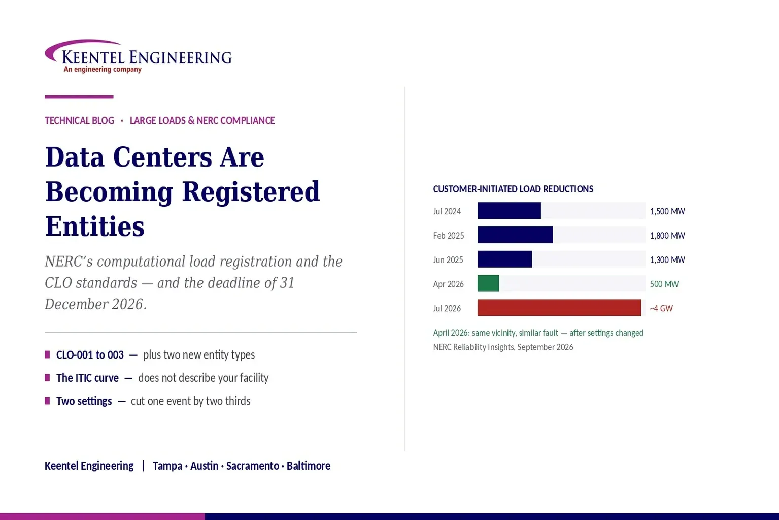
Learn how NERC computational load registration impacts data centers, CLO standards, ride-through requirements, modeling, and grid reliability compliance.
By SANDIP R PATEL
•
September 7, 2026
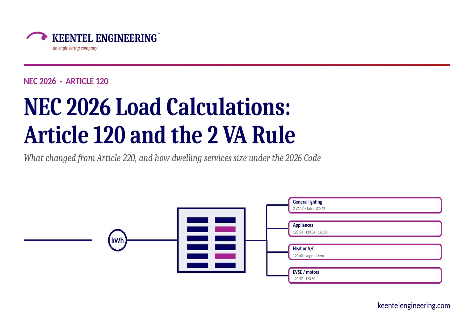
Learn NEC 2026 load calculations, Article 120 changes, the 2 VA rule, EV charging requirements, service sizing, and dwelling calculation methods.

By SANDIP R PATEL
•
September 7, 2026
Learn five essential NEC calculations covering conduit fill, voltage drop, ampacity, motor circuits, and transformer protection with engineering examples.
By SANDIP R PATEL
•
September 7, 2026
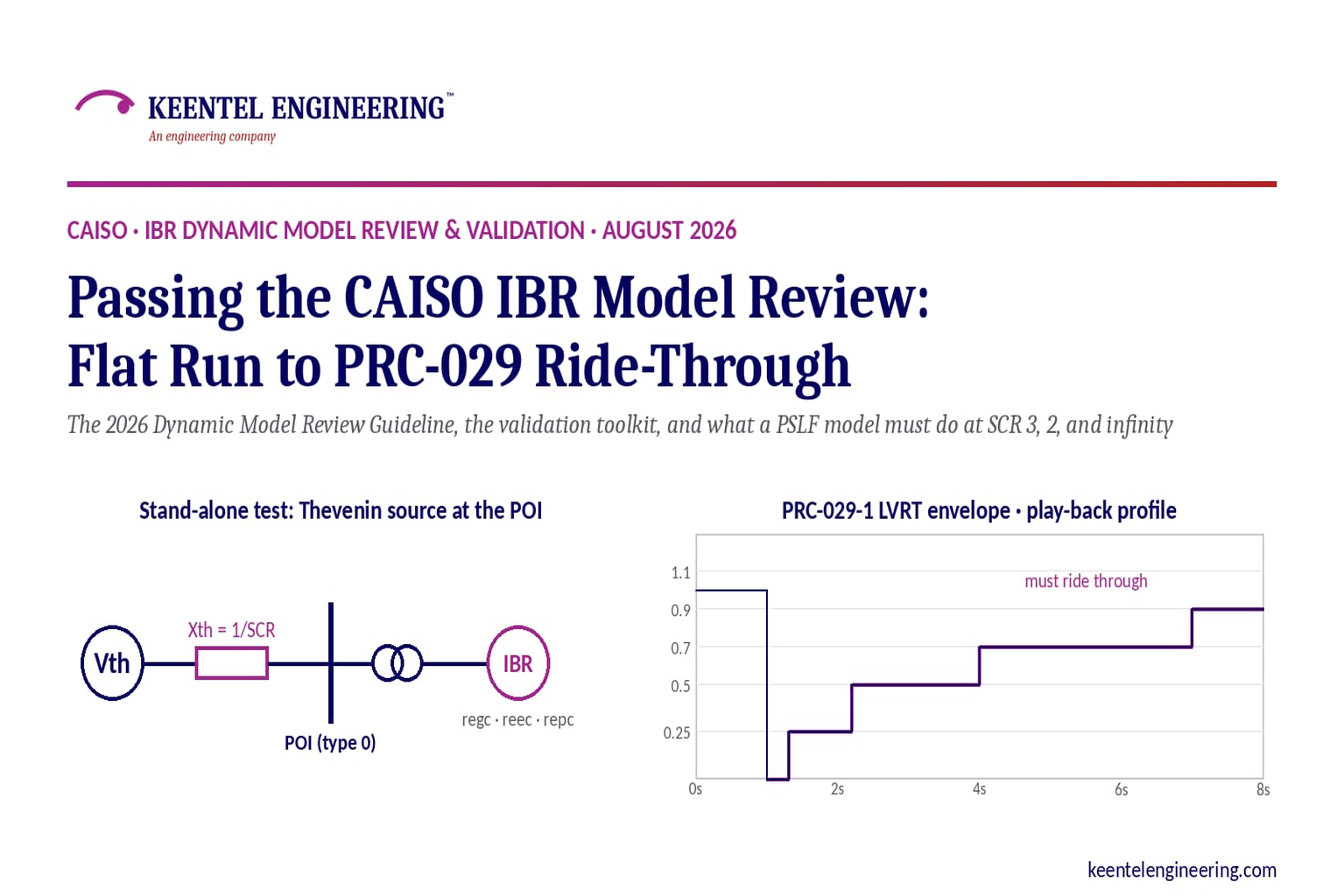
Learn how CAISO reviews IBR models using PSLF validation, PRC-029-1 ride-through requirements, WECC models, and inverter resource compliance testing.

By SANDIP R PATEL
•
September 7, 2026
Understand system earthing and protective earthing, neutral grounding methods, effective grounding, ground grids, and insulation coordination for power systems





