
A Coordinated Electric System Interconnection Review—the utility’s deep-dive on technical and cost impacts of your project.
Challenge: Frequent false tripping using conventional electromechanical relays
Solution: SEL-487E integration with multi-terminal differential protection and dynamic inrush restraint
Result: 90% reduction in false trips, saving over $250,000 in downtime
The three operating regions you have to design to
| Device | Output vs voltage | Response | Best suited to | Main limitations |
|---|---|---|---|---|
| Mechanically switched capacitor or reactor | Proportional to voltage squared | Seconds; discrete steps; limited switching operations per day | Steady-state reactive supply, voltage profile, loss reduction | No dynamic capability; step voltage change on switching; capability collapses when most needed |
| Static var compensator | Capacitive branches proportional to voltage squared | A few cycles; continuously controllable | Continuous control where cost matters and deep voltage support is not the driver | Square-law capability loss; harmonic filters are part of the plant and interact with the network |
| STATCOM | Approximately proportional to voltage — constant current capability | One to two cycles closed loop; converter response faster still | Voltage stability margin, weak interconnections, fast disturbance recovery, flicker and unbalance compensation | Higher capital cost; converter losses; adds a converter and its control dynamics to the network |
| Synchronous condenser | Governed by machine capability and excitation | Excitation response in the hundreds of milliseconds; inherent inertial response instantaneous | System strength and inertia, short-circuit contribution, black start support | Rotating plant with maintenance and losses; slower controlled response than a converter |
| STATCOM with energy storage | Reactive as a STATCOM, plus real power within the storage rating | As STATCOM for reactive; real power limited by storage | Where a real power deficiency is part of the problem | Cost and complexity of the storage; different failure and maintenance profile |
Data Centers Are Becoming Registered Entities
September 9, 2026 | Blog
NERC’s Computational Load Registration and the CLO Standards — the Events That Drove Them, the Gaps They Close, and What a Large Load Owner Has to Do Before the End of 2026
1. Executive Summary
NERC is bringing large computational loads inside the mandatory reliability framework, and the work has to be complete by 31 December 2026. For an owner of a data center or a crypto mining facility, that is not a distant regulatory development — it is a set of engineering obligations arriving next year.
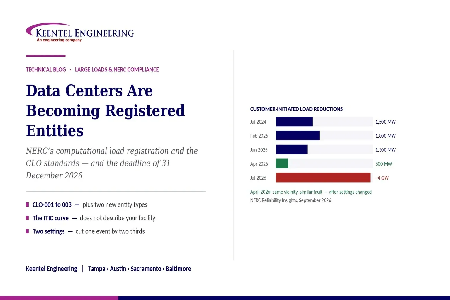
The problem is that large computational loads disconnect from the grid during faults they were never in danger from. A transmission fault clears normally, voltage dips during reclosing, and hundreds or thousands of megawatts of data center demand transfers to backup power and vanishes from the system. NERC has been counting these events. In July 2024 an Eastern Interconnection event removed 1,500 megawatts. In July 2026 a Virginia event removed nearly four gigawatts.
NERC has concluded that the existing Reliability Standards and the processes around them are inadequate for these loads — not because anyone did anything wrong, but because the framework was built when large loads behaved differently. The standards that require generators to ride through disturbances have no equivalent for load. The standards that govern balancing do not treat a large load trip as a contingency event. The standards that require disturbance monitoring do not reach load facilities. The models used to study the system cannot represent what these facilities actually do.
The remedy is running now on two tracks. New registered entity types — Computational Load Owner and Computational Load Operator — with registry criteria that must be finalised by the end of 2026. And three foundational standards, CLO-001 through CLO-003, covering interconnection and modelling data, operational data and communications, and protection coordination and disturbance monitoring. FERC directed both on 16 July 2026.
The most useful finding in all of this is not the regulation. It is the April 2026 data point showing that a fault of the same character in the same vicinity that had removed 1,500 megawatts in 2024 removed only 500 megawatts after the data centers changed their transfer settings. The problem is fixable by engineering, at the facility, without heroic measures. This paper explains what those changes are and why the settings that cause the problem were entirely reasonable when they were made.
The framing an owner should carry into the next twelve months
Your uninterruptible power supply is doing exactly what it was specified to do: protect the load by transferring on a voltage disturbance. That specification was written against equipment protection, not grid reliability.
What is changing is that grid reliability is becoming your obligation too, and the two objectives are in tension at the transfer setting.
2. What aHappened
NERC has been recording these events, and the numbers are what make the regulatory response comprehensible.
| When | Where | What was lost |
|---|---|---|
| July 2024 | Eastern Interconnection | 1,500 MW of data center load |
| February 2025 | Eastern Interconnection | 1,800 MW |
| February 2025 | Eastern Interconnection | 428 MW |
| March 2025 | Eastern Interconnection | 227 MW |
| May 2025 | Eastern Interconnection | 540 MW |
| June 2025 | Eastern Interconnection | 1,300 MW |
| January 2023 to April 2026 | ERCOT — crypto mining | 28 separate loss events, each between 100 and 450 MW |
| January 2023 to April 2026 | ERCOT — crypto mining | 28 separate loss events, each between 100 and 450 MW |
| January 2023 to April 2026 | ERCOT — crypto mining | 28 separate loss events, each between 100 and 450 MW |
Two things stand out. The trajectory is upward — the July 2026 event is more than twice the largest previous one and is described as demonstrating that the risk is increasing rather than abating. And the April 2026 event runs the other way, which is the subject of Section 12.
For scale, NERC’s 2025 Long-Term Reliability Assessment projects aggregate summer peak demand rising by more than 224 gigawatts over its ten-year horizon, at growth levels higher than at any point in the past two decades, with large computational loads a significant driver. The events above happened at the beginning of that build-out.
3. The Mechanism
The events follow a pattern that repeats, and understanding it is the whole of the engineering problem.
- A fault occurs on the transmission system and is cleared normally. Voltage dips at surrounding buses, and dips again as reclosing is attempted to restore the line.
- After several reclosing attempts, the computational load facilities react to the accumulated voltage dips by transferring their load to backup power systems — removing themselves from the grid, to protect their equipment from outage and from damage caused by prolonged low voltage.
- Large amounts of demand disappear from the system at once. Generation that was serving that demand is suddenly in surplus, frequency and voltage rise, and the system oscillates as it rebalances.
Every step in that sequence is equipment behaving as designed. The protection cleared the fault correctly. The reclosing worked as intended. And the facility transfer scheme did precisely what it was specified to do, which is protect a critical load from a voltage disturbance of uncertain duration.
The reason it is a grid problem rather than a facility problem is scale and simultaneity. Because every computational load on a circuit sees the same disturbance and takes the same action, NERC characterises this as a common-mode failure. Geographic concentration compounds it, and Data Center Alley in Virginia is named specifically. A single fault becomes a multi-gigawatt loss because a hundred independent facilities made the same reasonable engineering decision.
There is a second half to the mechanism that receives less attention and is arguably worse. After the load drops, the balancing authority reduces generation to correct the high frequency. The load then ramps back to its pre-disturbance level, and frequency falls because generation has already been re-dispatched downward. NERC notes that this return cannot currently be studied in simulation, because nobody knows when or how fast the load will come back.
4. Why This Is Not Like Losing a Generator
The grid has decades of practice handling the sudden loss of a large generator. Losing a large load is the same magnitude of event with the sign reversed, and the framework does not treat it the same way.
- Generators must ride through. Reliability standards define no-trip zones for voltage and frequency and require generator protection settings to respect them. There is no equivalent requirement for load, and NERC states explicitly that the protection and control standards covering generator settings do not discuss large load performance during voltage and frequency deviations.
- The largest credible generation loss is analysed and feeds the frequency response obligation. Every balancing authority submits its largest credible generator loss, and that figure drives how much frequency response the interconnection must carry. NERC identifies the absence of an equivalent analysis of the largest credible load loss as a gap.
- The disturbance control standard does not include large load tripping in its definition of a balancing contingency event, even though the reliability impact can be equivalent.
- Planning and operations studies do not conventionally assess a contingency that combines a faulted transmission facility with the simultaneous loss of nearby voltage-sensitive load. The scenario that actually occurs is not among the scenarios routinely studied.
There is also an asymmetry in how the system has historically thought about load dropping. Load falling off during a low-frequency event has generally been helpful — it is what underfrequency load shedding does deliberately. What is new is load dropping during a voltage event, at the wrong moment, in quantities nobody planned for, and then returning on its own schedule.
5. The Registration Track
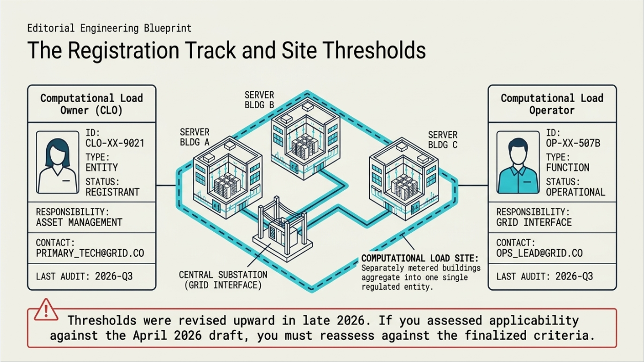
NERC is proposing two new registered entity types: Computational Load Owner and Computational Load Operator. The mechanism is a revision to the Rules of Procedure, principally the compliance registry criteria in Appendix 5B, with related changes to the definitions and the registration manual.
The process to date:
- A draft was posted for a forty-five day comment period beginning 1 April 2026.
- In response to feedback, NERC posted revisions that raised the megawatt and kilovolt thresholds and developed a definition of a Computational Load Site, among other refinements.
- Those revisions went out for a further thirty-day comment period, 19 August to 18 September 2026.
- The registry criteria must be finalised by the end of 2026.
Two observations for an owner. The thresholds moved upward in response to industry comment, which means anyone who assessed applicability against the April draft should reassess against the revised criteria rather than assuming the earlier answer holds. And the introduction of a site definition matters, because it determines how facilities are counted — whether a campus of separately owned or separately metered buildings is one thing or several is exactly the kind of question that decides whether an owner is in or out.
The pattern here should be familiar to anyone who watched the inverter-based resource registration initiative. A population of facilities that had been outside the framework is identified, thresholds are set, and registration follows with the associated standards, evidence and audit exposure. The difference is compression: that initiative ran three years, and this one is being done inside one.
6. The Standards Track: CLO-001, CLO-002, CLO-003
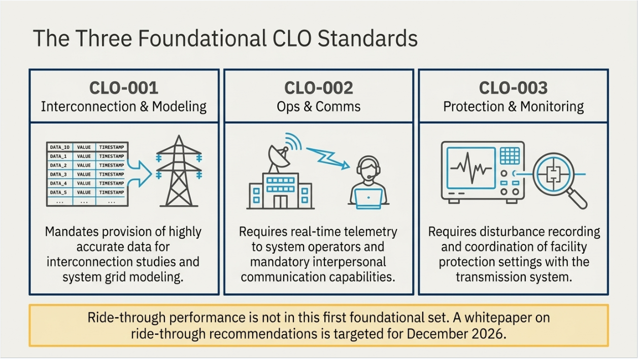
Running concurrently, Project 2026-02 is developing three foundational standards.
| Standard | Subject | What it will reach |
|---|---|---|
| CLO-001-1 | Computational Load Interconnection, Studies, and Modeling Data | The data an owner must provide for interconnection studies and for the models used to plan and operate the system — the modelling gap described in Section 11 |
| CLO-002-1 | Computational Load Operational Data and Communications | Real-time data to system operators and the interpersonal communication capability that generators already have obligations for and loads do not |
| CLO-003-1 | Computational Load Protection Coordination and Disturbance Monitoring | Coordination of facility protection settings with the transmission system, and recording of disturbance data — the two things whose absence makes the current events hard to analyse |
Three points about how these are being written.
- They are derived from requirements in existing enforced standards that have already been compliance-vetted and industry-supported, rather than drafted from nothing. That is a deliberate choice to move quickly, and it means the obligations will look familiar to anyone who has worked with the generator equivalents.
- The proposal also includes limited updates to the facility interconnection requirements and facility interconnection studies standards, which are the standards that govern how a transmission owner sets and applies interconnection requirements.
- Ride-through is not in this first set. NERC is explicit that it will consider additional standards covering ride-through, modelling requirements, and cyber and physical security including supply chain. A white paper on large load disturbance performance and ride-through recommendations is targeted for December 2026, with a Standard Authorization Request under development. So the requirement that most directly addresses the events in Section 2 is the next wave, not this one.
The initial comment period ran 19 August to 18 September 2026, with balloting in the final ten days, and the ballot pool closed on 3 September 2026.
7. The Deadline
On 16 July 2026 FERC directed NERC to develop and submit new or modified Reliability Standards and registry criteria by 31 December 2026 to address the reliability risks associated with integrating computational loads into the bulk power system.
That is a short timeline by the standards of this process, and it explains several features of the programme that would otherwise look rushed — the derivation of the standards from already-vetted requirements, the concurrent rather than sequential tracks, the compressed comment periods, and the decision to start with foundational data and communications obligations and address performance requirements afterwards.
It also means the practical dates for an owner are close. Registry criteria final by year end. Standards submitted by year end. Then FERC review, approval, and effective dates that will follow within a period measured in months rather than years, given the posture of the directive.
The planning assumption worth making
An owner of a large computational load should plan on the basis that registration determination arrives in 2027 and that obligations attach shortly after.
The engineering that satisfies those obligations — models, monitoring, protection coordination, operational data paths — has lead time. Beginning it after the criteria are final leaves very little room.
8. The Gap Inventory
The most useful part of NERC’s analysis for an engineer is the inventory of which standards do not reach large loads, and why. The following is a condensed version.
| Area | What is missing | Consequence |
|---|---|---|
| Ride-through performance | The generator protection setting and ride-through standards do not address large load performance during voltage or frequency deviations. There is no defined no-trip zone for load | Responses vary widely between facilities and cannot be predicted, so the event in Section 4 cannot be planned for |
| Disturbance monitoring | The disturbance monitoring standard lacks data requirements for large loads | Planners and operators cannot evaluate ride-through performance after an event because the recordings do not exist |
| Balancing contingency definition | Large load tripping and ramping are not within the balancing contingency event definition | A load loss with equivalent reliability impact to a generation loss is not treated as a contingency |
| Largest credible load loss | No recurring analysis, in contrast to the largest credible generation loss that drives the frequency response obligation | The interconnection’s frequency response requirement is not informed by the load-loss risk |
| Communications | Large loads are not obligated to establish interpersonal communication capability with system operators, unlike generators | Miscommunication during emergencies, and no defined path for operating instructions |
| Outage coordination | The outage coordination standard covers transmission and generation outages, not large load outages | A large load coming out of or into service is not coordinated the way an equivalent generator would be |
| Ramping | No specific guidance or constraint on how quickly large loads may ramp | Area control error and frequency excursions from ramping that no requirement addresses |
| Planning studies | Planning and operations planning standards do not consider large-scale ramping, disconnection and reconnection events | The studies do not evaluate the scenario that actually occurs |
| Interconnection | No standardisation of load interconnection studies or performance requirements; limited data sharing and coordination | Every transmission owner solves it differently, and the load owner faces different requirements in each territory |
| Modelling | The composite load model’s electronic load component cannot represent modern rectifier-driven facilities; model availability, information, guidance and validation all identified as gaps | Studies cannot represent the behaviour that causes the events — see Section 11 |
9. The ITIC Curve Problem
One finding deserves separate treatment because it corrects an assumption that is widely relied on and is wrong in a specific and consequential way.
Reliability coordinators, balancing authorities and transmission operators have used the information technology industry voltage tolerance curve to estimate when large electronic loads will reduce consumption or transfer to backup supply. It is the natural reference: it is well known, it describes the voltage tolerance of information technology equipment, and it appears to answer the question.
NERC points out that it does not. The curve applies to power supplies. In a data center there is an uninterruptible power supply between the grid and those power supplies, and it is the transfer settings of that system — together with any other site-level protection — that determine what the facility does during a voltage disturbance. The curve describes the tolerance of equipment that is not the equipment making the decision.
The consequence is that ride-through characteristics vary significantly between facilities, in ways that cannot be inferred from the technology at all. Two data centers with identical servers and different transfer settings behave completely differently during the same disturbance. And because the settings are not currently required to be disclosed, verified or modelled, the system operator has no way to know which one is on their system.
This is the technical heart of the whole matter. The behaviour that causes multi-gigawatt events is a configurable setting in a piece of facility equipment, and at present nobody outside the facility knows what it is set to.
10. What Ride-Through Means for a Data Center
For an owner wondering what is actually being asked, it is worth looking at what the facilities that improved their performance actually changed.
They adjusted the protection and control schemes that determine when the facility transfers to backup supply. Specifically, they lengthened the time duration a voltage dip must persist before it is counted, and they altered the number of depressions within a defined period that would trigger disconnection.
Both changes are worth understanding because they address the two ways the mechanism actually bites.
- Duration. A short dip from a fault that clears in a few cycles is not a threat to the load. A transfer scheme that counts it as one is transferring for an event that would have passed. Lengthening the qualifying duration means the facility rides through the ordinary case.
- Count. The pattern in Section 4 is not one dip — it is several, from reclosing attempts. A scheme that counts depressions within a window and transfers on the third will transfer during normal reclosing even if no individual dip qualifies. Adjusting that logic is what stops normal system restoration from looking like a sustained problem.
Two qualifications belong with this. Any such change must be made with the equipment vendor and against the actual tolerance of the load being protected — this is an engineering change to a protection scheme, not a parameter to be relaxed until the alarms stop. And it involves a genuine trade: a facility that rides through longer is exposed to the disturbance for longer. That trade is the owner’s to make, informed by what the equipment actually tolerates rather than by the conservative default.
The transmission entity involved then included these requirements for all newly connected facilities. Interconnection requirements are already moving ahead of the standards, and several system operators and utilities are developing large load ride-through requirements of their own. An owner may face a requirement from their interconnecting utility before any NERC standard is effective.
11. The Modeling Gap
The modelling position is the part most directly relevant to engineering practice, and it is uncomfortable: the models used to study these systems cannot represent the behaviour that causes the events.
The composite load model used by most utilities was developed for a load population dominated by single-phase residential air conditioning, with an electronic load component sized for consumer electronics. NERC states plainly that this component is insufficient for modern large loads, which are dominated by power electronic rectifier systems with sophisticated controls whose ride-through behaviour cannot be represented by it.
Work is under way. A positive-sequence model for aggregated vehicle chargers has been used as a proxy for data center disconnection studies. A newer model for large power-electronic loads represents the current state of the art and reduces some of the identified gaps. The gaps that remain are instructive.
- Rectifier dynamics are represented by simple first-order transfer functions, on an assumption of stable control and slow dynamics, and that simplification has not been tested against the range of large rectifier equipment actually installed.
- The control logic was designed to replicate observed vehicle charger behaviour and may not represent uninterruptible power supplies or other equipment. It is not yet clear whether one model suffices or several are needed.
- Cyclic load injection — the characteristic pattern of artificial intelligence training workloads — is a behaviour the models were not built for.
There are also gaps in electromagnetic transient model availability, in the information available to build models, in guidance and practice for modelling these facilities, and in validation and model quality testing. That last one is the same problem the inverter-based world has spent several years on: a model that has not been validated against the equipment as configured is a description of something else.
For an owner, the practical consequence is that CLO-001 will require modelling data, and the models that data feeds are themselves still maturing. Being early and being accurate is worth more here than being compliant late, because the model of a facility is what determines how that facility is represented in every study the system operator runs.
12. What the April 2026 Event Proved
The single most important finding in the whole of this work is a comparison between two events.
On 18 April 2026 a transmission fault occurred in the same vicinity, with similar characteristics, as a July 2024 event that had caused 1,500 megawatts of load loss. The April 2026 event produced 500 megawatts of sustained data center load loss. NERC attributes the improvement to the changes the data centers made, and describes it as demonstrating that collaboration can mitigate the risk.
That is a two-thirds reduction, on the same system, from the same class of event, achieved by adjusting settings in facility equipment. It establishes three things.
- The problem is fixable by engineering at the facility, without new grid infrastructure and without compromising the protection of the load.
- The behaviour is a configuration, not a property of data centers. Nothing physical changed between 2024 and 2026 except the settings.
- An owner who does this work voluntarily is doing something demonstrably effective rather than performing compliance. That is a materially better position to be in when the standards arrive, and a better story to tell an interconnecting utility during a study process.
Set against it, the July 2026 Virginia event of nearly four gigawatts, still under analysis and described as evidence that the risk is increasing rather than abating. Both things are true: the mitigation works, and it has not been applied widely or quickly enough to keep pace with the build-out.
13. What an Owner Should Do Now
The following is what a large computational load owner should have under way before the registry criteria are finalised.
- Assess applicability against the revised criteria, not the April draft. The thresholds were raised and a site definition introduced. If an earlier assessment concluded the facility was outside the criteria, that conclusion needs rechecking — particularly for campuses where how a site is defined determines how capacity aggregates.
- Find out what your transfer settings actually are. The qualifying dip duration, the depression count and window, and any other site-level protection that can initiate a transfer. This is a documented fact about the facility that surprisingly few owners can state, and every subsequent step depends on it.
- Establish what the load actually tolerates, as distinct from what the transfer scheme assumes. The margin between the two is where ride-through improvement comes from, and it is an equipment and vendor question rather than a grid question.
- Evaluate the two adjustments the improved facilities made — qualifying duration and depression count — with the equipment vendor, against the actual tolerance, as a protection change rather than a parameter relaxation.
- Verify what disturbance recording exists. If the facility cannot produce a record of what its voltage did and what its protection did during an event, it cannot demonstrate performance, contest an attribution, or improve on evidence. CLO-003 points directly at this.
- Establish the modelling data position. What data exists, in what format, and whether the facility can be represented in the models the transmission planner uses. CLO-001 will require this and the underlying models are still maturing.
- Confirm the operational communication path. Who at the facility can receive an operating instruction from the system operator, on what medium, verified how. Generators have obligations here and loads currently do not, which is one of the gaps NERC has named.
- Check the interconnecting utility’s requirements now, separately from the NERC track. Utilities and system operators are developing their own large load ride-through requirements, and a requirement in an interconnection agreement binds regardless of what NERC has finalised.
- Assign ownership. Registration brings evidence, retention and audit exposure to organisations that have never had them. Someone has to own that, and the inverter-based experience is that the organisations which appointed someone early fared considerably better.
14. Points That Are Commonly Misread
The events are not equipment failures
Every element in the sequence performed as designed — the protection, the reclosing, and the facility transfer scheme. What makes it a reliability problem is that many facilities make the same reasonable decision simultaneously, which NERC identifies as a common-mode failure.
Ride-through is not in the first standards set
CLO-001 through CLO-003 cover interconnection and modelling data, operational data and communications, and protection coordination and disturbance monitoring. Ride-through performance requirements are signalled for a later wave, with a white paper targeted for December 2026. An owner who reads the CLO set and concludes that ride-through is not coming has misread the sequence.
The ITIC curve does not describe your facility
It applies to power supplies. In a data center the uninterruptible power supply sits between the grid and those power supplies, and its transfer settings determine the facility’s behaviour. Ride-through varies enormously between sites with identical equipment.
The registration thresholds moved
The criteria posted in April were revised upward in megawatt and kilovolt terms, and a site definition was added. Any applicability assessment based on the earlier draft should be redone.
The reliability guideline is voluntary; the standards will not be
The May 2026 guideline supplements rather than replaces standards and is explicitly non-binding. It is a good statement of practice and it is not the obligation. The obligation is the CLO standards and the registry criteria.
The most important finding is the good news
A two-thirds reduction in load loss on the same system from the same class of fault, achieved by changing settings. The regulatory programme exists because the problem is real; the April 2026 result exists because it is solvable.
15. Keentel Services for Large Load Projects
Keentel Engineering works on both sides of this boundary — the facility engineering that determines how a large load behaves during a disturbance, and the interconnection and compliance engineering that demonstrates it.
15.1 Ride-Through and Facility Performance
- Assessment of existing transfer and protection schemes — qualifying dip duration, depression count and window, and any other site-level initiation — documented as a stated facility characteristic rather than an unexamined default.
- Determination of actual load tolerance against transfer scheme assumptions, with the equipment vendors, to establish the available ride-through margin.
- Evaluation and specification of protection and control changes to improve ride-through, treated as an engineered protection change with the load exposure trade made explicitly.
- Voltage sag study of the site’s disturbance environment — expected depth, duration and frequency from the connecting system — so that settings are chosen against the actual exposure rather than a generic assumption.
- Coordination of facility protection with the transmission system, including reclosing practice on the connecting circuits, which is the interaction that drives the multiple-dip pattern.
15.2 Modelling, Monitoring, and Data
- Modelling data preparation and facility representation for interconnection and planning studies, including positive-sequence and electromagnetic transient representation where required.
- Disturbance monitoring architecture — what is recorded, at what resolution, retained how long, and retrievable by whom — designed against what CLO-003 and NERC’s analysis identify as needed rather than what the building management system happens to capture.
- Operational data and communication path design between the facility and the system operator, including verification.
- Event analysis and post-disturbance performance assessment where a facility has reduced load and the cause or attribution is in question.
15.3 Interconnection and Compliance
- Large load interconnection engineering, application support and study-phase technical packages, and coordination with the utility, transmission provider and system operator.
- Registration applicability assessment against the current registry criteria, including how a site definition applies to campus and phased developments.
- Compliance programme development for newly registered entities — obligation register, ownership assignment, evidence design and review cycle — sized to organisations that have not previously been registered.
- Review of utility and system operator large load requirements as they emerge, which are moving ahead of the standards in several territories.
15.4 Campus Electrical Engineering
- Point-of-interconnection and substation design, campus medium-voltage distribution, on-site generation and storage integration, and backup power architecture.
- Load flow, short-circuit, protective coordination, arc-flash, motor starting, harmonic and power quality studies, including distortion compliance assessed at the correct point.
- Owner’s engineer services, design review of EPC and vendor packages, and QA/QC of third-party studies and models.
Keentel Engineering holds a Florida Certificate of Authorization and maintains offices in Tampa, Austin, Sacramento, and Baltimore, supporting projects across the interconnections.
16. References and Further Reading
This paper is based on the three NERC publications listed first. NERC materials are updated frequently and this programme is moving quickly; check for later versions before relying on any date or threshold.
Primary Sources
- Assessment of Gaps in Existing Practices, Requirements, and Reliability Standards for Emerging Large Loads — NERC Large Loads Working Group white paper, March 2026 — North American Electric Reliability Corporation
- Large Loads Frequently Asked Questions, August 2026 — North American Electric Reliability Corporation
- Reliability Insights: Large Computational Load Risks Due to Voltage Sensitivity, September 2026
— issued by NERC with MRO, NPCC, ReliabilityFirst, SERC, Texas RE and WECC — North American Electric Reliability Corporation and the Regional Entities
Related NERC Material
- Characteristics and Risks of Emerging Large Loads — Large Loads Task Force white paper, July 2025, and the Large Loads Action Plan — North American Electric Reliability Corporation
- Reliability Guideline: Risk Mitigation for Emerging Large Loads, May 2026 — voluntary and non-binding — North American Electric Reliability Corporation
- Level 2 Industry Recommendation Alert on large load interconnection, study, commissioning and operations, September 2025, and the Level 3 Essential Action Alert of May 2026 — North American Electric Reliability Corporation
- Project 2026-02 — the computational load standards development project, including the proposed CLO-001-1, CLO-002-1 and CLO-003-1, and the proposed changes to the Rules of Procedure registry criteria — North American Electric Reliability Corporation
- 2025 Long-Term Reliability Assessment, source of the demand growth projection cited in this paper — North American Electric Reliability Corporation
Standards and Technical References
- NERC Reliability Standards — including the PRC series covering protection settings, ride-through and disturbance monitoring, the BAL series covering balancing and frequency response, the TOP and IRO series covering operations and outage coordination, the TPL and FAC series covering planning and interconnection, and the COM and PER series covering communications — North American Electric Reliability Corporation
- IEEE Std 1668, Recommended Practice for Voltage Sag and Short Interruption Ride-Through Testing for End-Use Electrical Equipment Rated Less than 1,000 V — IEEE Standards Association
- IEEE Std 519 for harmonic control, IEEE Std 2800 for transmission-connected inverter-based resources, and IEEE Std 1547 for distributed energy resources — IEEE Standards Association
- IEEE Std 1159 for power quality monitoring, and the information technology industry voltage tolerance curve discussed in Section 10 — IEEE Standards Association and Information Technology Industry Council
https://standards.ieee.org/
17. Frequently Asked Questions
Q1. What is actually happening to data centers under NERC?
Two things concurrently. New registered entity types — Computational Load Owner and Computational Load Operator — with registry criteria that must be finalised by the end of 2026. And three foundational Reliability Standards, CLO-001 through CLO-003. FERC directed both on 16 July 2026 with a 31 December 2026 deadline.
Q2. Why is NERC doing this now?
Because large computational loads have repeatedly disconnected from the grid during faults that were cleared normally, removing hundreds to thousands of megawatts of demand at once. NERC concluded in March 2026 that the existing standards and processes are inadequate to address the risk.
Q3. How large have the events been?
NERC records Eastern Interconnection data center load reductions of 1,500 MW in July 2024, 1,800 MW and 428 MW in February 2025, 227 MW in March 2025, 540 MW in May 2025 and 1,300 MW in June 2025, plus 28 crypto mining events in ERCOT between January 2023 and April 2026 at 100 to 450 MW each. In July 2026 a Virginia event removed nearly 4 GW.
Q4. What causes the disconnection?
A fault clears normally and voltage dips, then dips again during reclosing. After several dips the facility transfers its load to backup power to protect equipment from a disturbance of uncertain duration. The demand disappears from the system, and generation that was serving it is suddenly in surplus.
Q5. Is that an equipment failure?
No. Every element performed as designed — the protection cleared the fault, the reclosing worked, and the transfer scheme protected the load exactly as specified. It becomes a reliability problem because many facilities on the same circuit see the same disturbance and take the same action, which NERC identifies as a common-mode failure.
Q6. Why is this treated differently from losing a generator?
Because the framework already handles generation loss and does not handle load loss. Generators have enforceable ride-through requirements and no-trip zones; loads have none. The largest credible generation loss is analysed and drives the frequency response obligation; there is no equivalent load analysis. And large load tripping is not within the balancing contingency event definition.
Q7. What do CLO-001, CLO-002 and CLO-003 cover?
CLO-001 covers interconnection, studies and modelling data. CLO-002 covers operational data and communications. CLO-003 covers protection coordination and disturbance monitoring. They are derived from requirements in existing enforced standards that have already been compliance-vetted.
Q8. Does the first standards set include ride-through requirements?
No, and this is easy to misread. The first set is foundational — data, communications, protection coordination and monitoring. NERC has signalled that ride-through, modelling requirements and security protections will follow, with a white paper on large load disturbance performance and ride-through recommendations targeted for December 2026.
Q9. What are the registration thresholds?
They are still being finalised. What matters is that the criteria posted for comment in April 2026 were revised upward in both megawatt and kilovolt terms, and a Computational Load Site definition was added. Any applicability assessment based on the April draft needs redoing.
Q10. Why does the site definition matter?
Because it determines how facilities are counted. Whether a campus of separately metered or separately owned buildings is one site or several decides how capacity aggregates against the threshold, and therefore whether an owner is inside the criteria at all.
Q11. What is the deadline?
FERC directed NERC to develop and submit new or modified Reliability Standards and registry criteria by 31 December 2026. Registration determinations and effective dates follow after that, and a sensible planning assumption is that obligations attach during 2027.
Q12. What is the ITIC curve problem?
System operators have used the information technology voltage tolerance curve to estimate when large electronic loads will drop. NERC points out it applies to power supplies — but in a data center the uninterruptible power supply sits between the grid and those supplies, and its transfer settings determine the behaviour. The curve describes equipment that is not making the decision.
Q13. So how much do facilities vary?
Enormously, and unpredictably from the outside. Two data centers with identical servers and different transfer settings behave completely differently during the same disturbance, and because the settings are not currently required to be disclosed or verified, the system operator cannot know which is on their system.
Q14. What did the facilities that improved actually change?
Two things. They lengthened the time a voltage dip must persist before it is counted, so short dips from normally cleared faults no longer qualify. And they altered the number of depressions within a defined period that would trigger disconnection, so normal reclosing no longer looks like a sustained problem.
Q15. How much difference did it make?
On 18 April 2026 a fault of similar character in the same vicinity as a July 2024 event that had caused 1,500 MW of loss produced only 500 MW of sustained loss. A two-thirds reduction, on the same system, achieved by changing settings in facility equipment.
Q16. Is there a downside to riding through longer?
Yes, and it is a real trade. A facility that rides through longer is exposed to the disturbance for longer. The change must be made with the equipment vendor against what the load actually tolerates — it is an engineered protection change, not a parameter to relax until the alarms stop.
Q17. Should I wait for the standards before doing anything?
No, for two reasons. The engineering has lead time and the dates are close. And utilities and system operators are developing their own large load ride-through requirements independently — the transmission entity in the April 2026 case applied its new requirements to all newly connected facilities. An interconnection agreement binds regardless of what NERC has finalised.
Q18. What is wrong with the models used to study these facilities?
The composite load model most utilities use was built for a load population dominated by residential air conditioning, with an electronic load component sized for consumer electronics. NERC states it is insufficient for modern large loads dominated by rectifier systems with sophisticated controls, whose ride-through cannot be represented by it.
Q19. Is that being fixed?
Work is under way. A vehicle charger model has been used as a proxy, and NERC notes a newer model for large power-electronic loads represents the current state of the art and reduces some gaps. Remaining concerns include whether simplified rectifier dynamics hold across the range of installed equipment, whether one model suffices, and how to represent the cyclic load pattern of AI training workloads.
Q20. What should I do about modelling?
Establish what data exists and in what format, and get the facility represented accurately early. CLO-001 will require modelling data, the underlying models are still maturing, and the model of your facility is what determines how it appears in every study the system operator runs.
Q21. What is the disturbance monitoring obligation likely to require?
CLO-003 covers protection coordination and disturbance monitoring, and NERC identifies the absence of large load data monitoring requirements as a gap that prevents planners from evaluating ride-through performance. Practically: recording of what voltage did and what the facility protection did, at adequate resolution, retained and retrievable.
Q22. Why does communication appear in this?
Because generators have obligations to establish interpersonal communication capability with system operators and to receive operating instructions, and large loads do not. NERC identifies that as a gap that can worsen emergencies. CLO-002 addresses it.
Q23. Does the May 2026 reliability guideline impose obligations?
No. It supplements rather than replaces standards and is explicitly voluntary and non-binding. It is a useful statement of practice on modelling, analysis, coordination, data collection, monitoring and event analysis — but the obligations are the registry criteria and the CLO standards.
Q24. How does this compare to the inverter-based resource registration?
Structurally very similar — a population outside the framework is identified, thresholds are set, registration follows with standards and audit exposure. The difference is compression. That initiative ran three years; this one is being done inside one, under a FERC deadline.
Q25. If I do one thing this quarter, what should it be?
Find out what your transfer settings actually are — the qualifying dip duration, the depression count and the window. It is a documented fact about your facility that remarkably few owners can state, every subsequent step depends on it, and it is the setting that determines whether your site contributes to the next multi-gigawatt event.
Notice and Disclaimer
This document is original technical content prepared by Keentel Engineering LLC for general professional information. It is not legal, regulatory, or project-specific engineering advice, and it does not constitute a registration determination, an applicability determination, a compliance determination, or a design for any facility.
Facts about events, dates, standards, thresholds and programme status are taken from the three NERC publications identified in the References section, as published. This programme is moving quickly under a regulatory deadline: registry criteria, standard content, comment periods and effective dates are subject to change, and several matters described here were expressly stated by NERC as not yet final. Verify the current position with NERC, the applicable Regional Entity and the interconnecting utility before making any decision.
Analysis, inference, engineering commentary and the recommended actions in this document are Keentel Engineering’s own assessment and should not be attributed to NERC, any Regional Entity, any regulator, or any party named or referenced.
Descriptions of facility protection and transfer scheme behaviour are general engineering discussion; any change to a protection or control scheme must be made by qualified persons with the equipment manufacturer and against the actual tolerance of the equipment being protected.
Keentel Engineering LLC is an independent engineering consultancy. Reference to any regulator, reliability organisation, regional entity, standard, industry organisation, utility, or facility in this document does not imply affiliation with, endorsement by, or sponsorship from any such organisation.

About the Author:
Sandip "Sonny" R. Patel, P.E.
IEEE Senior Member · Founder & CEO, Keentel Engineering
In 1995, Sonny Patel earned his Electrical Engineering degree from the University of Illinois. But degrees don't build legacies — action does.
For three decades, he has worked the power industry from every side of the table: 16 years as a utility engineer at Exelon/Commonwealth Edison; generation leadership across hydroelectric, industrial steam turbine, and a 9 GW renewable fleet; NERC Regional Entity Senior Compliance Engineer and Audit Team Lead, auditing some of the nation's largest utilities; and testing and commissioning lead on equipment up to 765 kV — the very top of the North American grid.Utility. Generator. Regulator. Consultant. Few engineers have seen all four seats. Fewer still have sat in them.
His experience spans nuclear, hydro, conventional generation, renewables, oil and gas, mining — and today's data centers, where he is authoring a three-book series on data center design. He is a Licensed Professional Engineer in six states and a Licensed Electrical Contractor in Florida (Unlimited EC) — he doesn't just design the work; he's qualified to stand behind its execution.Today, as Founder and CEO of Keentel Engineering, Sonny leads a nationwide team of engineers delivering substation design, power system studies, NERC compliance, and commissioning — done right, coast to coast.Three decades. Every side of the table. One standard: accountable engineering.
Services

Let's Discuss Your Project
Let's book a call to discuss your electrical engineering project that we can help you with.
About the Author:
Sandip "Sonny" R. Patel, P.E.
IEEE Senior Member · Founder & CEO, Keentel Engineering
In 1995, Sonny Patel earned his Electrical Engineering degree from the University of Illinois. But degrees don't build legacies — action does.
For three decades, he has worked the power industry from every side of the table: 16 years as a utility engineer at Exelon/Commonwealth Edison; generation leadership across hydroelectric, industrial steam turbine, and a 9 GW renewable fleet; NERC Regional Entity Senior Compliance Engineer and Audit Team Lead, auditing some of the nation's largest utilities; and testing and commissioning lead on equipment up to 765 kV — the very top of the North American grid.
Utility. Generator. Regulator. Consultant. Few engineers have seen all four seats. Fewer still have sat in them.
His experience spans nuclear, hydro, conventional generation, renewables, oil and gas, mining — and today's data centers, where he is authoring a three-book series on data center design. He is a Licensed Professional Engineer in six states and a Licensed Electrical Contractor in Florida (Unlimited EC) — he doesn't just design the work; he's qualified to stand behind its execution.
Today, as Founder and CEO of Keentel Engineering, Sonny leads a nationwide team of engineers delivering substation design, power system studies, NERC compliance, and commissioning — done right, coast to coast.Three decades. Every side of the table. One standard: accountable engineering.
Leave a Comment
Thank you for contacting us.
We will get back to you as soon as possible.
We will get back to you as soon as possible.
Oops, there was an error sending your message.
Please try again later.
Please try again later.
Related Posts
By SANDIP R PATEL
•
October 23, 2026
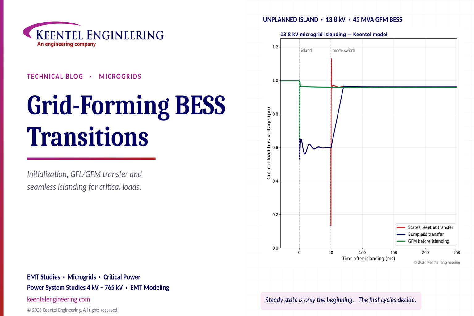
Explore grid-forming BESS initialization, GFL-to-GFM transitions, seamless islanding, EMT simulations, current limiting and microgrid protection.
By SANDIP R PATEL
•
October 23, 2026
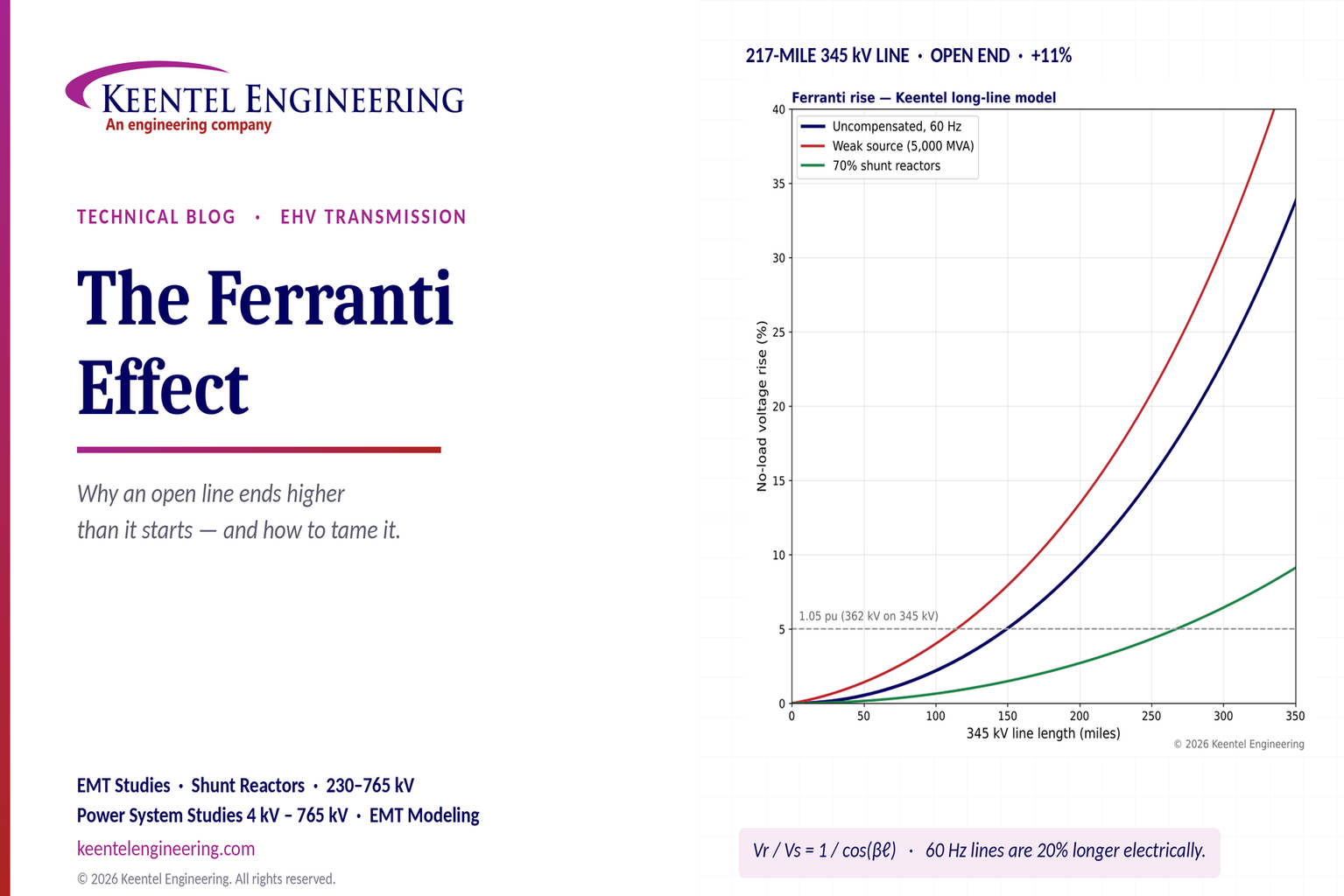
Explore the Ferranti effect in EHV transmission lines: voltage rise, 345 kV examples, switching overvoltages, shunt reactor sizing and mitigation.
By SANDIP R PATEL
•
October 23, 2026
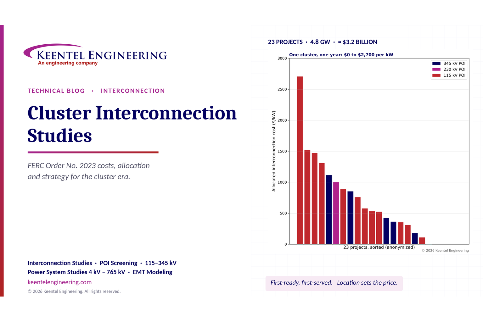
Explore cluster interconnection studies under FERC Order 2023, including network upgrades, cost allocation, withdrawal penalties and developer strategy.
By SANDIP R PATEL
•
October 21, 2026
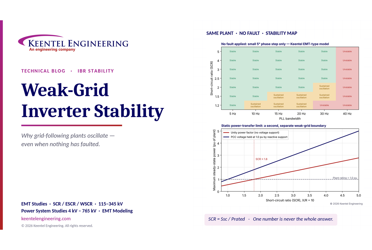
Learn why grid-following inverters become unstable without grid faults. Explore SCR, PLL interactions, EMT studies, grid strength, and mitigation.
By SANDIP R PATEL
•
October 21, 2026
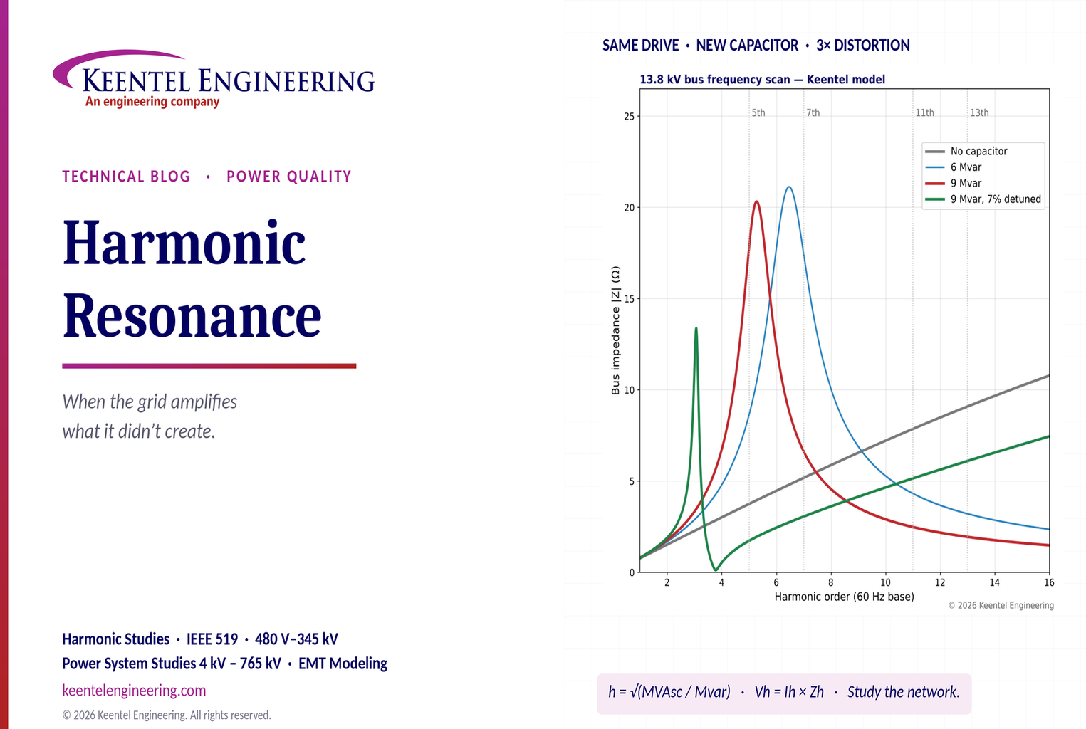
Learn how harmonic resonance amplifies distortion in power systems. Explore capacitor banks, detuned reactors, frequency scans, and IEEE 519 solutions.
By SANDIP R PATEL
•
October 20, 2026
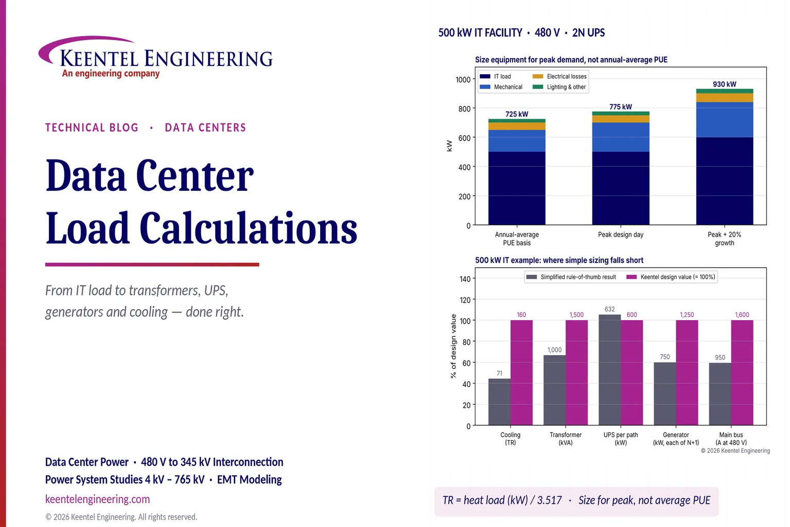
Learn data center electrical load calculations, including IT demand, PUE, UPS and generator sizing, cooling loads, redundancy, and worked US examples.
By SANDIP R PATEL
•
October 20, 2026
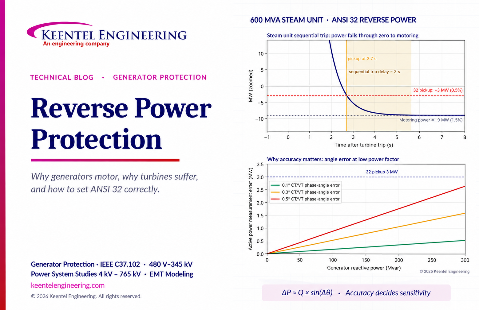
Learn reverse power protection (ANSI 32), generator motoring, relay pickup settings, time delays, sequential tripping and testing for US power plants.

By Team 2 Dexora
•
October 20, 2026
Explore grounding system testing with Keentel Engineering. Learn IEEE 80/81 methods, soil resistivity, ground resistance, and touch and step voltage safety.

By SANDIP R PATEL
•
October 13, 2026
Plan data center capacity with land screening, MW-per-acre estimates, grid power availability and interconnection feasibility studies from Keentel Engineering.





