
A Coordinated Electric System Interconnection Review—the utility’s deep-dive on technical and cost impacts of your project.
Challenge: Frequent false tripping using conventional electromechanical relays
Solution: SEL-487E integration with multi-terminal differential protection and dynamic inrush restraint
Result: 90% reduction in false trips, saving over $250,000 in downtime
The three operating regions you have to design to
| Device | Output vs voltage | Response | Best suited to | Main limitations |
|---|---|---|---|---|
| Mechanically switched capacitor or reactor | Proportional to voltage squared | Seconds; discrete steps; limited switching operations per day | Steady-state reactive supply, voltage profile, loss reduction | No dynamic capability; step voltage change on switching; capability collapses when most needed |
| Static var compensator | Capacitive branches proportional to voltage squared | A few cycles; continuously controllable | Continuous control where cost matters and deep voltage support is not the driver | Square-law capability loss; harmonic filters are part of the plant and interact with the network |
| STATCOM | Approximately proportional to voltage — constant current capability | One to two cycles closed loop; converter response faster still | Voltage stability margin, weak interconnections, fast disturbance recovery, flicker and unbalance compensation | Higher capital cost; converter losses; adds a converter and its control dynamics to the network |
| Synchronous condenser | Governed by machine capability and excitation | Excitation response in the hundreds of milliseconds; inherent inertial response instantaneous | System strength and inertia, short-circuit contribution, black start support | Rotating plant with maintenance and losses; slower controlled response than a converter |
| STATCOM with energy storage | Reactive as a STATCOM, plus real power within the storage rating | As STATCOM for reactive; real power limited by storage | Where a real power deficiency is part of the problem | Cost and complexity of the storage; different failure and maintenance profile |
PJM Now Wants a PSCAD Model. Here Is What That Actually Involves
September 6, 2026 | Blog
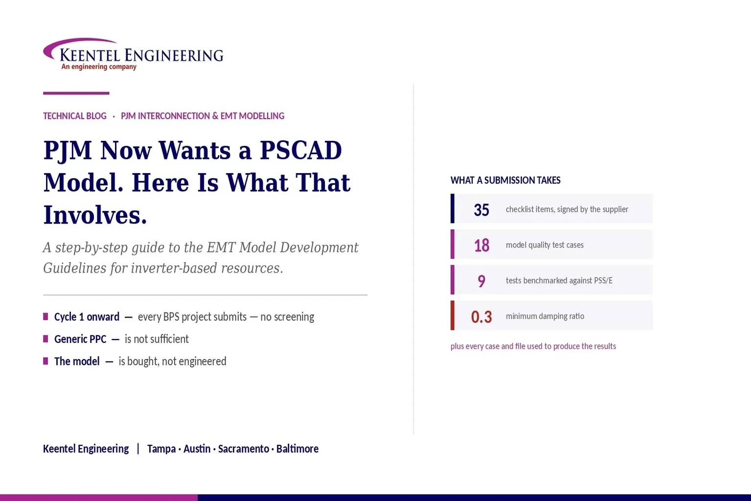
A Step-by-Step Guide to the PJM EMT Model Development Guidelines for Inverter-Based Resources — the Thirty-Five Item Checklist, the Eighteen Test Cases, the PSS/E Benchmark, and Where Submissions Fail
1. Executive Summary
PJM issued Revision 0 of its EMT Model Development Guidelines for Inverter-Based Resources on 5 March 2026. It sets out what an electromagnetic transient model of a solar, storage, wind or hybrid plant must contain, how it must be tested, how it must be benchmarked against the positive-sequence model, and what a complete submission looks like.
The document is short on prose and long on specifics: a thirty-five item model requirements checklist that the model supplier must sign, eighteen model quality test cases with defined operating points and acceptance criteria, a cross-platform benchmark against the PSS/E model, and a deliverables list that includes every case and file used to produce the results so that PJM can rerun them.
Two things about it deserve to be understood before anyone starts work. The first is that PJM states its purpose plainly: to surface deficiencies and conflicts between the PSS/E and EMT models before the data package is submitted and studies begin, so that study delays are minimised. This is a front-loading exercise. The work moves earlier in the schedule; it does not disappear.
The second is that most of the requirements cannot be satisfied by the developer. Real hardware control code, detailed inner control loops, full switching representation, actual protection code, and a plant controller that matches the equipment as configured all come from the inverter manufacturer and the plant controller supplier. If the right model and the right rights to use it were not secured at procurement, no amount of engineering effort later will produce a compliant submission.
This paper works through the scope, the timeline, what the model must contain, the checklist, all eighteen tests, the benchmark requirements, the deliverables, a step-by-step process, and the places where submissions fail.
The sentence to take to procurement
A PJM-compliant PSCAD model is a purchased item, not an engineered one. What engineering can do is assemble it, test it, benchmark it and defend it.
Model availability, real-code content, documentation, version identification and the right to share with PJM belong in the equipment purchase specification with delivery dates tied to project milestones.
2. Why PJM Issued This
The reasoning in the introduction is worth restating because it explains the shape of everything that follows.
Inverter-based resources connect asynchronously through power electronics, and most of their control systems depend on a stable terminal voltage magnitude and angle. In a weak system the terminal voltage becomes sensitive to variations in current injection, which can provoke adverse controller reactions and threaten stability. Resources in close electrical proximity interact with each other, compounding it. PJM cites sub-cycle overvoltage and sub-synchronous oscillation as the undesirable dynamics it is seeing, and weak-grid stability as the most significant challenge to higher penetration.
Conventional positive-sequence phasor-domain models were never built to represent that. They are intended for the frequency range typical of power system stability work, and PJM notes that range as roughly a tenth of a hertz to ten hertz. Switching transients, torsional interaction, harmonics and other electromagnetic phenomena sit outside it. That is not a criticism of those models; it is a statement of what they were designed to do.
So both are now required. The positive-sequence model in PSS/E under PJM’s existing dynamic model guidelines, and the electromagnetic transient model in PSCAD under this one. PJM points to the interconnection performance standard for inverter-based resources, the distributed resource interconnection standard, the NERC reliability guideline on EMT modelling, the NERC Level 3 Alert issued in May 2025, and the model verification and validation requirements that oblige transmission planners and planning coordinators to develop dynamic model requirements for both model types.
In the planning horizon, PJM states that
EMT studies are performed for three scenarios drawn from the NERC guideline: low system strength, poor stability performance in positive-sequence studies, and system topology or conditions carrying stability risk.
3. Who and What It Applies To
The scope is broad and worth reading carefully if you assumed your project was outside it.
- All inverter-based resources: solar photovoltaic generation, battery energy storage systems, Type III and Type IV wind plants, and co-located and hybrid plants such as photovoltaic plus storage or wind plus storage.
- Models must be in a format compatible with the PSCAD and EMTDC simulation environment — project, case and library file types.
- The plant is modelled up to the point of interconnection.
- Where a single plant is split into multiple generating resources requiring separate submissions, PJM states it is acceptable and desirable to submit the model for the entire plant with each individual submission.
One point deserves emphasis for hybrid developers. Adding storage to an existing wind or solar facility is named explicitly as a qualifying change that triggers a new submission — a full set of revised deliverables plus a report explaining what changed. A hybrid retrofit is therefore not a variation on an existing model package; it is a new one.
4. When a Model Is Due
| Situation | When the model is required | What goes in |
|---|---|---|
| Transition Cycle 2 | PJM screens at the start of Phase II to identify projects connecting in areas of low system strength, and notifies those developers. Submission is at Decision Point II | PSCAD model, Model Requirements Checklist, Model Quality Test and Benchmark Report |
| Cycle 1 and beyond | All bulk-power-system-connected projects submit at Decision Point II — no screening, no notification, no exceptions | The same package, per this guideline |
| Necessary Study, Surplus Study, non-cycle requests | With the submission of the study request. PJM notes the effective date for these will be communicated in a future revision | PSCAD model per the guideline |
| As-Built verification | At the As-Built stage. Effective date also to be communicated in a future revision | PSS/E user-defined model, PSS/E library model, PSCAD model reflecting as-built parameters, Model Quality Test and Benchmark Report with a broader test set, and a Parameter Verification Report |
| Post-commercial operation | No later than one year after commercial operation begins | A tuned set of models reflecting the actual dynamic response, aligned with the field tests in the applicable model verification and validation standards |
| Qualifying changes | Whenever a change triggers a model revision — device updates, adding storage to a wind or solar plant, operating mode conversion | A full set of revised deliverables based on the prior submission, plus a report clarifying the changes |
The screening distinction matters commercially. In the transition cycle, only projects in low system strength areas are notified. From Cycle 1 onward, every bulk-power-system-connected project submits regardless of where it connects. A developer whose previous project was not screened in should not assume the next one escapes.
One more item is easy to miss. PJM states that any difference between the model used for study and the actual installed settings in the field should be treated as a qualified change under the applicable facility change standard and reviewed before commercial operation, to determine whether the existing studies remain valid. Commissioning settings drift is therefore not a housekeeping matter — it is a study validity question.
5. What the Model Must Represent
For most bulk system reliability studies PJM expects an aggregate or partially equivalent representation, with multiple inverters represented as one larger unit and the collector system as an equivalent line or cable.
Where a plant uses more than one inverter type or design, a separate aggregate representation is required for each. A plant with two different inverter models needs two distinct aggregated units.
The model must include:
- The aggregated generation or energy storage model.
- The aggregated generator transformer.
- An equivalent collector branch.
- Main step-up transformers.
- The generator tie line.
- Supplemental devices where applicable — static compensators, synchronous condensers, capacitor and reactive banks, harmonic filter banks.
- Station service load.
The external system is represented by an AC source with a Thevenin impedance. PJM determines, based on project size and location, whether a study of interactions with nearby equipment or an evaluation of performance under low short-circuit conditions is required as part of the interconnection study.
6. The Thirty-Five Item Checklist
The checklist is the part of this guideline that most directly determines whether a submission is acceptable, and it must be completed and signed by the supplier of the model, not the developer. Every item must be reviewed, and where the model does not meet a requirement, an explanation is required in the comments column.
It divides into four groups. The following are the requirements with the most consequence for procurement and for study quality.
6.1 Model and Project Documentation
- An identification mechanism — control revision codes, settings files, or a combination — that allows the specific settings and equipment configuration used in a study to be identified and checked at commissioning. This is what makes the settings-drift question in Section 4 answerable.
- The vendor name and specific model version clearly observable in the case file, with documentation and file names that do not conflict with it, and setup and running instructions.
- A sample implementation test case configured to the site-specific equipment configuration up to the point of interconnection, using a single-machine infinite bus representation at an appropriate short-circuit ratio.
6.2 Model Accuracy
- Full detailed inner control loops of the power electronics, as implemented in the installed equipment. PJM states explicitly that the approximate representation used in transient stability modelling is not sufficient, and recommends real-code models embedding the actual hardware code. Models assembled from standard library blocks or manually translated from block diagrams require validation against actual hardware performance, and against field measurement at the as-built stage.
- A full switching-device representation, or a voltage source interface that mimics switching such as a firing-pulse-based model. A three-phase sinusoidal source representation is not acceptable.
- All pertinent control features — external voltage controllers, plant controllers, customised phase-locked loop systems, ride-through controllers, sub-synchronous control interaction damping. Actual hardware code is required for control and protection features.
- Plant control represented in sufficient detail for short-term performance: measurement methods, communication time delays, transitions into and out of ride-through modes, and settable parameters. Generic plant controller representations are not sufficient unless the final controller is designed to exactly match the generic model — a sentence worth reading twice before accepting a vendor package.
- Sub-synchronous oscillation mitigation and protection, with the ability to enable and disable it.
- Transformer magnetising curves, dynamic reactive devices, machine slip for doubly-fed wind, and pertinent electrical and mechanical features including filters and specialised transformers.
- All installed protection systems in detail for balanced and unbalanced faults — overvoltage and undervoltage on individual phase and RMS, frequency, DC bus voltage, converter overcurrent and other inverter-specific protections. Actual hardware code is required.
- Behaviour accurately reflected across the full real and reactive power output range.
- For as-built submissions, settings matched to the site equipment. Default parameters are not acceptable unless they match what is installed.
6.3 Model Usability
- Control and hardware options accessible to the user, with diagnostic flags that clearly identify why a model trips during simulation.
- Operation across solution time steps from five to twenty microseconds, with ten microseconds recommended, and no dependence on a specific time step.
- Self-initialisation to ordered output without intervention, tolerating terminal condition deviations while other devices initialise.
- Acceptance of external reference values for real power or frequency and reactive power or voltage, both at initialisation and dynamically mid-simulation.
- Protection functions that can be disabled — PJM notes this gives study engineers valuable diagnostic information when equipment trips inadvertently.
- Scalable active power capacity, and dispatch capability below nameplate. These are distinct requirements serving different purposes.
6.4 Model Efficiency
- No dependence on a specific compiler, development environment or PSCAD version, with recommended minimum versions stated.
- Initialisation to ordered conditions as quickly as possible, with under five seconds given as the example.
- Support for multiple instances of the same definition in one case, and for the timed snapshot and multiple run features.
- No reliance on global variables, no use of multiple layers including disabled ones, and replication permitted through copy and copy-transfer.
- Contact information for modelling support engineers.
7. The Eighteen Test Cases
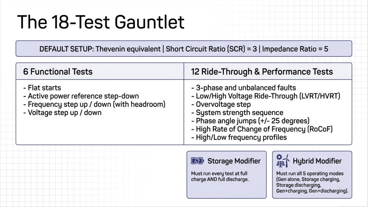
Unless a test specifies otherwise, the model is set up with a Thevenin equivalent at a short-circuit ratio of three and an impedance ratio of five. Storage projects run every test at full charge and full discharge. Hybrid plants run all five operating modes — generation alone, storage charging alone, storage discharging alone, generation with storage charging, and generation with storage discharging — with any inapplicable mode noted and justified.
| # | Test | Setup | What it proves |
|---|---|---|---|
| 1 | Flat start | Maximum facility output, unity power factor, default short-circuit ratio, fifteen seconds | Steady state reached within five seconds and held, with output variation no greater than a tenth of a megawatt or megavar |
| 2 | Active power reference step down | Step the plant controller reference from full to ninety percent at ten seconds | The model follows active power commands dynamically with reasonable response time, and reactive power stays in range |
| 3 | Frequency step up | Source frequency stepped up three tenths of a hertz | Primary frequency response in the correct direction with acceptable response time |
| 4 | Frequency step down with headroom | At eighty percent output, source frequency stepped down three tenths of a hertz | Downward frequency response when headroom exists — which is why this case runs at part load |
| 5 | Voltage step up | Source voltage stepped up three hundredths per unit | Reactive response in the correct direction, real power maintained |
| 6 | Voltage step down | Source voltage stepped down three hundredths per unit | The same, in the other direction |
| 7 | Three-phase-to-ground fault | Bolted fault at the point of interconnection, nine cycles, cleared without loss of elements | Balanced fault ride-through, appropriate reactive response, damped recovery and return to pre-fault output |
| 8 | Single line-to-ground fault | Bolted, nine cycles | Unbalanced fault ride-through and recovery |
| 9 | Line-to-line fault | Bolted, nine cycles | The other unbalanced case |
| 10 | Low-voltage ride-through profile | Voltage profile from the applicable protection settings standard, at a short-circuit ratio of fifty | Ride-through of the minimum low-voltage requirement, reactive current injection during the event, and no momentary cessation |
| 11 | Overvoltage ride-through | Step to 1.2 per unit for two tenths of a second, short-circuit ratio of fifty | High-voltage ride-through with reactive absorption, no momentary cessation, and damped recovery |
| 12 | High-voltage ride-through profile | Voltage profile from the applicable standard, short-circuit ratio of fifty | Ride-through of the minimum high-voltage requirement with reactive absorption |
| 13 | System strength | Short-circuit ratio sequence of five, three, one and a half, and one point two, changed under a three-cycle bolted fault, five seconds at each level | Positively damped response with no unit tripping at a short-circuit ratio of three and above |
| 14 | Phase angle change, plus twenty-five degrees | Instantaneous angle change at a short-circuit ratio of fifty | Ride-through with no unit trip, damped recovery, no momentary cessation |
| 15 | Phase angle change, minus twenty-five degrees | The same in the other direction | The same criteria |
| 16 | High rate of change of frequency | Sequence at five hertz per second down to 59.5, back to 60, up to 60.5 and back, five second intervals | Ride-through of a high rate-of-change sequence with damped recovery and no momentary cessation |
| 17 | High-frequency ride-through profile | Frequency profile from the applicable standard, short-circuit ratio of fifty | Ride-through and recovery with no momentary cessation |
| 18 | Low-frequency ride-through profile | Frequency profile from the applicable standard, short-circuit ratio of fifty | The same, on the low side |
8. The Acceptance Criteria That Fail Models
Three criteria appear repeatedly across the test set and account for most failures.
8.1 Damping Ratio of 0.3 or Greater
PJM sets an acceptable damping ratio of three tenths, referenced to the interconnection performance standard for inverter-based resources. It applies to the fault tests, the overvoltage test, the phase angle tests and the rate-of-change test. This is a numerical criterion, not a visual judgment, and it means the report must actually compute damping from the response rather than asserting that the plot looks stable.
8.2 Momentary Cessation
The treatment is nuanced and worth getting right. For the three fault tests, if the plant enters momentary cessation it must resume current injection in no fewer than five cycles following voltage recovery, and if momentary cessation cannot be eliminated because of equipment limitations, PJM must be notified when the report is submitted. For the ride-through profile tests, the overvoltage test, the phase angle tests and the rate-of-change test, the criterion is that momentary cessation is not observed — with the same notification route where equipment limitations prevent it.
The practical consequence is that momentary cessation behaviour is an equipment characteristic that has to be known before the tests are run. Discovering it during testing, late in the interconnection process, leaves a developer with a disclosure to make and limited options.
8.3 The System Strength Test
Test 13 is the one that most directly reflects why the guideline exists. The model is driven through progressively weaker system conditions — short-circuit ratio five, then three, then one and a half, then one point two — with each transition made under a three-cycle bolted fault. Acceptance requires a positively damped response with no unit tripping at a ratio of three and above.
Note what that acceptance criterion does and does not say. It requires stable behaviour down to a ratio of three. It does not require stability at one and a half or one point two — but the model is run there anyway, so PJM sees what happens. A plant that becomes unstable just below the acceptance threshold is visible in the results, and that visibility is the point.
9. Benchmarking Against PSS/E
The benchmark requirement is the mechanism by which PJM achieves its stated aim of catching conflicts between the two models before studies begin.
For as-designed submissions, the PSCAD and PSS/E signals must be overlaid and properly aligned for each signal plot of each required test. The stated objective is that the two models agree, so that the PSCAD model can be used confidently to address complex issues arising from the positive-sequence study. The required benchmark set is the six functional tests, the three-phase fault, the low-voltage ride-through profile and the high-voltage ride-through profile.
For as-built submissions the requirement inverts and expands. Model quality tests are benchmarked against the latest PSS/E user-defined model and library model results, and rather than listing what must be benchmarked, PJM lists what is excluded: the single line-to-ground fault, the line-to-line fault, and the two phase angle tests. Everything else is benchmarked — a substantially larger set than at as-designed stage.
The exclusions are logical. Those four cases involve unbalanced conditions or angle steps that a positive-sequence model cannot represent meaningfully, so a comparison would not be informative. It is a useful reminder of where the two model classes genuinely diverge.
Why the benchmark catches real problems
A PSCAD model and a PSS/E model of the same plant are frequently produced by different teams, sometimes at different times, occasionally by different vendors, and often from different parameter sets.
Overlaying their responses to the same disturbance is a blunt and effective test of whether they describe the same plant. Disagreement is common on first attempt, and finding it before the study is exactly the cost saving PJM is aiming at.
10. As-Designed and As-Built
The two stages ask different questions and the difference shapes the whole programme.
As-designed covers the cycle process and necessary studies — the model of the plant as it is intended to be built. Validation of a model assembled from library blocks is against actual hardware performance.
As-built is the model of the plant as it exists. The requirements tighten in three ways. Settings must match the site equipment, with default parameters explicitly unacceptable unless they match what is installed.
Validation of a non-real-code model is against actual field measurement data rather than hardware performance. And a Parameter Verification Report is required, comparing as-built site parameters — both plant controller and inverter — against the model parameters.
Beyond that sits the tuned model obligation: no later than one year after commercial operation, a tuned set of models aligned with the field tests specified in the model verification and validation standards, reflecting the actual dynamic response of the resource.
The through-line is that the model is expected to converge on the plant over time, and each stage narrows the permitted gap between them.
11. Deliverables and Submission Mechanics
A complete submission consists of four things.
- The PSCAD model. At as-built stage and beyond, the PSS/E user-defined model and library model are also submitted as part of the benchmark if not previously provided.
- The completed and signed PSCAD Model Requirements Checklist.
- The Model Quality Test and PSCAD-PSS/E Model Benchmark Reports.
- All cases and files used for every model quality test and benchmark report, so that PJM can rerun any of them for verification.
Files are placed in a folder, zipped, and uploaded through PJM’s data submission platform under the stability model or dynamic file location appropriate to the queue process. The upload limit is two hundred and fifty megabytes; larger packages go through secure transfer arranged with the project manager.
That size limit is worth planning around. A full test programme across five hybrid operating modes, at charge and discharge, with all cases and output files retained, generates a large package. Deciding late how to deliver it is an avoidable delay.
On plotting, the guideline is specific: RMS voltage in per unit, active power in megawatts, reactive power in megavars, and frequency in hertz; measured at both the point of connection or inverter terminals and the point of interconnection; and presented at two zoom levels — the full simulation period, and a focused view of the one to two seconds around the disturbance. Reports that omit the transient zoom or a measurement point create avoidable review cycles.
12. The Step-by-Step Process
The following is how the work sequences on a real project, from procurement through to the post-commercial-operation obligation.
STEP 1 Establish whether and when a model is required
Determine which submission pathway applies transition cycle with screening, Cycle 1 or beyond where every bulk-power-system-connected project submits, a necessary or surplus study, or an as-built verification. That determines the deadline and the deliverable set. Do this before anything else, because it fixes the schedule everything else has to meet.
STEP 2 Secure the model at procurement
Write the model deliverables into the equipment purchase specification: a PSCAD model meeting the thirty-five item checklist, real-code content where available, version identification, documentation and running instructions, contact details for modelling support, and the right to use and share the model with PJM. Tie delivery dates to project milestones. This is the single highest-leverage step in the whole process and it happens before any engineering.
STEP 3 Assemble the plant model
Build the aggregate representation up to the point of interconnection: aggregated generation or storage, aggregated generator transformer, equivalent collector branch, main step-up transformers, generator tie line, supplemental reactive devices, and station service load. Where the plant uses more than one inverter type, build a separate aggregate for each. Represent the external system as an AC source behind a Thevenin impedance.
STEP 4 Complete the checklist honestly
Work through all thirty-five items with the model supplier and record compliance. Where an item is not met, write the explanation in the comments column rather than leaving it blank. A checklist with candid gaps and explanations is a better submission than one that claims full compliance and fails a test and the explanations are what allow PJM to assess whether the gap matters for the studies it intends to run.
STEP 5 Confirm the PSS/E model is the current one
The benchmark compares the PSCAD model against the latest submitted PSS/E model. Establish which version that is and whether it reflects the current project configuration before running anything. Benchmarking against a superseded positive-sequence model wastes the whole test programme.
STEP 6 Set up the test environment
Configure the Thevenin source at the default short-circuit ratio of three and impedance ratio of five, with the tests that specify otherwise set up separately. Build the operating point matrix: for storage, full charge and full discharge; for hybrids, all five operating modes. Establish the plotting configuration four quantities, two measurement points, two zoom levels once, so every test produces consistent output.
STEP 7 Run the six functional tests
Flat start, active power reference step down, frequency step up, frequency step down with headroom, and voltage step up and down. These are quick and they surface fundamental problems early: a model that will not initialise cleanly or hold steady state has a defect that must be resolved before any ride-through work is worth doing.
STEP 8 Run the twelve ride-through and performance tests
The three fault cases, the low and high voltage ride-through profiles and the overvoltage step, the system strength sequence, the two phase angle changes, the rate-of-change sequence, and the high and low frequency profiles. Compute damping ratios rather than judging plots by eye, and record momentary cessation behaviour explicitly wherever it occurs.
STEP 9 Benchmark against PSS/E
Overlay and align the PSCAD and PSS/E signals for the required benchmark set — the six functional tests, the three-phase fault, and the two ride-through profiles at as-designed stage, or the substantially larger as-built set. Where the two disagree, resolve the discrepancy rather than presenting it, because an unexplained divergence is the finding PJM is looking for.
STEP 10 Assemble and submit the package
Model, signed checklist, quality test and benchmark reports, and every case and file used to produce the results. Check the package against the size limit and arrange secure transfer in advance if needed. Upload to the correct location for the queue process.
STEP 11 Manage change through the project
Any qualifying change — device updates, adding storage to a wind or solar plant, operating mode conversion — triggers a full resubmission with a report explaining what changed. Treat model configuration as a controlled item so that a settings change during construction is captured rather than discovered.
STEP 12 Close out at as-built and beyond
Produce the as-built model with settings matched to installed equipment, the expanded benchmark set, and the Parameter Verification Report comparing site parameters against model parameters. Then plan for the tuned model obligation within one year of commercial operation, aligned to the field tests the model verification standards specify.
13. Where Submissions Fail
| Failure | What happens | How to avoid it |
|---|---|---|
| The model does not exist | The vendor EMT model, or the right to share it with PJM, was never secured at procurement, and the deadline arrives with nothing to submit | Write model deliverables and usage rights into the purchase specification with dates tied to milestones |
| Generic plant controller | A generic representation is supplied where the guideline requires the actual controller unless the final controller exactly matches the generic model | Confirm at procurement that the plant controller model reflects the controller being installed, including measurement methods, delays and ride-through transitions |
| Simplified converter representation | A three-phase sinusoidal source is used where a full switching or firing-pulse representation is required | Check this specific item on the checklist before accepting the vendor package |
| Protection not represented | Protection is omitted or approximated, so the model rides through events the real plant would trip on | Require actual hardware code for protection features and diagnostic flags identifying which protection operated |
| PSS/E and PSCAD disagree | The benchmark shows the two models describing different plants, usually because they were built by different parties from different parameter sets | Confirm the current PSS/E model before testing and resolve divergence rather than submitting it |
| Momentary cessation discovered late | It appears in the ride-through tests, and the criteria for most of those tests require that it is not observed | Establish momentary cessation behaviour from the vendor early, and if it cannot be eliminated, plan the notification rather than being surprised by it |
| Incomplete package | Cases and files omitted, plots missing a measurement point or zoom level, or checklist items left blank | Build the package to the deliverables list and the plotting specification from the first test, not at the end |
| Settings drift at commissioning | The installed configuration differs from the studied model, which PJM treats as a qualified change affecting study validity | Put model configuration under change control and capture differences as they arise |
14. What This Connects To
This guideline does not sit alone, and a project team that treats it as an isolated deliverable will duplicate work.
- The positive-sequence model requirement under PJM’s existing dynamic model guidelines. The two are a pair, and the benchmark forces them to agree.
- The model verification and validation obligations in the applicable reliability standards, which drive the tuned model within one year of commercial operation and which require transmission planners and planning coordinators to establish requirements for both model types.
- The interconnection performance standard for inverter-based resources, which is the source of the damping ratio criterion and much of the underlying performance expectation.
- The reliability standard governing frequency and voltage ride-through for inverter-based resources, which takes effect on 1 October 2026 and which the ride-through test profiles relate directly to.
- The disturbance monitoring obligations that supply the recorded data by which real performance is later demonstrated.
- The facility change requirements, under which a difference between the studied model and the installed settings is a qualified change.
The efficient way to run this is as one modelling and compliance workstream with several outputs, rather than as a series of unrelated submissions to different parties.
15. Keentel PJM Modeling Services
Keentel Engineering supports developers, owners and their EPC partners through this process, from procurement specification to the post-commercial-operation obligation.
15.1 Model Development and Assembly
- Model deliverable and usage-rights requirements written into equipment purchase specifications, with delivery dates tied to project milestones.
- Assembly of the aggregate plant representation to the point of interconnection — generation or storage, transformers, equivalent collector, tie line, supplemental reactive devices and station service — including separate aggregates where multiple inverter types are present.
- Review of vendor-supplied models against the thirty-five item checklist, with gaps identified and explanations prepared before submission rather than discovered in review.
- Positive-sequence model development and reconciliation, so that the PSS/E and PSCAD models describe the same plant before benchmarking begins.
15.2 Testing, Benchmarking, and Reporting
- Execution of the full eighteen-case model quality test programme, across the operating point matrix required for storage and hybrid plants.
- Damping ratio computation, momentary cessation characterisation, and diagnosis of trips and instabilities against the model’s own diagnostic flags.
- PSCAD to PSS/E benchmarking with aligned overlays, and resolution of divergence between the two models.
- Model Quality Test and Benchmark Report preparation to the plotting specification, and package assembly against the deliverables list including all cases and files.
15.3 Studies and Interconnection Support
- Weak-grid and control interaction studies, sub-synchronous oscillation screening, and determination of the minimum system strength at which the plant is stable.
- Ride-through capability assessment at the point of interconnection, supporting both the interconnection obligation and the applicable reliability standard.
- Short-circuit, protective coordination, arc-flash, load flow, reactive capability, harmonic and stability studies, with inverter-based resources represented as current-limited sources.
- Interconnection application support and study-phase technical packages, and coordination with PJM and the transmission owner.
15.4 As-Built, Compliance, and Change Management
- As-built model development with settings matched to installed equipment, the expanded benchmark set, and Parameter Verification Report preparation.
- Model tuning against field test data for the post-commercial-operation obligation, and model verification and validation support under the applicable standards.
- Model and settings configuration control, so that changes during construction and commissioning are captured and the resubmission obligation is met deliberately.
- Owner’s engineer services, review of EPC and vendor model packages, and QA/QC of third-party study and model submissions.
Keentel Engineering holds a Florida Certificate of Authorization and maintains offices in Tampa, Austin, Sacramento, and Baltimore, supporting projects across the interconnections.
17. Frequently Asked Questions
Q1. What is this document and when was it issued?
The PJM EMT Model Development Guidelines for Inverter-Based Resources, Revision 0, issued 5 March 2026 by PJM’s System Planning Division. It sets out what an electromagnetic transient model must contain, how it is tested, how it is benchmarked against the positive-sequence model, and what a complete submission includes.
Q2. Why does PJM need an EMT model at all?
Because positive-sequence phasor-domain models are built for the frequency range typical of stability studies — PJM cites roughly a tenth of a hertz to ten hertz — and cannot represent switching transients, harmonics, torsional interaction and the fast control behaviour that governs inverter interaction with a weak grid. PJM names sub-cycle overvoltage and sub-synchronous oscillation as the dynamics it is seeing.
Q3. Who does it apply to?
All inverter-based resources: solar photovoltaic, battery energy storage, Type III and Type IV wind, and co-located and hybrid plants such as solar plus storage or wind plus storage.
Q4. What software format is required?
A format compatible with the PSCAD and EMTDC simulation environment — the project, case and library file types. The positive-sequence model is submitted separately in PSS/E under PJM’s existing dynamic model guidelines.
Q5. When is the model due?
It depends on the pathway. In Transition Cycle 2, PJM screens at the start of Phase II for projects in low system strength areas and notifies those developers, with submission at Decision Point II. From Cycle 1 onward, all bulk-power-system-connected projects submit at Decision Point II regardless of location. Necessary, surplus and non-cycle requests submit with the study request.
Q6. Our last project was not screened in. Does that mean the next one is exempt?
No. The screening applies to the transition cycle. From Cycle 1 onward there is no screening — every bulk-power-system-connected project submits.
Q7. What must the model represent?
An aggregate representation up to the point of interconnection: aggregated generation or storage, aggregated generator transformer, equivalent collector branch, main step-up transformers, generator tie line, supplemental reactive devices where present, and station service load. The external system is an AC source behind a Thevenin impedance.
Q8. We have two inverter types on site. One aggregate or two?
Two. Where a plant uses multiple inverter types or designs, a separate aggregate representation is required for each.
Q9. What is the model requirements checklist?
A thirty-five item list covering documentation, accuracy, usability and efficiency, completed and signed by the supplier of the model. Every item must be reviewed, and where the model does not meet a requirement, an explanation is required in the comments column.
Q10. Can we use a model built from standard library blocks?
Yes, with a condition. PJM recommends real-code models embedding actual hardware code. A model assembled from library blocks or translated from control block diagrams requires validation against actual hardware performance at the as-designed stage, and against field measurement data at as-built.
Q11. Is a simplified converter representation acceptable?
No. A full switching-device representation or a voltage source interface that mimics switching, such as a firing-pulse-based model, is required. A three-phase sinusoidal source representation is explicitly not acceptable.
Q12. Can we supply a generic plant controller model?
Only if the final plant controller is designed to exactly match the generic model. Otherwise the plant controller must be represented in detail — measurement methods, communication delays, transitions into and out of ride-through modes, and settable parameters. This is one of the more commonly missed requirements.
Q13. Does protection have to be modelled?
Yes, in detail, for both balanced and unbalanced faults — overvoltage and undervoltage on individual phase and RMS, frequency, DC bus voltage, converter overcurrent and other inverter-specific protections. Actual hardware code is required, and the protections must be disableable for diagnostic purposes.
Q14. What time step must the model support?
It must run across the range from five to twenty microseconds, with ten microseconds recommended, and must not depend on a specific time step.
Q15. How many tests are there and what are they?
Eighteen. Six functional tests — flat start, active power reference step down, frequency step up and step down with headroom, and voltage step up and down. Twelve ride-through and performance tests — three fault cases, low and high voltage ride-through profiles, an overvoltage step, the system strength sequence, two phase angle changes, a rate-of-change-of-frequency sequence, and high and low frequency profiles.
Q16. What is the default test setup?
A Thevenin equivalent at a short-circuit ratio of three and an impedance ratio of five, unless a test specifies otherwise. Several ride-through tests specify a ratio of fifty, and the system strength test runs its own sequence.
Q17. What extra testing applies to storage and hybrid plants?
Storage projects run every test at full charge and full discharge. Hybrid plants run all five operating modes — generation alone, storage charging alone, storage discharging alone, generation with storage charging, and generation with storage discharging — with any inapplicable mode noted and justified in th report.
Q18. What damping ratio is acceptable?
Three tenths or greater, referenced to the interconnection performance standard for inverter-based resources. It applies to the fault tests, the overvoltage test, the phase angle tests and the rate-of-change test. It is a computed value, not a visual assessment of a plot.
Q19. How is momentary cessation treated?
It differs by test. For the three fault cases, if the plant enters momentary cessation it must resume current injection in no fewer than five cycles after voltage recovery. For the ride-through profiles, the overvoltage test, the phase angle tests and the rate-of-change test, the criterion is that momentary cessation is not observed. In all cases, if it cannot be eliminated because of equipment limitations, PJM must be notified with the report.
Q20. What does the system strength test require?
The model runs through short-circuit ratios of five, three, one and a half, and one point two, with each transition made under a three-cycle bolted fault and five seconds held at each level. Acceptance requires a positively damped response with no unit tripping at a ratio of three and above — but the model is run to the lower ratios anyway, so PJM sees the behaviour there.
Q21. Which tests must be benchmarked against PSS/E?
At as-designed stage, the six functional tests, the three-phase fault, and the low and high voltage ride-through profiles. At as-built the requirement is stated as exclusions instead: the single line-to-ground fault, the line-to-line fault and the two phase angle tests are excluded, and everything else is benchmarked.
Q22. Why are those four excluded at as-built?
They involve unbalanced conditions or instantaneous angle steps that a positive-sequence model cannot represent meaningfully, so the comparison would not be informative. It is a useful marker of where the two model classes genuinely diverge.
Q23. What makes a submission complete?
Four things: the PSCAD model — with the PSS/E user-defined and library models at as-built if not previously provided; the signed model requirements checklist; the model quality test and benchmark reports; and every case and file used to produce the results, so PJM can rerun them.
Q24. Are there submission mechanics to plan for?
Yes. Files are zipped and uploaded through PJM’s data submission platform, with a two hundred and fifty megabyte limit and secure transfer arranged through the project manager above that. A full hybrid test programme with all cases and output files retained can exceed it, so decide the delivery route early.
Q25. What happens after commercial operation?
No later than one year after commercial operation begins, a tuned set of models must be provided, aligned with the field tests specified in the applicable model verification and validation standards and reflecting the actual dynamic response of the resource. Separately, any difference between the studied model and the installed settings is treated as a qualified change affecting study validity.
16. References and Further Reading
The primary source for this paper is the PJM guideline itself. PJM documents are revised, and this paper describes Revision 0; check for a later revision before relying on any requirement here.
PJM Documents
- PJM EMT Model Development Guidelines for Inverter-Based Resources, Revision 0, System Planning Division, 5 March 2026, together with the standalone PSCAD Model Requirements Checklist — PJM Interconnection
- PJM Dynamic Model Development Guidelines, covering the positive-sequence model requirements in PSS/E format — PJM Interconnection
- PJM interconnection process materials, including the cycle process, decision points and the data submission platform — PJM Interconnection
NERC Guidance and Standards
- NERC Reliability Guideline, Electromagnetic Transient Modeling for BPS-Connected Inverter-Based Resources — Recommended Model Requirements and Verification Practices, March 2023 — North American Electric Reliability Corporation
- NERC Level 3 Alert on inverter-based resource performance and modelling, issued May 2025 — No
NERC Reliability Standards — including the MOD series covering model data, verification and validation, the PRC series covering protection settings, ride-through, disturbance monitoring and post-event analysis, and the FAC series covering facility changes — North American Electric Reliability Corporation
Industry Standards and Guidance
- IEEE Std 2800-2022, Standard for Interconnection and Interoperability of Inverter-Based Resources Interconnecting with Associated Transmission Electric Power Systems — the source of the damping ratio criterion referenced in the test acceptance criteria — IEEE Standards Association
- IEEE Std 1547-2018, Standard for Interconnection and Interoperability of Distributed Energy Resources with Associated Electric
Power Systems
Interfaces — IEEE Standards Association
- WECC Modeling and Validation Subcommittee, Inverter-Based Resources Power Plant Modeling and Validation Guideline — Western Electricity Coordinating Council
Notice and Disclaimer
This document is original technical content prepared by Keentel Engineering LLC for general professional information. It is not legal, regulatory, or project-specific engineering advice, and it does not constitute a registration determination, an applicability determination, a compliance determination, or a design for any facility.
Facts about events, dates, standards, thresholds and programme status are taken from the three NERC publications identified in the References section, as published. This programme is moving quickly under a regulatory deadline: registry criteria, standard content, comment periods and effective dates are subject to change, and several matters described here were expressly stated by NERC as not yet final. Verify the current position with NERC, the applicable Regional Entity and the interconnecting utility before making any decision.
Analysis, inference, engineering commentary and the recommended actions in this document are Keentel Engineering’s own assessment and should not be attributed to NERC, any Regional Entity, any regulator, or any party named or referenced.
Descriptions of facility protection and transfer scheme behaviour are general engineering discussion; any change to a protection or control scheme must be made by qualified persons with the equipment manufacturer and against the actual tolerance of the equipment being protected.
Keentel Engineering LLC is an independent engineering consultancy. Reference to any regulator, reliability organisation, regional entity, standard, industry organisation, utility, or facility in this document does not imply affiliation with, endorsement by, or sponsorship from any such organisation.

About the Author:
Sandip "Sonny" R. Patel, P.E.
IEEE Senior Member · Founder & CEO, Keentel Engineering
In 1995, Sonny Patel earned his Electrical Engineering degree from the University of Illinois. But degrees don't build legacies — action does.
For three decades, he has worked the power industry from every side of the table: 16 years as a utility engineer at Exelon/Commonwealth Edison; generation leadership across hydroelectric, industrial steam turbine, and a 9 GW renewable fleet; NERC Regional Entity Senior Compliance Engineer and Audit Team Lead, auditing some of the nation's largest utilities; and testing and commissioning lead on equipment up to 765 kV — the very top of the North American grid.Utility. Generator. Regulator. Consultant. Few engineers have seen all four seats. Fewer still have sat in them.
His experience spans nuclear, hydro, conventional generation, renewables, oil and gas, mining — and today's data centers, where he is authoring a three-book series on data center design. He is a Licensed Professional Engineer in six states and a Licensed Electrical Contractor in Florida (Unlimited EC) — he doesn't just design the work; he's qualified to stand behind its execution.Today, as Founder and CEO of Keentel Engineering, Sonny leads a nationwide team of engineers delivering substation design, power system studies, NERC compliance, and commissioning — done right, coast to coast.Three decades. Every side of the table. One standard: accountable engineering.
Services

Let's Discuss Your Project
Let's book a call to discuss your electrical engineering project that we can help you with.
About the Author:
Sandip "Sonny" R. Patel, P.E.
IEEE Senior Member · Founder & CEO, Keentel Engineering
In 1995, Sonny Patel earned his Electrical Engineering degree from the University of Illinois. But degrees don't build legacies — action does.
For three decades, he has worked the power industry from every side of the table: 16 years as a utility engineer at Exelon/Commonwealth Edison; generation leadership across hydroelectric, industrial steam turbine, and a 9 GW renewable fleet; NERC Regional Entity Senior Compliance Engineer and Audit Team Lead, auditing some of the nation's largest utilities; and testing and commissioning lead on equipment up to 765 kV — the very top of the North American grid.
Utility. Generator. Regulator. Consultant. Few engineers have seen all four seats. Fewer still have sat in them.
His experience spans nuclear, hydro, conventional generation, renewables, oil and gas, mining — and today's data centers, where he is authoring a three-book series on data center design. He is a Licensed Professional Engineer in six states and a Licensed Electrical Contractor in Florida (Unlimited EC) — he doesn't just design the work; he's qualified to stand behind its execution.
Today, as Founder and CEO of Keentel Engineering, Sonny leads a nationwide team of engineers delivering substation design, power system studies, NERC compliance, and commissioning — done right, coast to coast.Three decades. Every side of the table. One standard: accountable engineering.
Leave a Comment
Thank you for contacting us.
We will get back to you as soon as possible.
We will get back to you as soon as possible.
Oops, there was an error sending your message.
Please try again later.
Please try again later.
Related Posts
By SANDIP R PATEL
•
October 23, 2026
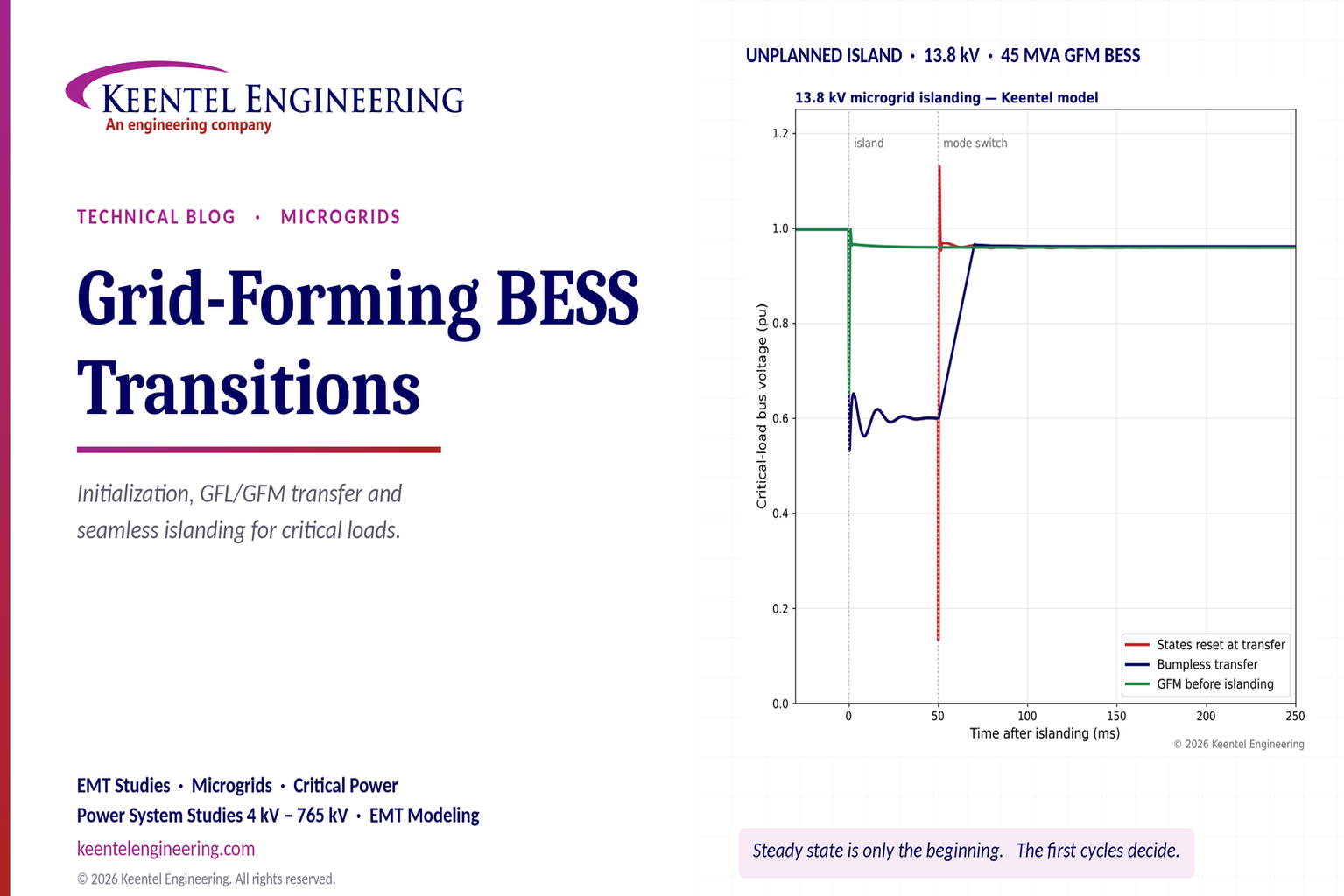
Explore grid-forming BESS initialization, GFL-to-GFM transitions, seamless islanding, EMT simulations, current limiting and microgrid protection.
By SANDIP R PATEL
•
October 23, 2026
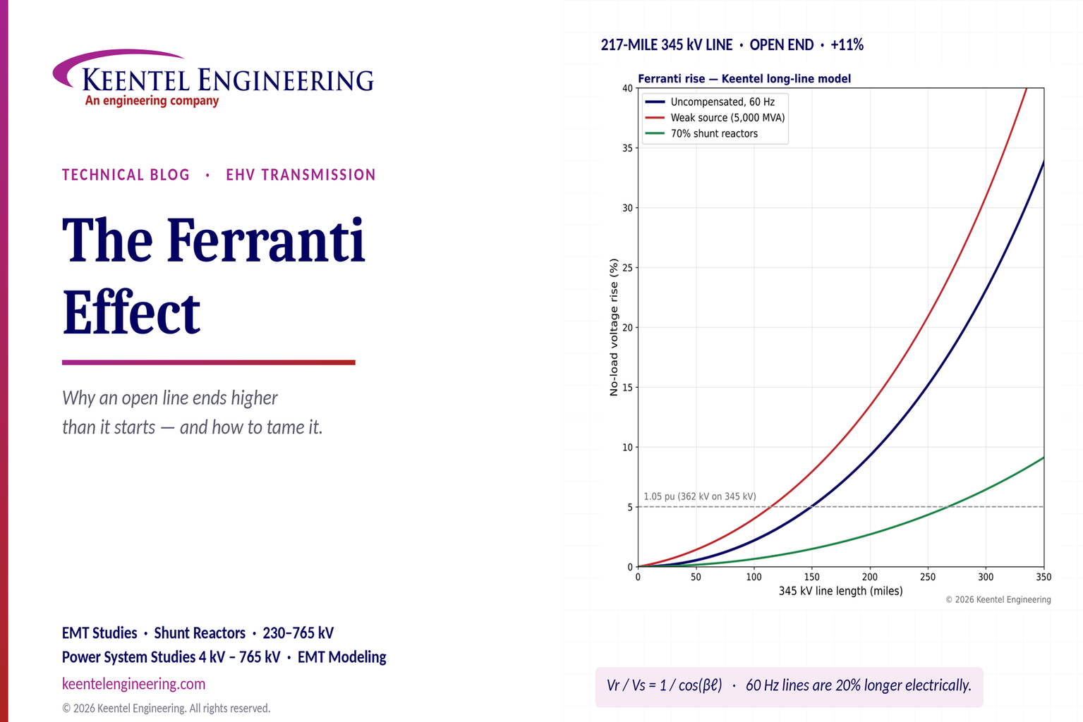
Explore the Ferranti effect in EHV transmission lines: voltage rise, 345 kV examples, switching overvoltages, shunt reactor sizing and mitigation.
By SANDIP R PATEL
•
October 23, 2026
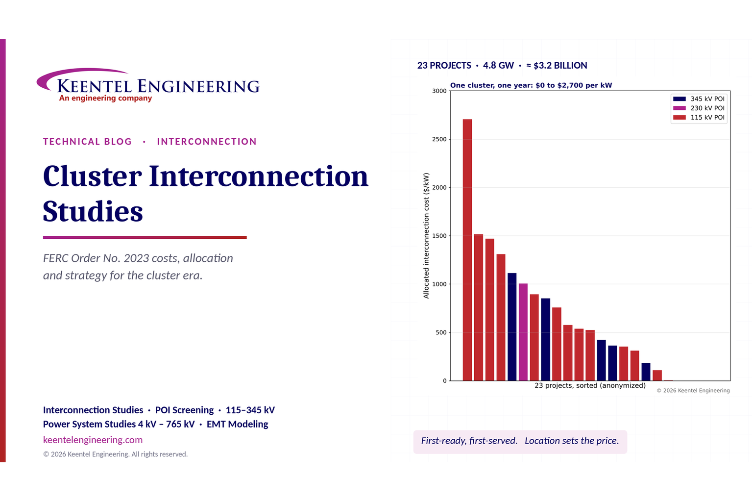
Explore cluster interconnection studies under FERC Order 2023, including network upgrades, cost allocation, withdrawal penalties and developer strategy.
By SANDIP R PATEL
•
October 21, 2026
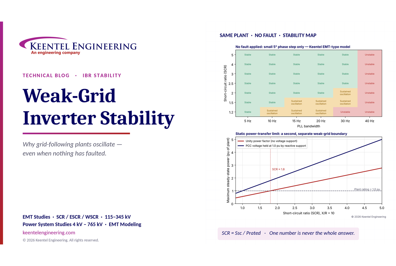
Learn why grid-following inverters become unstable without grid faults. Explore SCR, PLL interactions, EMT studies, grid strength, and mitigation.
By SANDIP R PATEL
•
October 21, 2026
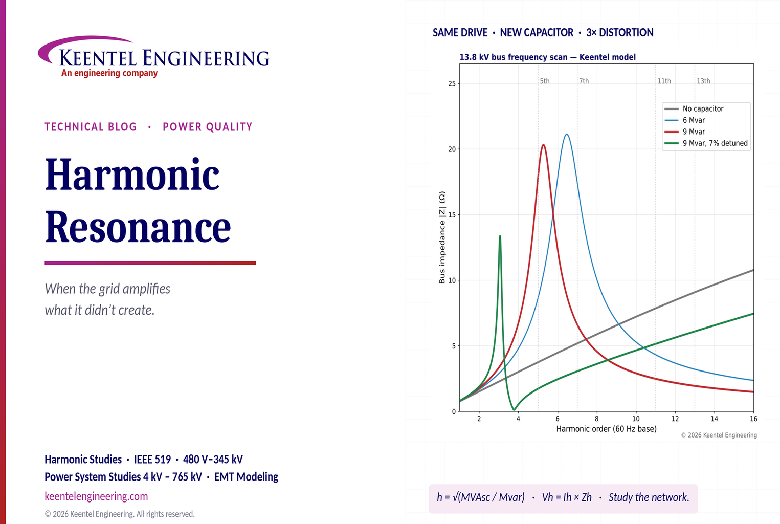
Learn how harmonic resonance amplifies distortion in power systems. Explore capacitor banks, detuned reactors, frequency scans, and IEEE 519 solutions.
By SANDIP R PATEL
•
October 20, 2026
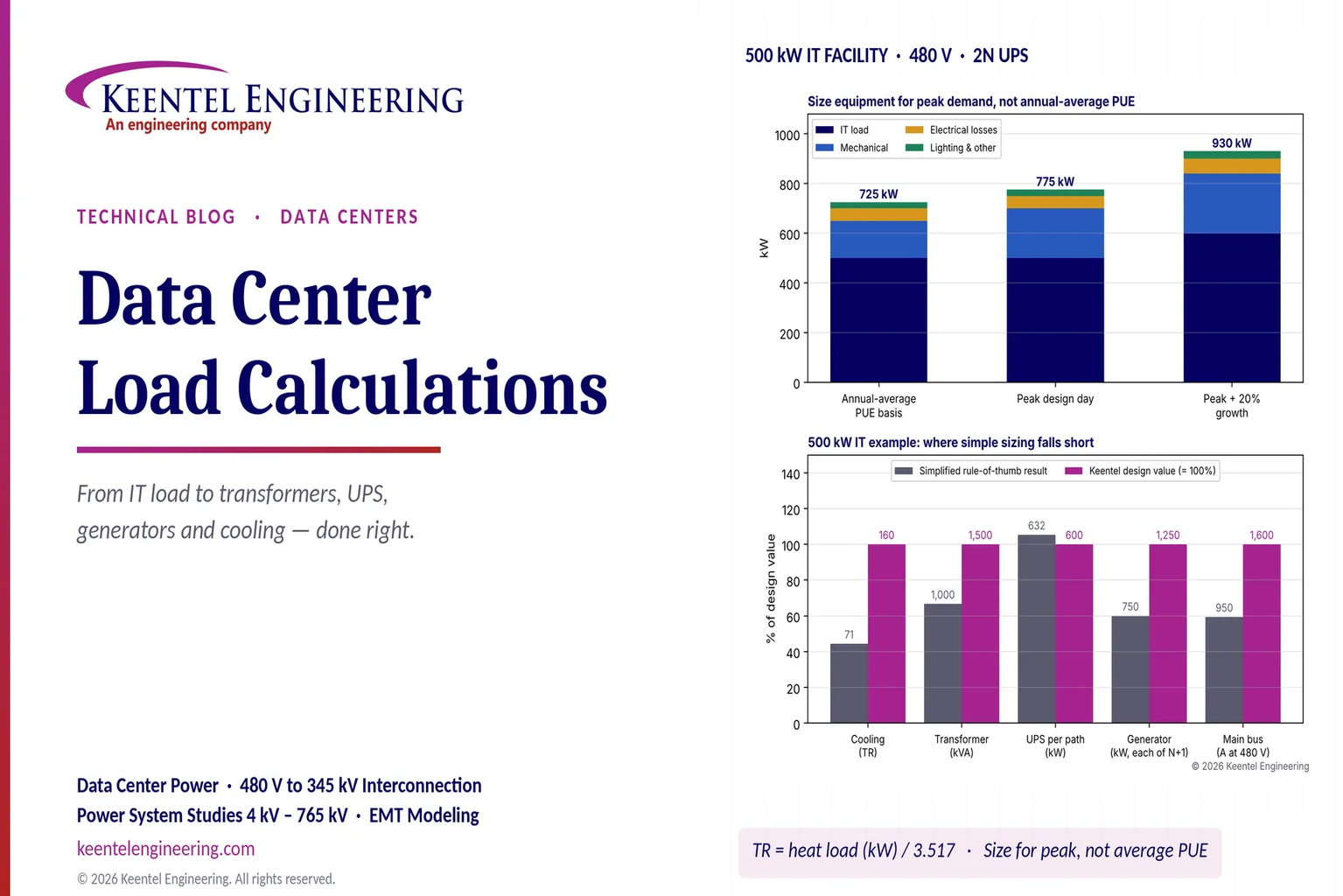
Learn data center electrical load calculations, including IT demand, PUE, UPS and generator sizing, cooling loads, redundancy, and worked US examples.
By SANDIP R PATEL
•
October 20, 2026
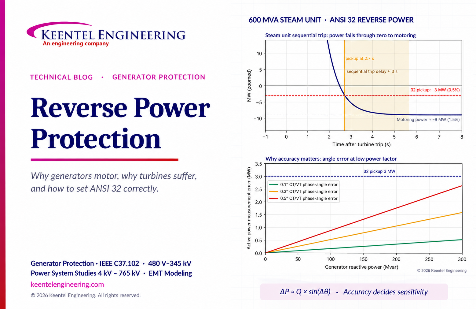
Learn reverse power protection (ANSI 32), generator motoring, relay pickup settings, time delays, sequential tripping and testing for US power plants.

By Team 2 Dexora
•
October 20, 2026
Explore grounding system testing with Keentel Engineering. Learn IEEE 80/81 methods, soil resistivity, ground resistance, and touch and step voltage safety.

By SANDIP R PATEL
•
October 13, 2026
Plan data center capacity with land screening, MW-per-acre estimates, grid power availability and interconnection feasibility studies from Keentel Engineering.





