
A Coordinated Electric System Interconnection Review—the utility’s deep-dive on technical and cost impacts of your project.
Challenge: Frequent false tripping using conventional electromechanical relays
Solution: SEL-487E integration with multi-terminal differential protection and dynamic inrush restraint
Result: 90% reduction in false trips, saving over $250,000 in downtime
Risk Mitigation for Emerging Large Loads: What NERC's May 2026 Reliability Guideline Means for Your Interconnection
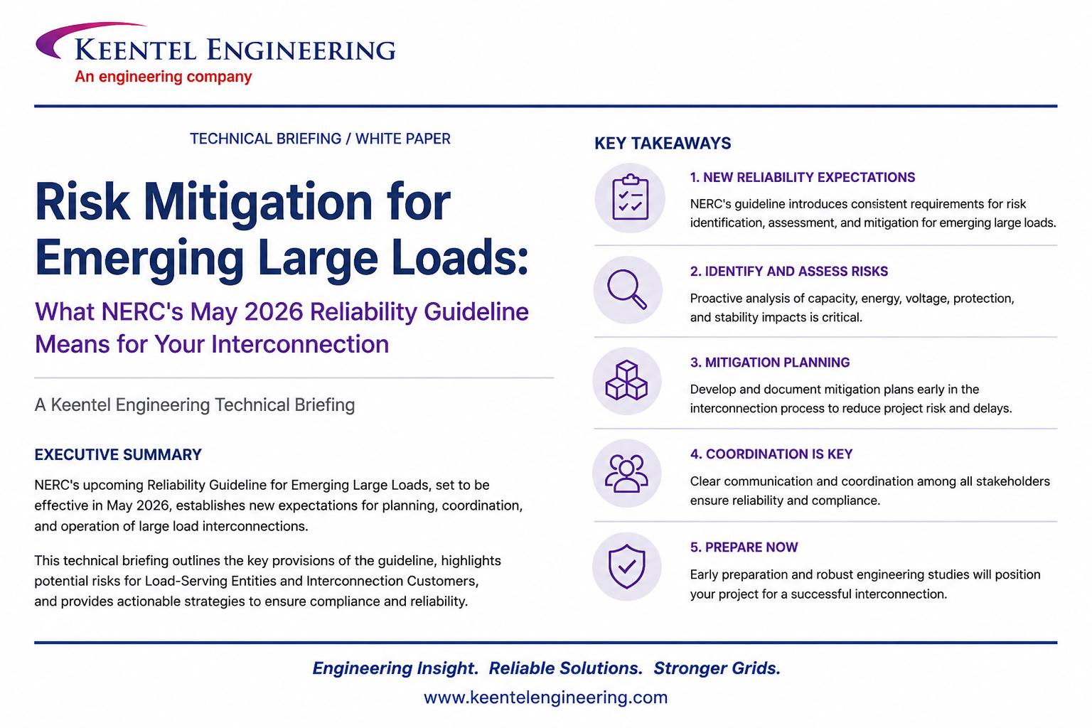
May 25, 2026 | Blog
In side NERC's New Reliability Guideline for Large Loads
The Grid Has a New Problem
In May 2026, the North American Electric Reliability Corporation (NERC) finalized its Reliability Guideline: Risk Mitigation for Emerging Large Loads - a 47-page document that quietly rewrites the rules of engagement between large industrial customers and the bulk power system (BPS). If you operate, own, develop, or design a data center, AI training campus, cryptocurrency mining facility, hydrogen electrolyzer plant, arc furnace, or any other large industrial load seeking interconnection, this guideline applies to you.
The headline takeaway is blunt: large loads are no longer passive consumers. They are active participants in grid reliability — and the era of "plug it in and forget it" interconnection is over.
At Keentel Engineering, we have watched this shift accelerate over the last 36 months.
Customer-initiated load reduction (CILR) events in ERCOT, voltage-sensitive crypto load reductions documented by NERC in January 2026, and oscillation events traced back to AI training data centers have transformed what was once a theoretical concern into a measurable, repeatable reliability risk. NERC's guideline is the industry's structured response, and understanding it is now essential for anyone integrating loads above the thresholds that planners are now scrutinizing.
Why This Guideline Exists
NERC's Large Loads Working Group (LLWG) authored two prior white papers Characteristics and Risks of Emerging Large Loads and Assessment of Gaps in Existing Practices, Requirements, and Reliability Standards for Emerging Large Loads — that identified specific failure modes:
CILR events where transmission-remote faults cause hundreds of megawatts of voltage- sensitive load to simultaneously disconnect from the grid, even though the loads
themselves never lost service.
Forced oscillations introduced by cyclical loads (notably AI training workloads and electric arc furnaces) interacting with natural electromechanical modes between 0.1 and 2 Hz.
Resource adequacy mismatches when demand outpaces transmission and generation buildout.
Cascading overfrequency conditions that can trip generators after a CILR event creates a sudden generation surplus.
The guideline addresses these by mapping specific recommendations to twelve entity types — including Planning Coordinators (PC), Transmission Planners (TP), Transmission Owners (TO), Balancing Authorities (BA), Reliability Coordinators (RC), large load entities, and original equipment manufacturers (OEMs).
The Nine Chapters: A Practical Walkthrough
Chapter 1: Data Collection and Modeling
This is the foundation of everything else. NERC defines three project lifecycle stages interconnection evaluation, integration and commissioning, and operations - and prescribes what data must be collected at each. The headline requirements:
Steady-state data: peak demand, buildout schedule (MW energized monthly or yearly),
power factor across loading levels, one-line diagrams, reactive devices.
Dynamic modeling: site-specific positive-sequence phasor domain (PSPD) models that capture protection devices, disconnection and reconnection thresholds, voltage and frequency ride-through behavior, IT load makeup, motor load, VFD content, and any oscillation-smoothing hardware or software.
Electromagnetic transient (EMT) models: coordinated with the OEM, required by the TP and PC where weak grids, power electronics, or sub-synchronous interactions are in play.
High-speed monitoring devices: fault recording (FR), continuous dynamic disturbance recording (DDR), and sequence of events recording (SER) at the high side of the main power transformer, with specifications similar to PRC-002 and PRC-028.
The data must be updated through three model states: as-designed, as-built, and as-left-with attestation that parameters represent installed equipment, not vendor defaults.
Chapter 2: Interconnection Studies and Processes
TPs and PCs are directed to perform steady-state, dynamic (PSPD and EMT where needed), and short-circuit studies that explicitly account for collective tripping of electrically close facilities. The guideline introduces EMT screening criteria including weak grid conditions (short-circuit ratio of two or less), large power electronic devices, series capacitors, and load profiles with significant fluctuations in the 5-60 Hz range.
A new concept - triggers for re-study — formalizes what happens when a project changes mid- stream. ERCOT has documented cases where a project entered interconnection as a data center and emerged as a cryptocurrency mining facility. The guideline now requires PCs to publish criteria that catch these pivots.
Chapter 3: Long-Term Planning and Resource Adequacy
Resource Planners (RPs) are asked to model delayed generation interconnections, simulate operational constraints and flexibility of large loads (including behind-the-meter generation and storage), and use probabilistic metrics beyond loss of load expectation — including loss of load hours, expected unserved energy, and conditional value at risk.
The guideline also explicitly calls out fuel supply common-mode dependency risk, particularly for gas-dependent regions where large loads with high load factors are clustering.
Chapter 4: Operations and Balancing
This chapter introduces the most operationally consequential requirements:
Commissioning processes that verify SCADA and PMU telemetry, demand-response capability, ramp ability, and maximum consumption - with re-testing as tiered buildouts add capacity.
Short-term forecasting with near-term hourly net-load forecasts and operating plans for 7- 10 days ahead, aligned with BAL-007 Near-Term Energy Reliability Assessments.
Most-severe load contingency (analogous to BAL-002's most-severe single contingency for generators) that BAs must identify and incorporate into unit commitment and reserve planning.
24/7 operational contacts at large load facilities for coordination with TOPS, BAs, and RCS.
Training and adherence to operating instructions modeled on COM-001, COM-002, PER- 005, TOP-001, and IRO-001-standards that historically applied only to generators.
Chapter 5: Stability
Voltage and frequency disturbance performance gets a dedicated chapter because CILR is the single most consequential demonstrated risk. The guideline recommends ride-through requirements coordinated on a per-interconnection basis, with attention to:
RoCoF (rate-of-change-of-frequency) ride-through.
Phase-jump considerations.
Low-voltage and high-voltage ride-through aligned with PRC-019, PRC-024, and PRC-029.
Overfrequency limits (60.5 Hz Eastern Interconnection continuous; 60.6 Hz for all others;
ERCOT has set 60.4 Hz as its transient limit).
Oscillation attenuation metrics for loads in the 0.1-2 Hz electromechanical range.
Angular stability risks for large loads co-located with generation in weak transmission
corridors.
Chapter 6: Power Quality
Harmonic injection up to the 100th harmonic order should be characterized, with IEEE Standard 519-2022 limits incorporated into interconnection requirements under FAC-001. The guideline
specifies that a 10% or greater increase in projected harmonic emissions from late-stage design changes should trigger re-study.
Chapter 7: Physical and Cyber Security
Aligns large load interconnection with the CIP-005, CIP-007, CIP-008, CIP-013, and CIP-014 frameworks - including supply chain risk management, network segmentation between OT and IT, encrypted communications, joint incident response plans, and participation in E-ISAC
GridEx exercises.
Chapter 8: Resilience, System Restoration, and Load Shedding
EOP-011, PRC-006, and PRC-010 implications are profound. When a single large load can equal or exceed the load on entire UFLS feeders, the math behind 25%-of-load UFLS programs breaks down. The guideline recommends dynamic load shed allocation, partial load shedding capability (segmenting large loads into controllable blocks), and review of the five-year UFLS/UVLS assessment cycle in regions with rapid load growth.
Chapter 9: Conclusion and Appendix A
Appendix A maps every recommendation to a responsibility matrix — Coordinate, Lead, Monitor, Provide, or Specify Requirements - across the twelve entity types. It is the single most useful operational document in the guideline and should be the starting point for any internal compliance gap assessment.
What Changes for Your Project - In Practical Terms
If your interconnection is in flight, expect:
1. More data requests, earlier in the process. Dynamic models, OEM test reports, harmonic
spectra, and ride-through curves that were previously requested at commissioning are now expected during interconnection evaluation.
2. Re-study triggers you didn't anticipate. Changing your computational mix (cloud → AI
training), swapping UPS vendors, or modifying buildout schedules can now require a full re-study.
3. Operational obligations during operations. Day-ahead operating plans, 24/7 contacts, real-
time telemetry, and outage reporting are no longer optional.
4. Commissioning that doesn't end. Repeat testing as new tiers energize, with model
validation against measured event data.
5. Coordination with neighboring entities. If your project sits near a seam, expect data
sharing across PC/BA/RC boundaries.
How Keentel Engineering Helps
Our team has supported large load interconnections across ERCOT, PJM, MISO, WECC, and
SERC footprints. We deliver:
Dynamic modeling packages (PSPD and EMT) that satisfy MOD-032 and FAC-002 requirements and pass model quality assessments.
Voltage ride-through compliance studies that align facility protection and control settings with TO interconnection requirements.
Harmonic studies and mitigation design up to the 100th harmonic order, including filter and STATCOM specification.
Commissioning support including FR/DDR/SER device specification, validation testing, and model verification reports.
Post-event analysis comparing measured response with simulated behavior for ongoing model validation.
Operational integration support including telemetry architecture, day-ahead forecasting protocols, and 24/7 contact frameworks.
The guideline is voluntary today. The Reliability Standards being drafted in parallel will not be. Projects that align with the guideline now will move through interconnection faster, avoid late- stage re-study delays, and operate without the regulatory exposure that's coming.
Anonymous Case Studies
Case Study 1: AI Training Campus in a Weak Grid Corridor (PJM Footprint)
Profile
A hyperscale operator planned a 380 MW AI training campus on a brownfield industrial site approximately 14 miles from the nearest 500 kV substation. The site offered favorable land cost and existing fiber, but the local 230 kV ring was characterized by long radial segments and limited synchronous generation within 60 miles. Initial short-circuit ratio (SCR) at the proposed POI calculated below 2.5 under normal topology and dropped below 2.0 under credible N-1 contingencies.
The Challenge
The TP's initial PSPD screening identified weak grid conditions warranting EMT analysis. During EMT studies, GPU cycling at training-job boundaries produced real power oscillations in the 0.7 to 1.4 Hz range - directly inside the local electromechanical mode of two nearby gas- fired combined cycle plants. Simulation showed underdamped oscillation growth that would have exceeded TP-defined attenuation thresholds within roughly 40 seconds following representative training workload transitions. Concurrently, the proposed UPS transfer logic exhibited a low-voltage ride-through curve that would have caused a 220 MW step disconnection during a normally cleared three-phase fault on a 230 kV bus 22 miles away.
Keentel Engineering's Engagement
We supported the operator across three workstreams over an eight-month engagement:
1. EMT model development and OEM coordination. We collaborated with the GPU OEM, UPS vendor, and rack-level controller supplier to assemble a site-specific EMT model representing the actual control hierarchies not vendor default parameters. The model included delay logic, reconnection criteria, and voltage and frequency tolerance windows tied to documented equipment manuals.
2. Oscillation mitigation design. We specified a rack-level energy storage and workload-
smoothing layer that reduced inter-job power swings from approximately ±55 MW peak-to- peak to ±8 MW peak-to-peak, validated in EMT simulation against the local electromechanical mode. The mitigation combined software workload staggering, GPU power smoothing, and 12 MWh of distributed lithium-ion energy storage operating in a power-quality firming mode.
3. Ride-through coordination. We revised the UPS transfer logic to a coordinated low-voltage
ride-through profile aligned with the per-interconnection requirements the TO and TP were standardizing. The revised profile allowed the facility to ride through faults clearing within 9 cycles at 230 kV without triggering UPS-driven disconnection.
Outcome
The TP accepted the revised EMT and PSPD models for the FAC-002 dynamic study. The interconnection agreement was finalized approximately five months later than the operator's original schedule, but without the 18 to 24-month delay that competing weak grid sites in the region had experienced. The facility energized in tiered 60 MW blocks across a 14-month buildout. Post-commissioning DDR and PMU data validated the simulated oscillation response within 6% of measured peak-to-peak amplitude across the first eight months of operation.
Lessons
―
Early EMT engagement — before site control was finalized — would have reduced schedule risk further. Operators evaluating weak grid sites should treat EMT screening criteria as a gating decision, not a downstream study activity.
Case Study 2: Cryptocurrency Mining Facility Mid-Project Pivot (ERCOT Footprint)
Profile
A developer had received approval of an interconnection request application for a 220 MW data center at a substation in the ERCOT footprint. Eighteen months into integration — with the substation built, the main power transformer energized, and the facility electrical room nearing completion — the developer reached an agreement with an end customer that converted the project's operational profile from a traditional cloud data center to an application-specific integrated circuit (ASIC) cryptocurrency mining facility.
The Challenge
The change in operational profile was a textbook qualified change under the criteria NERC's guideline now recommends. ASIC mining loads exhibit fundamentally different voltage sensitivity, power factor behavior, and ride-through characteristics than diversified cloud loads. The original dynamic model — built on default parameters representing motor and IT load mix - was no longer representative. The TP requested a re-study and a full data refresh including new harmonic spectra, updated ride-through curves, and as-built dynamic model parameters.
The developer faced two timelines: an aggressive energization milestone tied to financing, and a re-study timeline that the TP estimated at four to six months. A delay would have triggered material adverse change provisions in the financing.
Keentel Engineering's Engagement
We were retained as the developer's technical lead for the re-study coordination. Our engagement covered four areas:
1. Rapid data assembly. Within three weeks, we collected and verified harmonic spectra (up
to the 100th harmonic order) from the ASIC OEM, ride-through documentation from the
rectifier and PDU vendors, and a revised one-line diagram reflecting the actual installed
equipment. We provided attestation that the as-built model parameters represented the installed equipment rather than vendor defaults.
2. Dynamic model verification. We benchmarked the PSPD model against an EMT model of
the facility, satisfying the TP's emerging model quality assessment criteria. The PSPD model demonstrated a low-voltage ride-through profile with a defined disconnection threshold and a documented reconnection ramp rate.
3. CILR contingency support. Because the facility was identified as a potential contributor to the most-severe load contingency for the local TOP, we supported the TOP and BA with simulations showing the aggregate impact of the facility under representative faults. The simulations demonstrated that with the new ride-through profile, the facility would contribute no more than approximately 75 MW of CILR in the worst credible case
the BA's reserve coordination tolerance.
within
4. Power quality compliance. Initial harmonic analysis showed projected emissions
exceeding the TO's IEEE 519-2022 alignment at the 11th, 13th, and 23rd harmonic orders. We designed a passive filter bank specification that, when installed, brought all current and voltage distortion within limits — verified in simulation and later confirmed by commissioning measurements.
Outcome
The re-study completed in 11 weeks against the TP's original 4-to-6-month estimate, with the difference attributable to pre-assembled data and a verified model package that allowed the TP to focus on system-level study rather than parameter validation. The facility energized within six weeks of the original target, with the financing milestone preserved.
Lessons
The guideline's emphasis on early identification of "specific model data and design decisions that are most crucial for accurate BPS reliability assessments" is not theoretical - it directly determines whether mid-project pivots can be absorbed without delay. Developers contemplating any change in operational profile after initial interconnection approval should notify their TO and TP at the earliest possible point and budget for re-study lead time.
Case Study 3: Hydrogen Electrolyzer Cluster with UFLS Implications (MISO Footprint)
Profile
A utility-scale green hydrogen developer proposed three electrolyzer facilities — 120 MW, 95 MW, and 140 MW — in a single county, each interconnecting at a separate POI but all served from the same 345 kV transmission corridor. The cumulative 355 MW load represented approximately 38% of the TOP's existing peak load in the affected planning area.
The Challenge
The TP's near-term planning assessment identified that the existing UFLS program, designed for the area's pre-cluster peak load and configured to shed approximately 25% of load in three stages, would be materially imbalanced once the electrolyzer cluster came on-line. Without inclusion in the UFLS program, the existing UFLS feeder percentages would drop to approximately 18% of new peak load - below the PRC-006 design basis. Including the cluster in UFLS raised separate concerns: electrolyzers are sensitive to repeated load shedding, and the developer's financing model required a defined operational availability target.
Simultaneously, the load profile of each electrolyzer included fast ramp rates (up to 70 MW per minute during stack conditioning cycles) and cyclical behavior that — while not in the electromechanical oscillation range - produced second-to-second ACE deviations the BA's existing regulation reserves were not sized to absorb.
Keentel Engineering's Engagement
We supported the developer, in coordination with the TO and BA, on a three-part technical and commercial engagement:
1. Partial load shedding architecture. We designed an electrical segmentation scheme dividing each electrolyzer facility into four controllable blocks of approximately 25% capacity each, with dedicated feeders and automated transfer logic. The architecture enabled the TOP to call partial load shed (25%, 50%, or 75%) without forcing a complete facility outage. The developer's stack OEM confirmed that partial shed events of less than 30 minutes' duration did not impact electrolyzer life or performance.
2. UFLS program integration support. We worked with the PC and TP on a revised UFLS
allocation that distributed the cluster across three UFLS stages aligned with the existing program structure. Real-time SCADA telemetry was specified for each of the twelve segmented blocks, allowing the TOP to monitor actual versus designed UFLS percentage continuously.
3. Balancing and regulation reserve coordination. We provided the BA with detailed second-
by-second ramp profiles from the stack OEM, enabling the BA to size incremental regulation reserves. We also supported the development of a coordination protocol allowing the BA to issue ramp rate limits during regulation scarcity events — voluntary curtailment that the developer accepted in exchange for predictable interconnection terms.
Outcome
All three facilities received signed interconnection agreements within the developer's original schedule. The PC's revised UFLS assessment, accelerated from its standard five-year cycle in response to the cluster, confirmed PRC-006 performance criteria were met. In the first 18 months of operation across the cluster, the TOP called partial load shed twice - once during a planned UFLS test and once during a real underfrequency event - with the segmentation scheme
performing as designed. Both events involved partial shed (50% in the test, 25% in the actual event) with no full-facility outages.
Lessons
When a single facility - or a cluster of related facilities represents a meaningful fraction of regional load, UFLS and UVLS integration becomes a design problem, not a compliance afterthought. Partial load shedding capability is fast becoming a baseline expectation for facilities above approximately 100 MW in regions with established UFLS programs. Building segmentation into the electrical design at the front end is far less expensive than retrofitting feeders post-energization
About Keentel Engineering
Keentel Engineering supports large industrial load developers, hyperscalers, utilities, and OEMs across North America with interconnection studies, dynamic modeling, power quality engineering, commissioning support, and operational integration. Our team has contributed to large load interconnection projects in ERCOT, PJM, MISO, WECC, and SERC footprints, with deep experience in data center, AI training, cryptocurrency mining, hydrogen production, and arc furnace facilities.
To discuss how NERC's May 2026 Reliability Guideline applies to your project, contact our interconnection advisory team.
This briefing summarizes the
NERC Reliability
Guideline: Risk Mitigation
for Emerging Large
Loads (May 2026)
for informational
purposes. It
is not
legal
advice
or a substitute
for direct engagement with your Transmission Owner,
Planning Coordinator,
Balancing Authority,
or
Reliability
Coordinator.
All entity-specific
obligations
should
be
confirmed against
the
source guideline and
applicable Reliability
Standards
Frequently Asked Questions
General Applicability
Q1: Who does this NERC guideline apply to?
The guideline lists thirteen applicable entity types: Planning Coordinators, Transmission Planners, Transmission Owners, Transmission Operators, Distribution Providers, Balancing Authorities, Reliability Coordinators, Resource Planners, large load entities (developers, owners, operators), Original Equipment Manufacturers for large load equipment, Generator Owners, Generator Operators, and Reliability and Security Technical Committee subgroups. If you are designing, building, owning, or operating a large industrial load - or supplying equipment to one - the guideline applies.
Q2: Is this guideline mandatory?
No. The guideline is voluntary and non-binding. However, NERC has explicitly stated that the guidance is intended to bridge to future Reliability Standards currently in development. The standards project initiated on March 18, 2026, includes consideration of the new terms "computational load" and "computational load entities." Industry best practice is to align with the guideline now to avoid retrofitting later.
Q3: What qualifies as a "large load"?
NERC defines a large load as any commercial or industrial individual load facility — or aggregation of load facilities at a single site behind one or more points of interconnection can pose reliability risks to the BPS due to its demand, operational characteristics, or other factors. Examples in the guideline include data centers, cryptocurrency mining facilities, hydrogen electrolyzers, manufacturing facilities, and arc furnaces. There is no fixed megawatt threshold; the determination depends on local grid conditions and the load's operational profile.
Q4: How is "large load entity" different from "registered entity"?
Registered entities are required by law to register with NERC and comply with Reliability Standards. Large load entities owners, developers, and operators of large load facilities
―
are
not currently registered, but NERC is updating registry criteria to address this gap. The guideline anticipates this transition and encourages large load entities to begin operating as if they were registered.
Data, Modeling, and Studies
Q5: What's the difference between as-designed, as-built, and as-left models?
As-designed reflects the planned facility before construction, used in initial interconnection studies. As-built reflects the constructed facility including any deviations from the original design, generated near commissioning. As-left reflects the current operational state including all post-commissioning modifications. Large load entities are expected to maintain all three states and update them whenever qualified changes occur.
Q6: When do I need an EMT model in addition to a PSPD model?
The guideline lists screening criteria for EMT studies: when PSPD simulations do not converge or do not demonstrate the reliability concerns of interest, large power electronic devices on site (HVdc, large arc furnaces, IBRs, static reactive devices), weak grid conditions (short-circuit ratio of two or less is offered as an example threshold), presence of series capacitors, and large steam, gas, or hydroelectric turbine generators nearby — especially if the load profile fluctuates in the 5- 60 Hz range. The TP and PC make the final determination.
Q7: What is a "qualified change" and why does it matter?
FAC-002 requires PCs to maintain a publicly available definition of qualified change. The guideline strongly recommends including any changes to demand over a determined threshold and any changes to dynamic model performance. A qualified change triggers re-study. ERCOT has documented cases where a project entered as a data center and emerged as a cryptocurrency mining facility - that change would almost certainly require a new dynamic study under the recommended criteria.
Q8: What monitoring equipment do I need to install?
At minimum, high-speed devices on the high side of the main power transformer capable of fault recording (FR), continuous dynamic disturbance recording (DDR), and sequence of events
recording (SER) — with sampling rates, recording windows, and triggers similar to PRC-002 and PRC-028. The TP and PC determine storage and retention requirements. Power quality
monitoring should also be installed before commissioning. For oscillation detection above 5 Hz, point-on-wave measurements may be necessary.
Operational Requirements
Q9: What does "near-term demand forecast" actually require?
The guideline references forecasts from as little as five minutes ahead to as much as seven to ten days ahead. The specifics depend on what the BA, TOP, and RC require for unit commitment, reserve coordination, and BAL-007 Near-Term Energy Reliability Assessments. Multi-tenant data centers should include worst-case variability across all tenants combined.
Q10: Do I really need a 24/7 operational contact?
Yes the guideline recommends that large load entities assign operational contacts at the facility for 24/7 grid coordination with the TOP, BA, and RC. This mirrors generator operator requirements under COM-001. During CILR events that develop in seconds, the absence of a real-time contact eliminates any chance of coordinated response.
Q11: What is customer-initiated load reduction (CILR) and why is it called out so prominently?
CILR refers to demand reductions triggered by voltage-sensitive controls or protection in customer-owned equipment — typically in response to a remote transmission fault that does not cause an actual service interruption at the customer site. NERC has documented multiple CILR events in ERCOT involving simultaneous reductions of hundreds of megawatts. Because CILR can develop in cycles to seconds, operators have effectively no opportunity to intervene. The guideline treats CILR as a primary risk and addresses it through ride-through requirements, dynamic modeling, real-time contingency analysis updates, and most-severe load contingency planning.
Q12: What is the "most-severe load contingency" concept?
At minimum, high-speed devices on the high side of the main power transformer capable of fault recording (FR), continuous dynamic disturbance recording (DDR), and sequence of events
recording (SER) — with sampling rates, recording windows, and triggers similar to PRC-002 and PRC-028. The TP and PC determine storage and retention requirements. Power quality
monitoring should also be installed before commissioning. For oscillation detection above 5 Hz, point-on-wave measurements may be necessary.
Stability and Power Quality
Q13: What ride-through characteristics do I need to support?
The guideline recommends that ride-through requirements be established on a per- interconnection basis, considering similar requirements for generating resources (PRC-019, PRC-024, PRC-029). At minimum, you should expect: defined low-voltage and high-voltage ride-
through curves, RoCoF ride-through, phase-jump tolerance, coordination with UFLS trip settings, and overfrequency tolerance up to interconnection limits (60.5 Hz Eastern, 60.6 Hz other interconnections, 60.4 Hz transient in ERCOT).
Q14: My data center is running AI training. Should I worry about oscillations?
Yes. Cyclical AI training workloads have been documented to produce real power oscillations in the electromechanical range (0.1-2 Hz) that can interact with natural inter-area and local modes. NERC documents at least one cryptocurrency mining facility oscillation event in ERCOT and one data center event in Dominion. The guideline recommends software mitigations, GPU power smoothing, and rack-level energy storage where the load may excite local or interconnection- wide modes. EMT or RMS studies and high-resolution monitoring are part of the mitigation
toolkit.
Q15: What harmonic limits should I plan for?
The guideline points to IEEE Standard 519-2022 as the reference, with limits typically incorporated into interconnection requirements under FAC-001. Harmonic studies should characterize injection up to the 100th harmonic order. A 10% or greater increase in projected harmonic emissions from late-stage design changes should trigger re-study. Where technical solutions are insufficient, utility-scale battery storage may be required to meet limits.
Resource Adequacy and Planning
Q16: How does my flexibility (or lack of it) affect resource adequacy planning?
Resource Planners are now expected to model dispatch constraints, minimum run times, startup and shutdown behavior, separate firm versus flexible load components, time-varying operating limits (such as AI training windows), and behind-the-meter resource characteristics. If you represent your load as flexible when it is actually firm, you create misaligned resource procurement that increases loss-of-load risk. Honest representation of flexibility — backed by operational data or validated technical documentation — is required.
Q17: What is the buildout schedule, and why does it matter so much?
The buildout schedule is the forecasted installed capacity of your large load facility on a monthly, quarterly, or yearly basis. Many large load projects energize in tiers over months to years. Resource Planners use buildout schedules to model "tiers" of load additions similar to the
generator tier levels in the Long-Term Reliability Assessment so that the timing and confidence of load additions are matched against the timing of generation additions. Missing or inaccurate buildout data leads directly to under-forecasted demand and inadequate resource plans.toolkit.
Security and Resilience
Q18: What cyber security obligations apply to my facility?
The guideline aligns large load interconnection with CIP-005 (electronic security perimeter), CIP-007 (system security management), CIP-008 (incident response), CIP-013 (supply chain), and CIP-014 (physical security) principles. Practically, you should expect to implement network segmentation between OT and IT, encrypted and authenticated communications, supply chain due diligence, vulnerability management and patching protocols, joint incident response plans with the interconnecting utility, and consideration of E-ISAC GridEx participation.
Q19: Could my facility be required to participate in UFLS or UVLS?
Yes. PRC-006 requires UFLS programs to balance roughly 25% of load. When a single large load equals or exceeds entire UFLS feeders in a region, the program design must adapt. TOs may require large loads to design and operate facilities with the capability to participate in automatic UFLS or distribution management system control. Partial load shedding-segmenting your facility into controllable blocks preserves service to non-shed portions while meeting the obligation.
Q20: What happens during a blackstart?
Large loads typically are not restored early in blackstart unless they serve a critical role such as gas compressor stations. However, TOPS, BAS, and RCS must coordinate with
you on communication paths, load variability limits, blackstart island ramping limits, and priority sequencing. The guideline recommends that you establish a documented communication path with your TOP before any restoration scenario can play out.
Q21: Where should I start if my project is already in interconnection?
Begin with Appendix A of the guideline - the responsibility matrix mapping every recommendation to entity types. Identify which recommendations are "Lead" or "Provide" for large load entities, and check whether your current data submissions, monitoring plans, and operational protocols satisfy them. From there, work with your TO and TP on a gap closure plan. Keentel Engineering offers a structured gap assessment service that produces a prioritized closure roadmap aligned with your energization timeline.
Q22: How often will this guideline be updated?
Per the RSTC Charter, reliability guidelines are reviewed at least every three years. NERC has explicitly noted that this guideline may require more frequent reviews given the pace of large load growth and the parallel development of new Reliability Standards. Subscribe to NERC's Reliability and Security Technical Committee updates and monitor the standards drafting

About the Author:
Sonny Patel P.E. EC
IEEE Senior Member
In 1995, Sandip (Sonny) R. Patel earned his Electrical Engineering degree from the University of Illinois, specializing in Electrical Engineering . But degrees don’t build legacies—action does. For three decades, he’s been shaping the future of engineering, not just as a licensed Professional Engineer across multiple states (Florida, California, New York, West Virginia, and Minnesota), but as a doer. A builder. A leader. Not just an engineer. A Licensed Electrical Contractor in Florida with an Unlimited EC license. Not just an executive. The founder and CEO of KEENTEL LLC—where expertise meets execution. Three decades. Multiple states. Endless impact.
Services

Let's Discuss Your Project
Let's book a call to discuss your electrical engineering project that we can help you with.
About the Author:
Sonny Patel P.E. EC
IEEE Senior Member
In 1995, Sandip (Sonny) R. Patel earned his Electrical Engineering degree from the University of Illinois, specializing in Electrical Engineering . But degrees don’t build legacies—action does. For three decades, he’s been shaping the future of engineering, not just as a licensed Professional Engineer across multiple states (Florida, California, New York, West Virginia, and Minnesota), but as a doer. A builder. A leader. Not just an engineer. A Licensed Electrical Contractor in Florida with an Unlimited EC license. Not just an executive. The founder and CEO of KEENTEL LLC—where expertise meets execution. Three decades. Multiple states. Endless impact.
Leave a Comment
Thank you for contacting us.
We will get back to you as soon as possible.
We will get back to you as soon as possible.
Oops, there was an error sending your message.
Please try again later.
Please try again later.
Related Posts
By SANDIP R PATEL
•
July 15, 2026
Learn how PJM markets, governance, stakeholder processes, and interconnection rules shape generation, storage, and large-load projects across North America.
By SANDIP R PATEL
•
July 14, 2026
Learn how AI data centers, cryptocurrency mining, and hydrogen electrolysis impact grid interconnection, EMT modeling, power quality, and system reliability.

By SANDIP R PATEL
•
July 13, 2026
Learn the complete ERCOT BESS interconnection process for TNMP and AEP Texas, including GINR, studies, SGIA, commissioning, fees, and project timelines.
By SANDIP R PATEL
•
July 13, 2026
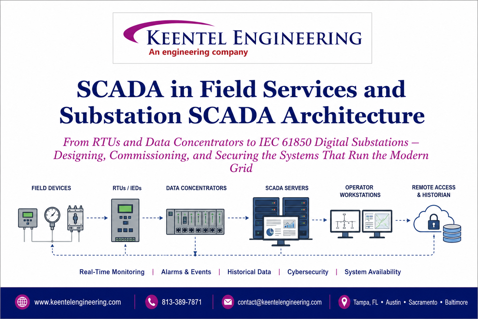
Learn SCADA architecture, IEC 61850, RTUs, IEDs, DNP3, digital substations, commissioning, cybersecurity, and field services for modern power systems.
By SANDIP R PATEL
•
July 13, 2026
Learn how IEEE standards for grounding, protection, power quality, arc flash, and grid interconnection are applied in real engineering projects.
By SANDIP R PATEL
•
July 12, 2026
Complete PRC-028-1 guide for inverter-based resources. 12-chapter technical resource
By SANDIP R PATEL
•
July 11, 2026
Learn modern data center design, grid interconnection, electrical systems, cooling, commissioning, resilience, and operations for AI-ready facilities.

By SANDIP R PATEL
•
July 11, 2026
Master IEC 61850 SCADA engineering with ACSELERATOR Architect, GOOSE messaging, MMS, SCL files, server models, commissioning, and substation automation.
By SANDIP R PATEL
•
July 11, 2026
Learn power system protection and relaying, SCADA integration, relay coordination, fault analysis, grounding, and substation protection engineering.


