
A Coordinated Electric System Interconnection Review—the utility’s deep-dive on technical and cost impacts of your project.
Challenge: Frequent false tripping using conventional electromechanical relays
Solution: SEL-487E integration with multi-terminal differential protection and dynamic inrush restraint
Result: 90% reduction in false trips, saving over $250,000 in downtime
ERCOT enforces all of the above through simulation, which means your model is your compliance case. The bar is now high:
- Whole-facility scope. The model must represent everything the IT load, the UPS and power conversion, the cooling plant, the protection and control systems in formats compatible with ERCOT's study platforms (PSS/E, PSCAD, TSAT).
- Real control loops, not approximations. Generic textbook representations are unacceptable. The model must capture the actual inner control behavior of your power electronics.
- Hardware-validated converter models. For electronic loads, the PSCAD model must be benchmarked against actual hardware testing including voltage ride-through and subsynchronous response. A model assembled from standard PSCAD library blocks fails by definition, because a generic block has never been tested against your vendor's hardware. The good news: validation is a hardware-type test, so results for a given converter product are reusable across every facility that uses it.
- Format migration. Facilities that previously submitted the older composite load model (CMLD) format must transition to EPRI's PERC1 format.
- Three checkpoints. Models are reviewed before the stability study begins (no model, no study), before each quarterly stability assessment, and for electronic loads one final time before energization, when you must submit as-built models with a documented comparison against the previously studied data and a sworn attestation that the model matches actual field settings. ERCOT's review takes 10 business days, extendable by 20 put it on your critical path.
- A living obligation. Change your technology, controls, or relay settings in a way that affects ride-through including converting a crypto mining site to an AI data center — and you've triggered a new interconnection study, even if your megawatts don't change.
| Parameter | Detail |
|---|---|
| System | 230 kV / 138 kV transmission corridors, wind and wet-snow icing exposure |
| Data basis | 15 years of minute-resolution forced-outage records + regional weather observations |
| Core methods | Event grouping, MVA performance curves, time-to-95%-restore, area outage rate curves, fragility modeling, rerun-history benefits, exceedance and log-domain risk metrics |
| Headline result | ≈85% of maximum resilience benefit at 60% of original capital; worst-event restoration window cut from 11 days to 5 in rerun-history terms |
| Decision supported | Capital portfolio selection; resilience plan filing; post-investment verification framework |
| System / Topic | Governing Standard(s) | What It Controls |
|---|---|---|
| Overall plant electrical distribution | IEEE 141 (Red Book); IEEE 666 | Distribution architecture, voltage selection, design of generating station auxiliary service systems |
| Power system studies | IEEE 399 (Brown Book); IEEE 551 | Load flow, symmetrical/asymmetrical short circuit, motor starting methodologies down to the lowest LV panelboard |
| Protection & coordination | IEEE 242 (Buff Book); IEEE 3004.5; IEEE C37 series | Generator relaying (21, 59N, 87G), time-current coordination, selective clearing between LV and MV tiers |
| GSU / UAT / SST transformers | IEEE C57.12.00 and C57 family | Transformer ratings, impedance, testing, loading |
| HV switchyard breakers | IEEE C37.06 | AC high-voltage circuit breaker preferred ratings |
| MV switchgear (13.8 kV) | IEEE C37.20.2; IEEE C37.20.7 | Metal-clad construction, compartmentalization, vacuum breakers; arc-resistant design with plenum venting |
| MV cable | UL 1072; ICEA S-93-639 (NEMA WC 74) | Type MV-105 shielded cable, 133% insulation level for HRG systems |
| LV switchgear (480 V) | IEEE C37.13; UL 1558 | Metal-enclosed LV power circuit breaker switchgear to 635 V, draw-out ACBs with electronic trip units |
| Motor control centers | UL 845; NEMA ICS 18 | LV-MCC construction, MCCB/MCP protection for motors under ~200 HP |
| Motors | NEMA MG-1 | Motor performance, starting characteristics, service factors |
| DC & battery systems | IEEE 485; IEEE 946 | Lead-acid battery sizing (125/250 VDC), DC auxiliary system design |
| Grounding | IEEE 80; IEEE 142 (Green Book) | Ground grid step/touch potential limits; system grounding including high-resistance grounding |
| Lightning protection | IEEE 998 | Direct-stroke shielding of switchyard and outdoor generator structures |
| Arc flash & electrical safety | IEEE 1584; NFPA 70E | Incident energy calculation; worker safety boundaries and PPE |
| Fire protection | NFPA 850 | Fire protection and risk management for combustion turbine generating plants |
| Installation code | NEC (NFPA 70); NESC | Wiring methods inside the plant fence; overhead/outdoor clearances at the switchyard |
| Interconnection & compliance | FERC LGIP; NERC MOD-025/026/027, PRC-019/024/029, FAC-008 | Interconnection process, model validation, protection/ride-through coordination, facility ratings |
| IFC / Construction Deliverable | Purpose |
|---|---|
| Stamped IFC packages | Legal basis for construction; P.E. responsible charge |
| Final relay settings & TCCs | Protection as-installed matches the coordination study |
| Calculation archive | Owner records; NERC audit evidence trail |
| Commissioning procedures | Safe, sequenced energization; MOD field testing |
| Construction support | RFIs, field changes, FAT/SAT witness |
| As-builts & model handoff | Operating baseline; future study currency |
| Metric | Outcome |
|---|---|
| Defects found pre-occupancy | Three topology defects and one settings-mismatch family corrected before load migration; the shared-switchboard defect alone would have invalidated the concurrently-maintainable claim on day one |
| IST findings | Fourteen additional discrepancies surfaced under scenario testing (control logic, alarm mapping, one generator sequencing fault) — all closed before handover instead of during operations |
| Black-building test | Passed on second execution; the first attempt exposed the generator sequencing fault under true block load, exactly the failure the compressed plan would never have found |
| Handover quality | Operations team certified on the actual failure scenarios; corrected EOPs and settings documentation delivered as controlled documents |
| Business outcome | Occupancy proceeded three weeks behind the original date — against an independent estimate that the uncorrected sequencing fault carried a high probability of a full facility outage within the first year |
Part 2 — Frequently Asked Questions: Large Load Interconnection
An electric grid must remain in continuous balance — generation onto the grid must equal consumption from it at every instant. PJM achieves this balance, and prices it, through a layered market architecture. Each layer operates on a different time horizon, and each one touches project economics differently.
| Domain | Key Standards / Codes | What They Govern |
|---|---|---|
| Fire safety | NFPA 855; UL 9540 / UL 9540A | Installation requirements, separation, gas management; system safety listing and thermal-runaway fire testing |
| Grid interconnection | IEEE 1547 (distribution); IEEE 2800 (transmission IBRs) | Ride-through, reactive capability, power quality, and performance at the point of interconnection |
| Power quality | IEEE 519 | Harmonic distortion limits at the PCC |
| Protection & grounding | IEEE 80 / 81 / 142; C37 series | Grounding system design and testing; protective relaying |
| Reliability compliance | NERC standards (incl. PRC ride-through requirements) | Registered-entity obligations for grid-connected storage |
The Substation Inspection Checklist, Rewritten as Engineering: What Sits Behind Every Checkbox
Aug 15, 2026 | Blog
A Keentel Engineering Grid IQ technical guide for owner's engineers, QA/QC managers, commissioning leads, and generator owners
Introduction: The Checklist Is the Easy Part
A good substation inspection checklist fits on one page. It has ten or so sections — documents, materials, cable, earthing, installation, connections, testing, protection, labeling, safety — and under each, five or six lines with a box beside them. "Earth continuity & resistance test." "Terminal tightness & identification." "CT / PT ratio & polarity check." "Cable size & type as per drawing."
Every one of those lines is defensible. Together they are a genuinely useful memory aid, and the mindset that usually accompanies them — see it, check it, verify it, record it, report it, follow up — is the right instinct.
The problem is that a checkbox is a binary, and almost nothing on that list is binary.
"Earth continuity & resistance test" is not a pass/fail against a number. It is a question about whether the measured grid impedance, combined with the actual available fault current and clearing time, keeps computed step and touch potentials below tolerable limits for the surfacing that was actually installed — and IEEE 80 does not contain the "one ohm" figure most inspectors are looking for. "Terminal tightness" is not a matter of whether the bolt feels tight; it is a matter of whether the connection was made once, correctly, with a calibrated tool, to the manufacturer's value — and whether a connection that needed re-tightening should have been re-worked instead. "CT ratio & polarity" passes routinely on a bench and still lets a swapped lead through, because only primary injection proves the whole current path.
This guide takes the standard ten-section inspection checklist and rewrites it as engineering: what standard governs each line, what the acceptance criterion actually is, what the failure data says about which items matter most, and where the industry's own published evidence is thinner than people assume.
It is written for the person who has to sign the turnover package.

Part 1 — The Framework the Checklist Implies but Never Names
1.1 Quality assurance and quality control are not synonyms, and the distinction is contractual
The cleanest, freely citable definitions in US practice come from the US Army Corps of Engineers' construction quality management regulation, ER 1180-1-6 (March 2025):
- Contractor Quality Control (CQC) — "the construction contractor's system to manage, control, and document their own, their supplier's, and their subcontractor's activities to comply with contract requirements."
- Quality Assurance (QA) — "the system by which the Government fulfills its responsibility to be certain the CQC functions effectively and the end product complies with the specified requirements."
Map that onto substation work and the roles resolve immediately: the contractor's testing organization performs the test; the owner's engineer verifies that the testing system produces trustworthy results and audits the records. An owner's engineer who spends their day re-performing the contractor's tests has misunderstood the assignment. An owner's engineer who accepts a stack of test sheets without ever witnessing a test, checking a calibration certificate, or tracing a result back to a setting file has also misunderstood it.
USACE also supplies the most useful structural idea in construction QA, and one that maps far better to substation work than a flat checklist does: the Three Phases of Control, applied to each definable feature of work:
- Preparatory — before work starts: review the requirements, inspect the site and materials, hold a preparatory meeting.
- Initial — inspect a representative first sample, establish the workmanship standard everyone will be held to, verify the safety plan.
- Follow-up — continuous inspection of ongoing work against the standard set in the initial phase.
The regulation is blunt about a failure mode we see constantly: definable features of work "should be well thought out by QC for the specific contract and NOT a list of technical specifications." A checklist that is just the spec section headings re-typed is not a quality plan.
1.2 A precision point worth making: hold points are not a standard
Search for an ANSI, ISO, or IEEE definition of "Inspection and Test Plan," "Hold Point," "Witness Point," "Review Point" or "Surveillance Point" and you will not find one. These are contractual and industry-convention terms, not standardized ones. The usual definitions — H means work cannot proceed without sign-off; W means notify the inspector, who may or may not attend; R means document review; S means unannounced surveillance — are conventions that a great many organizations share, not requirements anyone can cite you to.
This matters practically. Because there is no standard behind them, the ITP is only as strong as the contract that incorporates it. If the specification does not state that a hold point stops the work, that the notification period is (say) 48 hours, and what happens when the inspector does not attend a witness point, then the letters in the column are decoration. We have seen more disputes arise from an undefined witness-point notification protocol than from any technical disagreement.
The ISO 9001:2015 hook that does exist is Clause 8.6, which requires that product "shall not be released until the planned arrangements have been satisfactorily completed." That is the standards basis for a hold point — but you have to write it into the contract yourself.
1.3 A non-conformance is not a punch item
This is the single most consequential process distinction in substation commissioning, and it is routinely collapsed.
A punch item is incomplete or cosmetically deficient work identified at substantial completion that does not affect function or safety — a missing warning label, touch-up paint, a cable tray cover not fitted.
A non-conformance is a documented departure from a specified requirement. Under ISO 9001:2015 Clause 8.7, it requires a formal disposition — correct, segregate, reject, or obtain authorization for a concession (accept-as-is) — and under Clause 10.2 it requires evaluating the cause so it does not recur.
The rule we apply: findings on protection settings, grounding, torque, or test results are never punch items. They are non-conformances, because they require causal analysis and re-verification rather than mere completion. A relay whose as-left settings do not match the approved setting file is not a snag; it is evidence that the settings management process failed, and the correct question is how many other relays are affected.
One more note on terminology, because it appears in a lot of specifications written by people who assume it is codified: ISO 9001:2015 removed "preventive action" as a standalone clause, folding it into the risk-based thinking of Clause 6.1. "CAPA" is an FDA/pharmaceutical construct (21 CFR 820.100), not an ISO 9001 one. Use it if your client's system uses it; do not cite ISO 9001 as its source.
1.4 FAT and SAT are also not standards terms
IEC 62271-1 defines type tests (design verification, performed once on a representative unit) and routine tests (performed on every unit in the factory). It does not define "Factory Acceptance Test" or "Site Acceptance Test." Neither does any IEEE standard we could locate.
FAT and SAT are contractual constructs layered on top of routine tests, and their scope is whatever your specification says it is. This is why FAT scope disputes are so common: two parties each assume "FAT" means the industry-standard thing, and there is no industry-standard thing.
What is standardized is the field side. ANSI/NETA ATS-2025, Standard for Acceptance Testing Specifications for Electrical Power Equipment and Systems — the current edition, ANSI-approved 20 February 2025, superseding ATS-2021 — specifies "field tests and inspections to assess the suitability for initial energization and final acceptance of electrical power equipment and systems." The 2025 edition added Section 7.28 for battery energy storage systems and 7.29 for solar PV, expanded the medium-voltage cable acceptance table with subcategories by cable type and test method, and added a new appendix on selecting cable test methods by circuit reliability requirements.
Its companion, ANSI/NETA ECS-2024 (Standard for Electrical Commissioning Specifications, third edition, ANSI-approved 2 July 2024), operates at the system level: verification that installed systems are operational, within standards and manufacturer tolerances, and installed in accordance with design specifications — plus integrated system performance verification and baseline data for later trending. In practice ECS wraps ATS: ATS results become an input to the commissioning record, and ECS adds design-intent verification, functional testing, and turnover documentation.
The practical takeaway for a specification writer: cite ATS-2025 for equipment acceptance, cite ECS-2024 for system commissioning, and define FAT/SAT scope yourself in words rather than assuming a shared meaning.
1.5 What FAT data must travel to site
Whatever you call it, the factory test record's real purpose is to become the baseline against which every site result is compared. FM Global's guidance makes the point directly for transformers: power factor testing "is most effective when results are compared to installation acceptance tests and/or recommended manufacturer values."
At minimum, the factory record that follows the unit to site should contain, per unit and per phase:
- Turns ratio at every tap, with the calculated ratio alongside
- Winding resistance per winding, per phase, per tap, with the reference temperature stated
- Excitation current at each tap
- Power factor / capacitance for each insulation path and for each bushing individually (C1 and C2, with nameplate values)
- SFRA traces as the fingerprint baseline
- Insulation resistance with test voltage and temperature
- CT ratio, polarity, winding resistance, and the full excitation curve for every tap of every CT
If a site test cannot be compared to a factory value corrected to the same temperature, it is a number, not a result.
Part 2 — The Ten Sections, Rewritten
Section 1 — Document and drawing verification
The checklist asks for approved drawings and revision status, single-line diagrams, layouts, general arrangements, cable and earthing drawings, bill of quantities and datasheets, as-built versus approved drawing match, and the method statement, ITP and QCP.
What actually goes wrong here is revision control, not availability. The drawings are almost always on site. The question is whether the revision in the field matches the revision in the document management system, and whether the construction sequence has outrun the design.
The two checks that repay the most effort:
- Trace one circuit end to end across document types. Take a single protection function and follow it from the single-line diagram, to the three-line, to the AC and DC schematics, to the panel wiring diagram, to the cable schedule, to the interconnection drawing. Discrepancies between document types are far more common than errors within one.
- Verify that the setting file, the relay configuration, and the schematic tell the same story. This is the single highest-yield document check in a substation, and Part 4 explains why.
There is a documented case behind the first point. NERC Lesson Learned 20150401 describes two redundant remedial action scheme I/O devices that failed on firmware errors — with the failure alarms never reaching operators, because "the wiring diagram of the RAS panel did not match the schematic." The elementary schematic was correct. The panel wiring was not. Positive DC had never been connected to the alarm circuit. It was found during a post-event investigation, not during commissioning. The recommendation is worth adopting verbatim: status indications and alarms "should be verified by actuating device outputs" while monitoring at both local and remote locations, with formal individual alarm sign-offs at each.
As-builts. There is no authoritative standard defining as-built or red-line practice or turnover package contents for substations. The nearest citable hooks are ISO 9001 Clause 7.5 on documented information and USACE's requirement that contractors maintain "procedures for tracking construction deficiencies to validate acceptable corrective action and that an audit trail is maintained." Everything else is owner specification. Write it explicitly.
Section 2 — Material and equipment verification
Make, model and serial number; nameplate data against specification; factory test reports; calibration certificates; visual damage check.
Two items on this list carry disproportionate weight:
Calibration certificates. ISO 9001 Clause 7.1.5.2 covers measurement traceability, and it applies to your instruments as much as to the contractor's. A torque wrench, a micro-ohmmeter, a hipot set, a relay test set and an infrared camera are all measuring devices whose results you are about to certify. Torque tools in particular require periodic recalibration, and a torque record produced with an uncalibrated wrench is not evidence of anything. Check certificate dates against the test dates, not against the inspection date.
Serial number verification against the factory test report. This sounds pedantic until the day the report in the O&M binder belongs to a sister unit. On multi-unit orders it happens more often than anyone likes to admit, and it silently invalidates every subsequent comparison-to-baseline.
Damage inspection on arrival deserves more than a walk-around. For large transformers, the impact recorder trace and the shipping-brace condition are the meaningful evidence, and an SFRA test performed on arrival — before the unit is set — is the only practical field method for detecting winding displacement in transit. IEEE C57.149-2024 governs SFRA and supersedes the 2012 edition that most specifications still cite.
Section 3 — Cable and wiring checks
Cable size and type as per drawing; routing and identification; glands, lugs and termination; dressing, clamping and support; spare length and tagging.
The checklist item that hides the most engineering is "cable routing." Three limits govern whether an installed cable is still the cable that was specified:
- Pulling tension — conductor stress limits of 0.008 lb/cmil for soft copper and hard-drawn aluminium, and 0.006 lb/cmil for 3/4-hard aluminium and AA-8000 alloy; capped by hardware, conventionally the lesser of the pulling eye's rating or 10,000 lb, and about 1,000 lb for a basket grip.
- Sidewall bearing pressure — commonly 500 lb/ft for 600 V to 15 kV non-shielded power cable and 300 lb/ft for 25–35 kV cable and for interlocked-armour cable at all voltages, computed as tension out of the bend divided by bend radius in feet.
- Minimum bending radius — for shielded conductors over 600 V, the greater of 12× the individual shielded-conductor diameter or 7× the overall cable diameter; 8× overall diameter for non-shielded over 600 V.
These derive from ICEA G5-90 and the ICEA/AEIC installation literature, with NEC Article 300 and NETA's bending-radius table also applicable. NECA/NEIS 600 is the ANSI-approved workmanship standard for installing and maintaining medium-voltage cable.
The inspection point that follows is uncomfortable but correct: pulling tension and sidewall pressure are only verifiable while the pull is happening. A dynamometer chart from the pull, retained in the record, is real evidence. A checkbox ticked after the cable is in the duct is not. If the specification does not require pull tension recording, the "cable routing" line on the checklist cannot be meaningfully verified at all — and that is worth saying to the client before the cable goes in rather than after.
Termination carries its own hazard. Cable terminations and joints are the highest-defect-density elements of a medium-voltage cable system, and workmanship there is not verifiable by inspection after the fact. This is the strongest argument for partial discharge testing at commissioning — IEEE 400.3-2022 for field PD diagnostic testing, with IEC 60270 as the reference method for quantitative apparent-charge measurement in picocoulombs.
Section 4 — Earthing and bonding checks
Earthing system as per drawing; earth pit, electrode and backfill; earth continuity and resistance test; bonding of all equipment and structure; equipotential bonding.
This is the section where the checklist most badly misrepresents the engineering.
The governing document is IEEE Std 80-2013, Guide for Safety in AC Substation Grounding. Its acceptance criteria are step voltage and touch voltage limits, computed from tolerable body current, fault-clearing time, soil resistivity, and the surface layer material — not grid resistance. The widely quoted "≤ 1 Ω for substations, ≤ 5 Ω for distribution" figures are rules of thumb that appear nowhere in IEEE 80 as requirements.
They are also misleading in both directions. A 0.5 Ω grid in high-resistivity soil, with a large ground potential rise and no crushed-rock surfacing, can fail touch-voltage criteria. A 5 Ω grid with modest fault current, fast clearing, and a properly specified surface layer can pass comfortably.
The correct inspection question is therefore: does the measured grid impedance, combined with the actual available fault current and the actual clearing time, keep computed step and touch potentials below IEEE 80 tolerable limits for the surfacing that was installed — and does the measured impedance match the design model within an agreed tolerance?
Two measurement issues follow:
Fall-of-potential and the 61.8% rule. IEEE Std 81 — now in its 2025 edition, with the widely cited 81-2012 moved to Inactive-Reserved in March 2023 — describes injecting current between the grid and a remote current electrode and traversing a potential probe along the line between them. The 61.8% placement rule derives from a uniform-soil, hemispherical-electrode idealization. A real substation grid violates every one of those assumptions: it is large, it is not hemispherical, the soil is layered, and buried metallic infrastructure couples the electrodes. Correct practice is to plot the full traverse and look for a flat plateau; if no plateau appears, the current electrode is too close. The working rule is that the remote electrode belongs at five to ten times the maximum grid diagonal, which for a large station means test leads measured in hundreds of metres. Where that is impossible, IEEE 81 provides the slope and intersecting-curves methods.
Soil resistivity. The Wenner four-pin method with electrodes at spacing a gives apparent resistivity ρ = 2πaR. Varying a probes progressively deeper strata, and the resulting curve is inverted into a layered soil model that feeds the IEEE 80 design. A grounding design based on a single-spacing resistivity measurement is a legitimate non-conformance, because a single spacing cannot resolve a layered model, and the layered model is what determines the design.
Connections. IEEE Std 837-2024 (superseding 837-2014) governs the qualification of permanent connections used in substation grounding — connectors are subjected to sequential electromagnetic, freeze-thaw, corrosion and fault-current testing. It is a product qualification standard, not a field test method. The field verification is continuity, connection type against the approved detail, and — for exothermic welds — visual inspection against the manufacturer's acceptance photographs before backfill.
The consequence of getting this wrong is documented. NERC Lesson Learned 20200402 describes a single-phase-to-ground fault on a CCVT that persisted over four minutes without primary or backup clearing. Among the contributing causes: post-event testing found inadequate continuity between adjacent ground grids, allowing a more severe transient; DC supply ran roughly 1,000 feet in shared trenches with AC control wiring, coupling the transient into the 125 VDC supply; and all eight internal power supplies across four communications multiplexers shut down simultaneously, blocking the line differential relay from tripping.
Section 5 — Panel and equipment installation
Switchgear and transformer installation; clearances and working space; mechanical fixing and alignment; painting, coating and finish; nameplate and warning signs.
Clearances are where the jurisdictional question bites, and it is worth resolving before the first inspection rather than during a dispute.
NEC 90.2(B) excludes installations under the exclusive control of an electric utility for the purpose of generation, transmission and distribution. Utility substations are therefore governed by the NESC (IEEE C2), not the NEC. Generator-owner and industrial substations behind the meter generally fall under the NEC plus NFPA 70E. The current editions are IEEE C2-2023 (with C2-2028 in the change-proposal cycle) and NFPA 70-2026.
Getting this boundary right determines which clearance table applies, which working-space dimensions apply, and which safety standard governs the work itself. It is a routine owner's-engineer dispute and it is entirely avoidable by stating the applicable code in the specification.
The other standards an installation inspection verifies against, all recently revised and all commonly cited in stale editions:
| Subject | Current standard |
|---|---|
| Bus design in air-insulated substations | IEEE 605-2023 (supersedes 605-2008/2011) |
| Seismic design of substations | IEEE 693-2018 |
| Direct lightning stroke shielding | IEEE 998 — the 2012 edition moved to Inactive-Reserved in March 2023; confirm the current revision status before citing |
| Environmental and community design | IEEE 1127-2023 (supersedes 1127-2013) |
| Substation grounding | IEEE 80-2013 |
| Workmanship in electrical construction | NECA 1 |
Painting and coating is not a cosmetic line. In coastal, industrial and desert environments the coating system is the asset's corrosion protection, and the meaningful verification is dry film thickness measurement against the specified system, surface preparation records, and holiday detection where specified — not a visual check.
Section 6 — Circuit and connection checks
Control circuit; auxiliary circuit; power circuit; terminal tightness and identification; ferruling and insulation check.
"Terminal tightness" deserves to be rewritten entirely, because the industry's own guidance says something stronger than the checklist does.
The hierarchy of authority for bolted electrical connections is unambiguous:
- The manufacturer's published torque data governs. NETA states it explicitly: bolt-torque levels shall be in accordance with manufacturer's published data.
- In the absence of manufacturer data, NETA's torque table is the fallback — subdivided by fastener material, because silicon bronze, aluminium alloy and stainless values are substantially lower than heat-treated steel and must never be substituted for one another. The table does not cover metric hardware, which matters on IEC-sourced GIS and transformers.
- IEEE 837 governs qualification of permanent grounding connections, not their field torque.
Then there is the point that changes how you inspect. FM Global's electrical testing data sheet states: "When properly made, an electrical connection should not require retightening" — and notes that most switchgear manufacturers advise that connections requiring re-tightening be entirely reworked.
Read that carefully. Re-torquing is not maintenance; it is evidence that the connection was defective. A maintenance program built on annual re-torquing is a program that has normalized a defect. The correct inspection posture at construction is to verify that the connection was made once, correctly, with a calibrated tool, by a person who recorded it — and to treat a loose connection found later as a non-conformance requiring rework, not a tightening opportunity.
Aluminium joints add a further requirement that no torque figure captures. Aluminium's thermal expansion and tendency to cold-flow under sustained load cause a rigid bolted joint to lose clamping force over thermal cycles — the classic origin of rising joint resistance and thermographic hot spots. Belleville washers maintain clamp load through that creep, installed one per bolt with a flat washer between the Belleville and the aluminium, and torqued per the washer or connector manufacturer's instruction rather than a generic figure. A Belleville flattened solid has lost its spring function. Aluminium also requires wire-brushing through the oxide under an oxide-inhibiting compound, mated before the oxide re-forms. These are manufacturer instructions, not NETA or IEEE clauses — cite them as such.
Connection resistance measurement is the objective check that "tightness" is not. The NETA criterion for bolted connections is to compare resistance values to those of similar connections and investigate values deviating by more than 50 percent of the lowest value. The reference is the lowest value in the comparison set, not the average — for poles reading 45, 48 and 70 µΩ, the threshold is 45 × 1.5 = 67.5 µΩ, so the 70 µΩ pole is investigable. FM Global states the same 50 percent criterion. Note that this is a trigger for investigation, not automatic rejection, and manufacturer data takes precedence wherever it exists.
Control and auxiliary circuits are not a lesser category. Section 4 of this guide explains why: the CIGRE circuit breaker survey data indicates that mechanism and control/auxiliary circuit problems, not interrupters, dominate breaker failures.
Section 7 — Testing and commissioning checks
Insulation resistance
HV/AC withstand; contact resistance; secondary injection; relay and protection test; functional test local/remote; instrument calibration; FAT data review and match.
This is the section with the most standards behind it and the most stale citations in circulation.
Insulation resistance. For apparatus other than rotating machinery, the governing field-test document is IEEE C57.152-2025 — note that C57.152-2013, which most specifications cite, moved to Inactive-Reserved in March 2024, and that IEEE 62-1995 was superseded by C57.152 long before that. NETA provides the acceptance table by equipment voltage rating, with the required test voltage alongside; check the values against the current ATS edition rather than a reproduction, because the commonly circulated tables differ between editions and secondary sources disagree on several rows.
Two derived quantities matter more than the raw value:
- Polarization Index (PI) = insulation resistance at 10 minutes ÷ resistance at 1 minute. NETA acceptance: not less than 2.0.
- Dielectric Absorption Ratio (DAR) = resistance at 60 seconds ÷ resistance at 30 seconds. NETA acceptance: not less than 1.4.
Two cautions that separate a useful result from a meaningless one. PI is not meaningful when the one-minute resistance exceeds about 5,000 MΩ — measurement noise dominates and the ratio becomes unreliable, which is why a modern dry-type unit can produce an alarming PI while being perfectly sound. And insulation resistance must be corrected to a reference temperature (40 °C for machines) before comparison; PI itself needs no correction because the factor cancels, but only if winding temperature is stable across the ten minutes.
For rotating machinery, IEEE Std 43 sets minimum values that vary by construction era, and it contains a genuine trap: applying the legacy kV + 1 MΩ formula to a modern form-wound stator gives roughly a twentieth of the actual 100 MΩ requirement. Note also that IEEE 43-2013 moved to Inactive-Reserved in March 2024 with a revision project active — another standard most specifications still cite as current.
Transformer testing
Turns ratio must be within ±0.5% of the calculated ratio per IEEE C57.12.00-2021, on all taps, with phase relationship and vector group verified. Winding resistance is measured per winding, per phase, per tap, corrected to a common temperature, and interpreted comparatively — against phases and against the factory report at the same temperature — rather than against a universal limit. Power factor and capacitance are measured in GST, GSTg and UST configurations to isolate the CH, CL and CHL insulation paths, corrected to 20 °C, with bushings evaluated individually against nameplate C1 power factor and capacitance. Excitation current on a three-legged core-form unit should show the characteristic pattern of two similar higher readings on the outer phases and a lower centre-phase reading; departure from that pattern indicates shorted turns, core problems or tap-changer issues.
Dissolved gas analysis is governed by IEEE C57.104-2019, which replaced the older Condition 1–4 and total-dissolved-combustible-gas scheme with a percentile-based Status 1/2/3 framework, stratified by transformer age and by oxygen-to-nitrogen ratio. TDCG was removed as a primary diagnostic parameter, and Duval Triangle and Pentagon methods are the primary fault-typing tools with Rogers Ratios and Key Gas relegated to supplementary status. Because the thresholds are age- and O₂/N₂-conditional, single-column "DGA limit" tables circulating online are not usable — take the values from the standard.
Cable testing. The entire IEEE 400 series has moved, and this is the most common stale-citation cluster we encounter:
| Standard | Current edition |
|---|---|
| IEEE 400 — field testing and evaluation of shielded power cable insulation, 5 kV and above | 400-2023 |
| IEEE 400.1 — HVDC testing of laminated dielectric cable systems | 400.1-2018 |
| IEEE 400.2 — very low frequency (VLF) testing | 400.2-2024 |
| IEEE 400.3 — partial discharge field diagnostic testing | 400.3-2022 |
Two substantive points, not just currency:
IEEE 400.1 covers laminated dielectric only — PILC, lead-covered, pipe-type, pressurized. It does not cover extruded XLPE or EPR. Citing 400.1 as the authority for DC hipotting an XLPE feeder is a scope error.
DC hipot is discouraged for aged extruded cable for a physical reason worth understanding. DC stress traps charge carriers in the polymer, creating localized field intensification that can persist for weeks; on de-energization or polarity reversal, that trapped charge can drive breakdown at voltages the cable withstood during the test. On service-aged cable, DC stress can also convert benign water trees into electrical trees — meaning the test itself creates the defect. This is the origin of the well-documented "passed the test, failed the next week" pattern that drove the industry toward VLF, PD and damped-AC methods. (A frequently circulated quote attributing a five-year rule to a specific NETA clause appears only on low-quality aggregator sites and could not be verified against the NETA document; do not repeat it.)
Circuit breakers
Timing per pole and pole-scatter, trip and close coil current signatures, minimum pickup voltage of trip and close coils, contact resistance, insulation resistance pole-to-pole, pole-to-ground and across open contacts. Manufacturer data governs the limits; NETA defers to it. For SF₆ equipment, IEEE C37.122.3-2024 (superseding the 2011 edition most specifications cite) covers gas handling, with new technical-grade gas nominally at ≥99.7% purity and moisture around 25 mg/kg — roughly a −36 °C dew point at 100 kPa and 20 °C — and closed-pressure system leakage below 0.5% per annum per gas compartment. Note that mg/kg, ppmv and ppmw are routinely conflated in field reports, and a dew point specification is meaningless without the pressure stated.
Vacuum interrupters deserve a specific caution: no insulation resistance test proves vacuum integrity. The accepted methods are an AC or DC withstand test across open contacts at the manufacturer's specified value, or a dedicated magnetron-type vacuum bottle tester. DC testing across open vacuum contacts produces X-radiation — observe the manufacturer's standoff distance and voltage cap.
Instrument transformers
IEEE C57.13-2016 governs, with C57.13.1 for field testing of relaying CTs. Field acceptance covers ratio at all taps, polarity, excitation/saturation curve, winding resistance, burden and insulation.
The one thing worth internalizing: relaying accuracy class notation is a burden capability statement, not a percentage. All ANSI relaying classes require ratio error not exceeding ±10% from 1× to 20× rated secondary current at the stated burden. The numeric suffix is the secondary terminal voltage the CT delivers at 20× rated secondary current without exceeding that error — so a C400 CT delivers 400 V at 100 A, meaning a 4 Ω burden capability. The letter matters too: C means the error can be calculated from the excitation curve, T means it must be determined by test, and K adds a guaranteed knee-point at not less than 70% of the secondary terminal voltage rating.
And do not interchange knee points. The ANSI 45° knee — the point on the log-log excitation curve where the tangent makes 45° with the abscissa — and the IEC knee — a 50% voltage increase producing a 10% current increase — are different, and the IEC point is higher. Substituting one for the other in a relay setting review is a real and recurring error.
Section 8 — Protection and control checks
Relay setting verification; CT/PT ratio and polarity; interlocking and logic; trip circuit continuity; alarm and indication.
IEEE C37.233-2023, Guide for Power System Protection Testing, is the current edition and supersedes the 2009 version that nearly every specification in circulation still cites. It covers the full lifecycle: design and model verification, factory acceptance, field commissioning, in-service and periodic testing, and post-fault analysis.
The test hierarchy an owner's engineer should expect to see, and the specific defect each layer catches:
- Secondary injection — per-element pickup, dropout, timing and characteristic verification at the relay terminals. Catches: settings that do not match the approved setting file.
- Primary injection — proves the whole current path from CT primary through secondary wiring to the relay input, including ratio, polarity and burden as installed. Catches: a swapped CT lead, a shorting screw left in, a wiring error between the CT and the panel. Nothing else catches these.**
- Functional trip check, point to point — every relay output contact actually trips the intended breakers and lockout, through all interposing auxiliaries, by actual breaker operation rather than by jumpering. Catches: wiring errors downstream of the relay, and loose connections in auxiliary relay coil circuits.
- End-to-end testing — GPS-synchronized simultaneous injection at both line terminals, proving line differential and pilot schemes plus the communications channel under realistic fault timing. Catches: channel logic and coordination errors invisible to single-ended testing.
- System function tests — ANSI/NETA ATS Section 8 — integrated verification of interlocks, transfer schemes and SCADA point-to-point.
Item 3 is where the checklist item "trip circuit continuity" quietly under-specifies. NERC Lesson Learned 20150902 describes a single-phase-to-ground fault on a 230 kV three-terminal feeder that evolved into a multi-phase fault lasting 58 seconds, despite fully redundant protection, because two independent relay failures prevented local breaker trips after reclosing. The root cause on one line relay: "a loose connection in the trip auxiliary relay coil cutoff contact string was identified, preventing coil energization." Breaker failure protection never initiated, because it depended on the same failed auxiliary relays. Backup ground protection on distant 500 kV lines eventually cleared it.
The recommendation is directly quotable and belongs in every commissioning specification: "Inclusion of breaker trip testing in conjunction with relay testing may result in a greater probability of identifying loose connections." Alongside it: connect trip contacts directly to breakers independent of auxiliary relays where practicable, use separate contacts for breaker-failure initiation, and verify that actual breaker trips occur during functional testing, not merely that the relay output asserts.
One structural recommendation for NERC-jurisdictional facilities: structure the commissioning record so it can serve as the first PRC-005 maintenance record. PRC-005-6 sets maximum intervals for time-based programs — unmonitored protective relays at 6 calendar years, unmonitored voltage and current sensing devices at 12 calendar years, unmonitored trip coils and electromechanical lockout devices at 6 calendar years, with station DC supply on a 4-calendar-month inspection cycle and battery performance requirements varying by chemistry. Commissioning establishes the baseline; PRC-005 governs the recurrence. Building the record in the wrong format means re-creating it later.
Section 9 — Labeling, documentation and QC
Equipment tagging and labeling; document handover check; test report compilation; punch and defect list follow-up; photographic record.
Labeling is treated as trivial and is not. A mislabeled cable or panel is a latent safety defect that surfaces during an emergency switching operation, when nobody has time to verify it against a drawing. Verification means matching the label to the cable schedule and to the as-built, in both directions, and checking that ferrule numbering matches the schematic at both ends of every conductor.
Test report compilation is where the audit trail either exists or does not. A defensible report package contains, for every test: the instrument used and its calibration certificate date; the test date and the ambient conditions; the technician's name and certification level; the acceptance criterion applied and its source; the measured values; the comparison baseline; and the disposition. A report that gives only a value and a tick provides no basis for anyone to re-evaluate the result later — and later is exactly when it will be needed.
Photographic record matters most for work that becomes permanently invisible: exothermic ground connections before backfill, cable pulls before ducts are sealed, torque marks on bolted connections, foundation and conduit stub-ups before concrete. Set the requirement before the concrete pour, not after.
Section 10 — Safety and housekeeping
Safety signage and barricading; PPE compliance; fire extinguisher availability; housekeeping and cleanliness; access and egress.
The jurisdictional point from Section 5 recurs here and is more consequential. For utility-owned generation, transmission and distribution work, OSHA 29 CFR 1910.269 (operation and maintenance) and 29 CFR 1926 Subpart V (construction) are the enforceable federal rules — not NFPA 70E. NFPA 70E applies to industrial, commercial and generator-owner premises wiring. The current 70E edition is NFPA 70E-2024, with a 2027 edition in development.
The 2014 OSHA rule that harmonized 1910.269 and 1926 Subpart V introduced the electric power industry's first arc-flash requirements: employers must estimate incident energy and provide arc-rated clothing and PPE, and minimum approach distances are computed from maximum anticipated per-unit transient overvoltage rather than read from a fixed table. 1926.962 governs grounding for employee protection — protective grounds must be rated for the available fault current and placed to keep employees outside the fault-current path. Verifying that temporary protective grounding is rated for the actual available fault current, not simply present, is a real inspection item and a commonly skipped one.
There is also a maintenance-condition dependency worth flagging to owners. NFPA 70E requires equipment to be maintained, because incident-energy calculations assume the overcurrent device operates within its published characteristics. NFPA 70B — a Standard rather than a Recommended Practice since the 2023 edition, currently in its 2026 edition — supplies the maintenance framework, driving intervals from an Equipment Condition Assessment scored across physical condition, criticality and operating environment, with the worst of the three governing. Practically: a breaker whose condition of maintenance is unknown invalidates the arc-flash label on its enclosure.
Part 3 — "Important Data to Verify and Match"
The lower band of a good inspection checklist typically lists the data that must be consistent between the factory record, the drawings and the field: cable size and type, gland and packer size, earthing resistance value, separate drawing, separate circuit, testing data, nameplate data, calibration data, torque value, clearance and space.
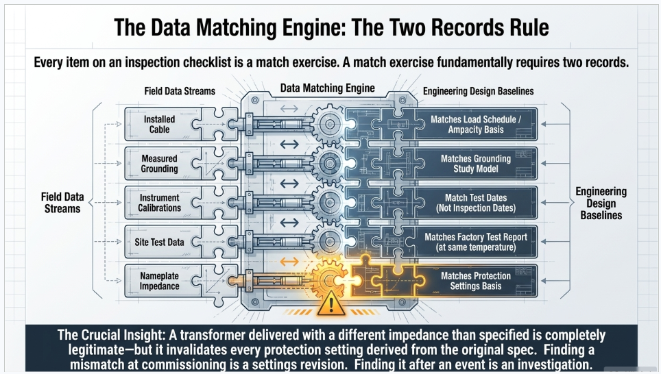
The unifying idea is worth stating plainly, because it is the whole discipline in one sentence: every item on that list is a match exercise, and a match exercise requires two records.
| Data item | Match against | The failure mode |
|---|---|---|
| Cable size and type | Cable schedule, cable sizing calculation, ampacity basis | Cable installed to schedule while the schedule was superseded by a load change |
| Gland / packer size | Gland schedule, cable OD, hazardous-area certification where applicable | Gland sized for the wrong OD compromises the seal, the shield bond and the ingress rating |
| Earthing resistance value | Grounding study model, actual fault current, actual clearing time, installed surfacing | Measured against a rule-of-thumb ohm figure instead of the design model |
| Separate drawing | Revision register | Field revision not the controlled revision |
| Separate circuit | Schematic, cable schedule, segregation requirements | AC and DC, or redundant protection groups, sharing a route or a multicore |
| Testing data | Factory test report at the same temperature | Comparison to nothing, or to a sister unit's report |
| Nameplate data | Purchase specification, datasheet, protection settings basis | Impedance or ratio differing from the value used in the setting calculations |
| Calibration data | Instrument certificates dated before the test date | Results produced with out-of-calibration tools |
| Torque value | Manufacturer's published data first, fallback table second | Generic figure applied to bronze, aluminium or metric hardware |
| Clearance and space | Applicable code — NESC or NEC, decided in advance | Wrong code applied to the installation type |
The most valuable of these is the seventh. The transformer or CT nameplate must be reconciled against the values used in the protection setting calculations. A unit delivered with an impedance different from the specification — well within manufacturing tolerance, entirely legitimate, and duly recorded on the nameplate — invalidates every setting derived from the specified value. Finding that at commissioning is a settings revision. Finding it after an event is an investigation.
Part 4 — What the Failure Data Actually SaysNew Paragraph
Inspection effort is finite. It should be allocated according to where equipment actually fails, and the published evidence is more specific — and in places more limited — than the industry usually admits.
4.1 Circuit breakers: it is the mechanism and the control circuit, not the interrupter
CIGRE's third international reliability enquiry on high-voltage equipment covered 281,090 three-phase circuit-breaker-years of single-pressure SF₆ breakers rated 60 kV and above over 2004–2007, recording 840 major failures and 6,655 minor failures — computed rates of roughly 0.30 and 2.37 per 100 circuit-breaker-years respectively.
The distribution matters more than the rate. An interim CIGRE working-group paper covering a large subset of that population attributed major failures as follows: operating mechanism and kinematic chain 52%, electrical control and auxiliary circuits 22%, component at service voltage 26%. Leading failure modes: does not close on command 29%, locked in open or closed position 19%, dielectric breakdown 15%, does not open on command 14%.
(These subassembly figures come from an interim paper on a subset, not the final brochure — treat the proportions as indicative rather than definitive.)
Roughly three-quarters of high-voltage breaker major failures originate in the mechanism and the control and auxiliary circuits. Those are precisely the items a commissioning plan tests: trip and close coil verification, minimum pickup voltage, auxiliary contact operation, mechanism travel and timing, and functional trip checks through the actual auxiliary relay chain.
CIGRE's fourth survey, covering 2014–2017 data, reported world-average major failure frequencies of about 0.99% for live-tank, 0.10% for dead-tank and 0.07% for GIS-type breakers, with an enormous spread between countries and CIGRE's own caveat that the results were still under evaluation.
4.2 Transformers: the rate is low, the consequence is not
CIGRE Technical Brochure 642 (WG A2.37) analysed 167,459 transformer-years from 58 utilities in 21 countries over 1996–2010 — a dataset roughly four times larger than earlier international surveys. Headline failure rates: approximately 0.53% per year for substation transformers and 0.95% per year for generator step-up transformers.
Windings were the largest single contributor to failure location in both applications; bushing-related failures increase with voltage class and carry the most severe external consequences — fire and explosion. Dielectric failure dominated the failure modes, with design and manufacturing, ageing and external short circuits identified as major contributors.
An important honesty note. TB 642 explicitly warns that because of the large proportion of "unknown" cases in the cause data, the cause results "should be treated and interpreted with caution." There is no CIGRE statistic quantifying the share of transformer failures attributable to installation workmanship. If you see one quoted, it has been invented. The same applies to substation equipment generally — no CIGRE, NERC, IEEE or EPRI publication we could locate quantifies the installation-workmanship share.
On bushings specifically, EPRI's 2023 transformer bushing failure investigation reports that bushings account for roughly 17–20% of overall transformer failures globally, and that approximately 30% of GSU transformer failures have been caused by a bushing malfunction. Its examination of four catastrophic failures among about 350 345 kV bushings at US nuclear facilities over two years identified manufacturing defects, electrical treeing, copper migration, paper degradation and voids, and mechanical conductor deformation — and lists bad workmanship, including improper joints and connections and improper transportation and handling, among the contributors, without quantifying its prevalence.
The practical inspection conclusion: individual bushing power factor and capacitance testing at acceptance, compared against nameplate C1 values, is disproportionately valuable relative to its cost.
4.3 Protection misoperations: a third are commissioning-controllable
NERC's 2026 State of Reliability reports 1,087 protection system misoperations against 18,397 protection system operations in 2025 — a misoperation rate of about 5.9%, and the lowest count over the preceding five years, with the metric trending as improving. NERC restates prior-year figures between editions, so always cite the report edition alongside the year.
NERC publishes the
cause distribution only as a chart. The best quantified public analysis is Oak Ridge National Laboratory's study of MIDAS data for 2016–2020, which gives the leading causes as:
| Cause | Share of reported misoperations |
|---|---|
| Incorrect settings | 23.45% |
| Relay failures / malfunctions | 18.87% |
| Communication failures | 10.64% |
| AC system | 10.17% |
| As-left personnel error | 10.06% |
ORNL also found that 95.5% of reported misoperations were unnecessary trips, and that line protection packages accounted for 58.2% of misoperations.
Here is the argument that follows, and it is the strongest available justification for a rigorous protection commissioning scope: incorrect settings (23.45%) plus as-left personnel error (10.06%) is roughly one third of all misoperations — and both categories are defects that a settings-review hold point and a witnessed end-to-end functional test are specifically designed to catch.
4.4 Connections and the insurer's view
The clearest quantified data on cause-of-loss comes from insurer claims rather than utility statistics. A Hartford Steam Boiler analysis of 94 transformer failures of 25 MVA and above over 1997–2001, totalling $286.6 million paid, distributed causes as follows: insulation failure 24 cases; design, material or workmanship 22 cases; unknown 15; loose connection 6; overloading 5; improper maintenance or operation 5; oil contamination 4; line surge 4; fire or explosion 3; lightning 3; flood 2; moisture 1.
Design/material/workmanship, loose connections and improper maintenance together account for 33 of 94 failures — about 35% by count and roughly 25% of claim dollars. That is the strongest defensible "human and manufacturing origin" figure available, with the caveat that the category conflates factory manufacturing defects with field workmanship.
FM Global's electrical testing guidance states the qualitative case plainly: "The majority of losses involving electrical equipment are related to poor operating conditions (e.g., overload, loose connections) or environment (e.g., poor ventilation, corrosion, contamination, combustible storage)." It recommends annual infrared thermography on all electrical equipment as "an excellent method for detecting improperly-made electrical connections," and reminds readers that for every 10 °C rise above rated operating temperature, a halving of insulation life can be expected.
4.5 The cost of finding it late
The Construction Industry Institute's research on rework provides the defensible economics: rework costs between 2% and 20% of a project's contract amount on a typical project, with CII benchmarking finding mean field rework in excess of 3% of construction-phase cost in heavy industrial projects, and earlier CII work estimating annual losses to rework in industrial construction at around $15 billion.
(The "1-10-100 rule" widely quoted in quality presentations has no traceable empirical source. It is a heuristic, and should not be presented as research. The CII figures do the same work and can be cited.)
For substation work specifically the asymmetry is sharper than a general rework multiplier suggests, because the defects that matter most are the ones that become inaccessible: a ground grid connection under backfill, a cable termination inside a completed switchgear cubicle, a conduit stub-up under a concrete pad. The cost differential is not a multiplier on labour; it is the difference between an hour of rework and an outage.
Part 5 — Your Specification Is Probably Citing Dead Standards
The most useful single finding from preparing this guide was not technical. It was that a large share of substation testing specifications in active US circulation cite standards that IEEE has since superseded or moved to Inactive-Reserved status.
"Inactive-Reserved" means IEEE no longer maintains the document. It remains purchasable and valid as historical reference, but it is not current practice — and specifying it obliges a contractor to test to a method the issuing body has stopped standing behind.
| Commonly cited | Actually current |
|---|---|
| ANSI/NETA ATS-2021 | ANSI/NETA ATS-2025 |
| ANSI/NETA ETT-2022 | ANSI/NETA ETT-2026 (approved 1 December 2025) |
| NFPA 70B-2023 | NFPA 70B-2026 (a Standard, not a Recommended Practice, since 2023) |
| NFPA 70-2023 (NEC) | NFPA 70-2026 |
| IEEE 43-2013 | Inactive-Reserved March 2024; revision project active |
| IEEE 62-1995 | Superseded — see C57.152 |
| IEEE C57.152-2013 | IEEE C57.152-2025 |
| IEEE C57.149-2012 | IEEE C57.149-2024 |
| IEEE 81-2012 | IEEE 81-2025 |
| IEEE 837-2014 | IEEE 837-2024 |
| IEEE 400-2012 | IEEE 400-2023 |
| IEEE 400.1-2007 | IEEE 400.1-2018 |
| IEEE 400.2-2013 | IEEE 400.2-2024 |
| IEEE 400.3-2006 | IEEE 400.3-2022 |
| IEEE 605-2008 / 605-2011 | IEEE 605-2023 |
| IEEE 1127-2013 | IEEE 1127-2023 |
| IEEE C37.233-2009 | IEEE C37.233-2023 |
| IEEE C37.122.3-2011 | IEEE C37.122.3-2024 |
| IEEE 3007.1 / 3007.2 / 3007.3 | All inactive — no successor. Cite NFPA 70B, NFPA 70E and ANSI/NETA MTS instead |
| ISO 19011:2018 | Withdrawn — superseded by a 2026 edition |
Two things follow. First, a standards currency review is a cheap, high-value scope item on any substation specification older than about three years — it takes days, not weeks, and it removes an entire class of contractual ambiguity. Second, if your specification cites a superseded edition, say so deliberately: "IEEE 400.2-2013 (superseded; retained for consistency with the existing fleet baseline)" is a defensible position. Citing it silently, because nobody checked, is not.
Part 6 — Which Standards Stack Applies
Substation inspection checklists circulate globally, and many of the ones in wide use carry a mix of references — IEC and IEEE, national utility regulations, and construction specifications — that do not all apply on any single project. The reference line on the graphic that prompted this guide lists IEC, IEEE, a national utility standard, a national construction specification, client specification, manufacturer manual and approved drawings. That is a reasonable hierarchy. What matters is knowing which stack you are in.
US utility transmission substation
NESC (IEEE C2-2023) for clearances, working space and approach distances → IEEE design standards (80, 605, 693, 998, 1127) → ANSI/NETA ATS-2025 and ECS-2024 for acceptance and commissioning → IEEE apparatus test standards (C57 and C37 series) → NERC standards where BES-jurisdictional (PRC-005, PRC-004, FAC series) → OSHA 1910.269 and 1926 Subpart V for the work itself → owner specification → manufacturer instructions. The NEC generally does not apply, per NEC 90.2(B).
US generator-owner or industrial substation behind the meter
NFPA 70 (NEC 2026) → NFPA 70E-2024 for work practices → NFPA 70B-2026 for maintenance → NETA ATS/ECS → IEEE apparatus standards → NERC where BES-jurisdictional → owner specification.
IEC-jurisdiction project
IEC 61936-1:2021 for installations above 1 kV AC (the closest IEC analogue to NESC and IEEE 80 combined, covering insulation coordination, clearances, safety distances, earthing, transformer installation, GIS, protection and verification) → IEC 60364 for LV auxiliary and station service, with IEC 60364-6 supplying the LV verification checklist → IEC 62271 series for switchgear → national utility regulations → national construction specification → client requirements.
A note on Middle East projects, since these checklists frequently originate there
In Qatar, for example, Kahramaa (Qatar General Electricity & Water Corporation) is both the utility and the approval authority — no installation is energized without its inspection and approval, and it issues its own HV/MV technical specifications and type-approval lists. QCS (Qatar Construction Specifications), published by the Public Works Authority and maintained through interim advice notes, is the national master construction specification incorporated by reference into public-sector contracts; it generally cross-references BS/EN/IEC standards rather than restating them. The practical hierarchy runs: utility regulations and type approvals (regulatory, non-negotiable) → national construction specification (contractual) → BS/EN/IEC (technical basis) → employer's requirements. Where a US owner's engineer imports NETA and IEEE test procedures into such a project, they sit on top of that stack as an additional owner requirement, not as a substitute — and any conflict resolves in the utility's favour. Because these regulations are typically built on BS 7671 and IEC 60364 conventions rather than the NEC, the resulting checklists read as IEC-flavoured even where a US EPC is executing.
Part 7 — Three Anonymized Case Studies
Confidentiality note
The three engagements below are presented in anonymized and generalized form. No client, utility, location, vendor or date is identified, and ratings, sequences and findings have been altered or aggregated. They are included to illustrate recurring engineering and process patterns, not to characterize any single project.
Case Study A — The Settings File That Nobody Owned
Situation. A greenfield transmission substation with multiple line terminals and a transformer bay was approaching energization. Protection commissioning had been performed by the contractor's testing subcontractor, and the test records were complete, legible and signed. The owner engaged us to perform an independent review of the commissioning package before energization.
What the review found
The secondary injection records demonstrated that each relay element performed as tested. What they did not demonstrate was that the settings tested were the settings that had been approved.
Tracing a sample of elements back through the document chain revealed that the setting files loaded in three relays corresponded to a revision that had been superseded during the design phase. The superseding revision changed a time-coordination margin on two elements following a fault-study update late in design. The change had been issued, reviewed and approved. It had never reached the field, because settings were being transmitted by email attachment and the field team was working from the copy they had received first.
Crucially, the test records were not wrong. Each relay had been tested faithfully against the file installed in it. The failure was in the settings management process, not in the testing.
Outcome and lessons
Three changes were made, and all three generalize:
- Settings became a controlled document with a hold point. No relay could be placed in service until the as-left setting file was verified — by file comparison, not by visual inspection — against the register revision, with the comparison recorded.
- The test record template was changed to require the setting file revision and checksum alongside the measured values. A test result that does not identify what was tested is not traceable.
- The finding was raised as a non-conformance, not a punch item, which triggered a causal review across all relays on the project rather than a fix to the three that had been sampled. Two further relays were found.
The wider lesson is the one from Section 8: a settings error is the largest single identified cause of protection misoperations in the published data. It is also invisible to every test in the standard commissioning sequence except a settings comparison, because secondary injection validates the relay against whatever is loaded in it.
Case Study B — The Ground Grid That Met Its Number and Failed Its Design
Situation. A substation expansion added a new bay and an extension to the existing ground grid. The construction specification called for a measured grid resistance below a stated ohmic value. The contractor measured it, achieved it comfortably, and submitted the result. Our scope included verification of the grounding installation against the design.
What the review found
The measurement was competently made and the value was genuine. It was also close to irrelevant to the question the specification should have been asking.
Three findings emerged:
- The soil resistivity data underpinning the design came from a single electrode spacing. A single spacing cannot resolve a layered soil model, and the layered model is what determines current distribution and therefore surface potentials. The design had assumed uniform soil.
- The fall-of-potential traverse showed no plateau. The remote current electrode had been placed at a distance dictated by the available land, not by the grid geometry — well short of the five-to-ten-times-diagonal working rule. The single-point reading at the conventional 61.8% position was therefore not a measurement of the grid's resistance; it was a measurement of the test setup.
- Continuity between the new grid extension and the existing grid relied on a smaller number of interconnections than the design detail showed, because two connections had been relocated in the field to avoid a conflict with a duct bank. No non-conformance had been raised, because each individual connection was correctly made.
Outcome and lessons
Additional soil resistivity survey at multiple spacings, a re-run of the traverse with an extended lead, and a re-analysis against IEEE 80 step and touch potential criteria using the actual available fault current and clearing time. The revised analysis required additional grid conductor and a change to the surfacing specification in one area — modest work, identified before energization.
Three transferable lessons:
- Specify the acceptance criterion as step and touch potential compliance, not as an ohm value. An ohm value is a design output worth verifying, but it is not the safety criterion and IEEE 80 does not treat it as one.
- Require the full fall-of-potential traverse, plotted, as the deliverable — not a single number. A number without a plateau is not evidence.
- Field routing changes to grounding are design changes. The individual connections were sound; the system no longer matched the model. A field change that alters the count or geometry of grid interconnections needs to go back to the designer, not just to the as-built.
Case Study C — The Turnover Package That Could Not Support the First Maintenance Cycle
Situation. An owner took over a completed substation and, some time later, needed to demonstrate a maintenance baseline for a set of protection system components. The commissioning had been performed competently and the equipment was operating without incident. The turnover documentation, however, could not support what was now required of it.
What the review found
The problem was not missing tests. It was that the record had been assembled to demonstrate completion rather than to serve as a baseline.
Specifically:
- Test records identified the equipment but not the instrument. Many results carried no instrument serial number and no calibration certificate reference, so no result could be tied to a traceable measurement chain after the fact.
- Acceptance criteria were recorded as "pass," not as a value against a stated limit and source. Where a comparison to a factory value had actually been made, the factory value did not appear in the site record — so re-evaluating a marginal result years later required reassembling documents from three parties.
- Battery and DC system records did not distinguish the test types the maintenance standard treats separately — inspection, float voltage and continuity verification, and internal ohmic or capacity measurement each have distinct intervals, and the commissioning record blended them into a single event.
- As-built drawings had been issued, but the red-line source material had not been retained, so where an as-built disagreed with a field observation there was no way to determine which was right.
Outcome and lessons
A reconstruction exercise recovered most of what was needed, at a cost far exceeding what it would have taken to specify the format correctly at the outset. The recommendations we now carry into every owner's-engineer scope:
- Specify the turnover record format before construction, in the specification, not at handover. There is no standard defining turnover package contents, which means whatever you do not write down, you do not get.
- Every test result should carry seven things: instrument and calibration reference, date and ambient conditions, technician and certification level, the acceptance criterion and its source standard, the measured values, the comparison baseline, and the disposition.
- For NERC-jurisdictional facilities, structure the commissioning record to the maintenance standard's component categories from day one. The commissioning event is the first maintenance record whether or not it was designed to be.
- Retain red-lines, not only as-builts. The as-built is
a conclusion; the red-line is the evidence.
Part 8 — Who Is Qualified to Sign
The checklist's mindset panel is right that an inspector needs technical knowledge, safety awareness, attention to detail, communication skills, standards compliance and problem-solving. What it cannot convey is that in US practice there is no credential that authorizes an individual to accept substation electrical work on an owner's behalf.
This is a real structural gap, and it is worth being explicit about because it shapes how owners should contract.
In pressure-vessel and welding work, API 510/570/653 Authorized Inspector and AWS Certified Welding Inspector are individual certifications with code and in places statutory force. There is no electrical equivalent. IEEE publishes the standards but certifies no inspectors or technicians. The nearest US electrical inspector credentials — the ICC/IAEI joint program's E1 and E2 certifications, and IAEI's Certified Electrical Inspector series — are NEC code-compliance credentials for building electrical systems, and NEC 90.2(B) generally excludes utility substations from NEC scope.
What does exist, and what a specification should require:
ANSI/NETA ETT-2026 (approved 1 December 2025, superseding ETT-2022) defines four technician levels:
| Level | Title | Experience | Authority |
|---|---|---|---|
| I | Trainee Technician | High school diploma or GED | Assists under direct supervision of Level III or IV. Not a fully certified position. |
| II | Certified Assistant Technician | 2 years related | Limited testing and service work under direct supervision |
| III | Certified Technician | 5 years, progressing through I and II | Works without direct supervision; can supervise Levels I and II; performs switching operations |
| IV | Certified Senior Technician | 10 years, progressing through I, II and III | Supervises large projects and multiple crews, works independently, carries report-writing responsibility for complex evaluations |
The operative point: only Levels III and IV work without direct supervision, and only Level IV carries report-writing and sign-off responsibility for complex evaluations. A specification that requires "NETA certified technicians" without specifying the level has required almost nothing.
NICET's Electrical Power Testing program runs a parallel four-level structure, with Level III requiring five years including a year supervising test crews, and Level IV requiring ten years including at least two years of multi-crew project management plus a documented major project and third-party recommendations. The two schemes are complementary rather than interchangeable: NETA ETT is employer-verified and exam-weighted; NICET adds documented performance measures and, at the upper levels, external recommendations.
Separately, NETA accredits companies as well as individuals. NETA Accredited Company status is the field's functional substitute for API-style third-party independence, and requiring it is the most direct way an owner can obtain organizational independence in acceptance testing.
On roles, no authoritative US standard defines owner's engineer, resident engineer or third-party inspector. EJCDC's general conditions define "Engineer" and "Resident Project Representative" with deliberately limited authority — typically no authority to direct the contractor's means and methods or to authorize deviations. Because the definitions are contractual, write the authority limits down. The most common dispute in this area is not about competence; it is about whether the person on site had authority to accept, reject, or direct.
Part 9 — Frequently Asked Questions
Q: What is the difference between ANSI/NETA ATS and ANSI/NETA ECS, and do I need both?
ATS-2025 is equipment-level: does each device meet manufacturer tolerances and applicable standards, and is it suitable for initial energization and final acceptance. ECS-2024 is system-level: are the installed systems operational, within tolerances, and installed in accordance with the design specification, verified through integrated system testing with documented baseline data for later trending. For a substation of any complexity you want both — ATS results become inputs to the commissioning record, and ECS adds the design-intent verification and turnover documentation that ATS alone does not cover.
Q: What ground resistance value should I specify for a substation?
None, as the acceptance criterion. IEEE 80's criteria are step and touch voltage limits computed from tolerable body current, fault clearing time, soil resistivity and the installed surface layer. The "1 ohm for substations" figure is a rule of thumb that appears nowhere in IEEE 80 as a requirement, and it fails in both directions — a very low grid resistance in high-resistivity soil without proper surfacing can still fail touch-voltage criteria. Specify compliance with IEEE 80 step and touch potentials using the actual available fault current and clearing time, and require the measured grid impedance to match the design model within a stated tolerance.
Q: Is the 61.8% rule reliable for measuring a substation ground grid?
Not as a single-point measurement. It derives from a uniform-soil, hemispherical-electrode idealization that a real substation grid violates in every respect. Require the full fall-of-potential traverse, plotted, with a visible plateau — and expect the remote current electrode to sit at five to ten times the maximum grid diagonal, which often means test leads of several hundred metres. If there is no plateau, the electrode is too close and the reading is a measurement of the setup, not the grid. IEEE 81-2025 provides slope and intersecting-curves alternatives where the space genuinely does not exist.
Q: Should re-torquing bolted connections be part of a maintenance program?
This is worth reconsidering. FM Global's guidance states that a properly made electrical connection should not require re-tightening, and notes that most switchgear manufacturers advise that connections requiring re-tightening be entirely reworked. Re-torquing is not maintenance; it is evidence that the original connection was defective. Build the program around making the connection once, correctly, with a calibrated tool, with the value recorded — plus periodic infrared thermography to detect the ones that were not.
Q: What torque value applies when the manufacturer does not publish one?
NETA's table is the recognized fallback, and its own clause says so — manufacturer data governs where it exists. Two cautions: the table is subdivided by fastener material, and silicon bronze, aluminium alloy and stainless values are substantially lower than heat-treated steel, so a steel value applied to bronze hardware will over-torque it. And the table does not cover metric fasteners, which matters on IEC-sourced GIS and transformers — consult the manufacturer.
Q: Why is DC hipot discouraged on medium-voltage XLPE cable?
Two mechanisms. DC stress traps charge carriers in the polymer, creating localized field intensification that can persist for weeks; on de-energization or polarity reversal the trapped charge can drive breakdown at a voltage the cable survived during the test. And on service-aged cable, DC stress can convert benign water trees into electrical trees — meaning the test creates the defect it was meant to find. This is the origin of the "passed the test, failed the next week" pattern. IEEE 400-2023 and IEEE 400.2-2024 steer field acceptance of extruded cable toward VLF, partial discharge and damped-AC methods. Note also that IEEE 400.1 covers laminated dielectric only — PILC, pipe-type, pressurized — so citing it for XLPE is a scope error.
Q: Is secondary injection sufficient to commission a protection scheme?
No. Secondary injection proves the relay behaves per its loaded settings. It cannot detect a swapped CT lead, a shorting screw left in place, or a wiring error between the CT and the panel — only primary injection proves the whole current path as installed. It also cannot prove that the relay's output actually trips the intended breaker through the interposing auxiliaries, which requires a functional trip check by actual breaker operation, not by jumpering. And for pilot schemes, only GPS-synchronized end-to-end testing proves the channel logic under realistic fault timing. A NERC lesson learned documents a fault persisting 58 seconds on a fully redundant 230 kV scheme because of a loose connection in a trip auxiliary relay coil circuit — with the explicit recommendation that breaker trip testing be included alongside relay testing.
Q: What is the difference between a punch item and a non-conformance, and does it matter?
It matters more than any other process distinction in commissioning. A punch item is incomplete or cosmetic work at substantial completion that does not affect function or safety. A non-conformance is a documented departure from a specified requirement requiring formal disposition — rework, repair, accept-as-is concession, or reject — plus a causal evaluation under ISO 9001 Clause 10.2. Findings on protection settings, grounding, torque or test results should always be non-conformances, because the correct response is to ask how many other instances exist, not simply to fix the one that was found.
Q: Are hold points and witness points defined by a standard?
No. There is no ANSI, ISO or IEEE definition of an Inspection and Test Plan or of hold, witness, review or surveillance points. They are contractual and industry-convention terms. The practical consequence is that an ITP is only as strong as the contract incorporating it: if the specification does not state that a hold point stops work, what the notification period is, and what happens when the inspector does not attend, the letters in the column carry no weight. The ISO 9001 hook is Clause 8.6 — product shall not be released until planned arrangements are satisfactorily completed — but you must write the mechanism yourself.
Q: Are FAT and SAT defined in IEC or IEEE standards?
No. IEC 62271-1 defines type tests and routine tests; "Factory Acceptance Test" and "Site Acceptance Test" are contractual constructs layered on top. That is exactly why FAT scope disputes are so common — each party assumes there is an industry-standard meaning, and there is not. Define the scope explicitly in the specification, and separately require that the factory record travel with the unit in a form suitable for site comparison: ratio at every tap, winding resistance per tap at a stated temperature, per-bushing power factor and capacitance, excitation current, and an SFRA baseline.
Q: Which standard applies to my substation — the NEC or the NESC?
NEC 90.2(B) excludes installations under the exclusive control of an electric utility for generation, transmission and distribution, so utility substations are governed by the NESC, IEEE C2-2023. Generator-owner and industrial substations behind the meter generally fall under NFPA 70 (2026 edition) plus NFPA 70E-2024 for work practices. For the work itself on utility facilities, OSHA 1910.269 and 1926 Subpart V are the enforceable federal rules rather than 70E. Decide this in the specification; it determines which clearance tables, working-space dimensions and safety requirements apply, and it is a routine source of dispute when left ambiguous.
Q: Does NFPA 70B actually apply to me, now that it is a Standard?
The 2023 edition converted 70B from a Recommended Practice to a Standard — "should" became "shall" — making it citable and enforceable by AHJs, insurers and owners; the current edition is 2026. Its practical significance runs through NFPA 70E: incident-energy calculations assume the overcurrent device operates within its published characteristics, so equipment whose condition of maintenance is unknown undermines the arc-flash label on its enclosure. 70B drives intervals through an Equipment Condition Assessment scored across physical condition, criticality and operating environment, with the worst of the three governing.
Q: How much protection commissioning rigour is actually justified?
The published data supports a lot. Analysis of NERC's misoperation database for 2016–2020 attributes 23.45% of misoperations to incorrect settings and a further 10.06% to as-left personnel error — roughly a third of all misoperations sitting in categories that a settings-review hold point and a witnessed end-to-end functional test are designed to catch. Separately, CIGRE breaker survey data indicates that operating mechanism and control/auxiliary circuit issues dominate breaker major failures, which is again what commissioning tests. The rigour is not proportional to the equipment cost; it is proportional to the failure statistics.
Q: What certification should I require of the testing organization?
Specify the level, not just the certification. Under ANSI/NETA ETT-2026, only Levels III and IV work without direct supervision, and only Level IV carries report-writing responsibility for complex evaluations — so "NETA certified technicians" without a level requires very little. Consider also requiring NETA Accredited Company status for the testing firm, which is the closest available substitute for API-style third-party independence in this field, since no individual credential authorizes acceptance of substation electrical work the way an API Authorized Inspector does for pressure vessels.
Q: What is the single highest-value change to a typical substation inspection program?
Requiring that every test result carry its acceptance criterion and the source of that criterion, alongside the instrument and its calibration reference and the comparison baseline. A record that says "pass" is not re-evaluable. A record that says "measured 47 µΩ; criterion: within 50% of lowest of similar connections per ANSI/NETA ATS-2025; lowest similar 45 µΩ; threshold 67.5 µΩ; instrument SN 12345, calibrated 14 months prior to test" can be defended, audited and trended for the life of the asset. That change costs nothing at the specification stage and is nearly impossible to retrofit.
Conclusion
The mindset panel on a good inspection checklist reads see it, check it, verify it, record it, report it, follow up. That is right, and the middle three verbs carry the weight.
Verify means against a stated criterion from a named, current standard — not against experience or a rule of thumb. Most of the rules of thumb in circulation, from the one-ohm ground to the 61.8% rule to the annual re-torque, are either not requirements or not reliable.
Record means in a form that supports re-evaluation years later by someone who was not there — instrument, calibration, criterion, source, baseline, disposition. The turnover package is not a completion artifact; it is the first entry in the asset's maintenance history, and if it was not designed to serve that purpose it will have to be reconstructed.
Report means with the right classification. Findings on settings, grounding, torque and test results are non-conformances requiring causal analysis, not punch items requiring completion — and the difference determines whether you fix the one you found or the ones you did not.
The failure data is consistent about where the risk actually lives. It is in settings and as-left errors in protection, in operating mechanisms and control circuits in breakers, in bushings on transformers, and in connections that were never made correctly in the first place. None of those are exotic. All of them are caught by a commissioning program that treats the checklist as an index to the engineering rather than a substitute for it.
How Keentel Engineering Can Help
Keentel Engineering provides EHV, HV and MV power system engineering to utilities, developers, EPCs, generator owners and public agencies, with offices in Tampa, Austin, Sacramento and Baltimore. Our substation and commissioning practice covers:
- Owner's engineer services — specification development, design review, FAT witness, construction-phase QA, and turnover package definition and audit
- Substation design and interconnection engineering — physical and electrical design, POI engineering support, and interconnection studies
- Power system studies — short circuit, coordination, arc-flash, grounding grid design and step/touch potential analysis per IEEE 80
- Protection and control engineering — setting calculations, settings management, commissioning test plan development, and independent review of commissioning packages
- NERC compliance support — O&P 693 compliance, PRC-005 program structure, and commissioning records built to serve as the first maintenance record
- Specification currency review — auditing existing substation and testing specifications against current standard editions
The highest-value engagement point is usually before the specification is issued, when the acceptance criteria, hold points, record format and applicable code stack are all still open.
Contact Keentel Engineering to discuss your project.
References and Further Reading
Acceptance testing, commissioning and maintenance
- ANSI/NETA ATS-2025, Standard for Acceptance Testing Specifications for Electrical Power Equipment and Systems — https://webstore.ansi.org/standards/neta/ansinetaats2025
- ANSI/NETA ECS-2024, Standard for Electrical Commissioning Specifications — https://webstore.ansi.org/standards/neta/ansinetaecs2024
- ANSI/NETA ETT-2026, Standard for Certification of Electrical Testing Technicians — https://www.netaworld.org/standards/ansi-neta-ett
- NFPA 70B, Standard for Electrical Equipment Maintenance — https://www.nfpa.org/product/nfpa-70b-standard-for-electrical-equipment-maintenance/p0070bcode
- NFPA 70E, Standard for Electrical Safety in the Workplace — https://www.nfpa.org/product/nfpa-70e-standard/p0070ecode
- USACE ER 1180-1-6, Construction Quality Management (2025) — https://www.publications.usace.army.mil/Portals/76/Publications/EngineerRegulations/ER%201180-1-6_Construction%20Quality%20Management_2025%2003%2020%20-%20Final.pdf
Design, installation and safety
- IEEE Std 80-2013, Guide for Safety in AC Substation Grounding — https://ieeexplore.ieee.org/document/7109078
- IEEE Std 81, Guide for Measuring Earth Resistivity, Ground Impedance, and Earth Surface Potentials — https://standards.ieee.org/standard/81-2012.html
- IEEE Std 837, Qualifying Permanent Connections Used in Substation Grounding — https://standards.ieee.org/ieee/837/10271/
- IEEE Std 605-2023, Guide for Bus Design in Air Insulated Substations — https://webstore.ansi.org/standards/ieee/ieee6052023
- IEEE Std 693-2018, Recommended Practice for Seismic Design of Substations — https://standards.ieee.org/ieee/693/4996/
- IEEE C2-2023, National Electrical Safety Code — https://standards.ieee.org/products-programs/nesc/
- NFPA 70, National Electrical Code (2026) — https://www.nfpa.org/product/nfpa-70-national-electrical-code-nec/p0070code
- OSHA, Electric Power Generation, Transmission and Distribution rulemaking resources — https://www.osha.gov/power-generation/rulemaking/faqs
- NECA, National Electrical Installation Standards — https://www.necanet.org/topics/codesandstandards/neis/the-standards
Apparatus test standards
- IEEE C57.12.00-2021, General Requirements for Liquid-Immersed Distribution, Power, and Regulating Transformers — https://standards.ieee.org/standard/C57_12_00-2021.html
- IEEE C57.12.90-2021, Test Code for Liquid-Immersed Transformers — https://standards.ieee.org/ieee/C57.12.90/7211/
- IEEE C57.152, Guide for Diagnostic Field Testing of Fluid-Filled Power Transformers, Regulators, and Reactors — https://standards.ieee.org/ieee/C57.152/5242/
- IEEE C57.149-2024, Guide for the Application and Interpretation of Frequency Response Analysis — https://store.accuristech.com/standards/ieee-c57-149-2024?product_id=2566809
- IEEE C57.104-2019, Guide for the Interpretation of Gases Generated in Mineral Oil-Immersed Transformers — https://ieeexplore.ieee.org/document/8890040/
- IEEE C57.13-2016, Standard Requirements for Instrument Transformers — https://standards.ieee.org/ieee/C57.13/4867/
- IEEE C37.233-2023, Guide for Power System Protection Testing — https://ieeexplore.ieee.org/document/10258048
- IEEE C37.122.3-2024, Guide for SF₆ Gas Handling for High-Voltage Equipment — https://standards.ieee.org/ieee/C37.122.3/4428/
- IEEE Std 400-2023 and the 400.x series — https://standards.ieee.org/ieee/400/4340
- IEC 60270, High-Voltage Test Techniques — Partial Discharge Measurements — https://webstore.iec.ch/en/publication/23842
- IEC 61936-1:2021, Power installations exceeding 1 kV AC — https://webstore.iec.ch/en/publication/64490
Reliability, failure and misoperation data
- CIGRE TB 642 (WG A2.37), Transformer Reliability Survey — https://www.e-cigre.org/publications/detail/642-transformer-reliability-survey.html
- CIGRE TB 510, 2004–2007 International Enquiry on Reliability of High Voltage Equipment, Part 2: SF6 Circuit Breakers — https://www.e-cigre.org/publications/detail/510-final-report-of-the-2004-2007-international-enquiry-on-reliability-of-high-voltage-equipment-part-2-sf6-circuit-breakers.html
- CIGRE, Fourth reliability survey on transmission and distribution equipment (2023) — https://www.eesa.org.au/files/CIGRE_Papers/1115__A3_CIGRE_fourth_reliability_survey_on_transmission_and_distribution_equipment__Cairns2023_A6.pdf
- NERC, 2026 State of Reliability Technical Assessment — https://www.nerc.com/globalassets/programs/rapa/pa/nerc_sor_2026_technical_assessment.pdf
- Oak Ridge National Laboratory, ORNL/SPR-2021/2345, NERC MISOPS — https://www.osti.gov/servlets/purl/1836418
- NERC PRC-005-6, Protection System, Automatic Reclosing, and Sudden Pressure Relaying Maintenance — https://www.nerc.com/globalassets/standards/reliability-standards/prc/prc-005-6.pdf
- NERC Lesson Learned 20150902, Relay Design and Testing Practices to Prevent Scheme Failures — https://www.nerc.com/pa/rrm/ea/Lessons%20Learned%20Document%20Library/LL20150902_Relay_Design_and_Testing_Practices_to_Prevent_Scheme_Failures_Final.pdf
- NERC Lesson Learned 20150401, Detailed Installation and Commissioning Testing to Identify Wiring or Design Errors — https://www.nerc.com/globalassets/programs/event-analysis/lessons-learned/ll20150401_detailed_installation_and_commissioning_testing_to_identify_wiring_or_design_errors.pdf
- NERC Lesson Learned 20200402, Protected Fault in a Transmission Substation — https://www.nerc.com/globalassets/programs/event-analysis/lessons-learned/ll20200402_protected_fault_in_a_transmission_substation.pdf
- Bartley, W., IMIA WGP 33(03), Analysis of Transformer Failures — https://www.imia.com/wp-content/uploads/2023/07/wgp3303.pdf
- FM Global, Property Loss Prevention Data Sheet 5-20, Electrical Testing — https://www.fm.com/
- EPRI 3002026357, Transformer Bushing Failure Investigation (2023) — https://restservice.epri.com/publicdownload/000000003002026357/0/Product
- Construction Industry Institute, A Guide to Construction Rework Reduction — https://www.construction-institute.org/a-guide-to-construction-rework-reduction
- Construction Industry Institute, The Field Rework Index — https://www.construction-institute.org/the-field-rework-index-early-warning-for-field-rework-and-cost-growth
Personnel qualification
- NETA Technician Certification — https://www.netaworld.org/accreditation/technician-certification
- NICET Electrical Power Testing certification requirements — https://www.nicet.org/certification-programs/electrical-and-mechanical-systems/electrical-power-testing/certification-requirements/
- ASQ, Root Cause Analysis resources — https://asq.org/quality-resources/root-cause-analysis
Keentel Engineering — Tampa · Austin · Sacramento · Baltimore. EHV, HV and MV power system engineering for utilities, developers and EPCs.

About the Author:
Sandip "Sonny" R. Patel, P.E.
IEEE Senior Member · Founder & CEO, Keentel Engineering
In 1995, Sonny Patel earned his Electrical Engineering degree from the University of Illinois. But degrees don't build legacies — action does.
For three decades, he has worked the power industry from every side of the table: 16 years as a utility engineer at Exelon/Commonwealth Edison; generation leadership across hydroelectric, industrial steam turbine, and a 9 GW renewable fleet; NERC Regional Entity Senior Compliance Engineer and Audit Team Lead, auditing some of the nation's largest utilities; and testing and commissioning lead on equipment up to 765 kV — the very top of the North American grid.Utility. Generator. Regulator. Consultant. Few engineers have seen all four seats. Fewer still have sat in them.
His experience spans nuclear, hydro, conventional generation, renewables, oil and gas, mining — and today's data centers, where he is authoring a three-book series on data center design. He is a Licensed Professional Engineer in six states and a Licensed Electrical Contractor in Florida (Unlimited EC) — he doesn't just design the work; he's qualified to stand behind its execution.Today, as Founder and CEO of Keentel Engineering, Sonny leads a nationwide team of engineers delivering substation design, power system studies, NERC compliance, and commissioning — done right, coast to coast.Three decades. Every side of the table. One standard: accountable engineering.
Services

Let's Discuss Your Project
Let's book a call to discuss your electrical engineering project that we can help you with.
About the Author:
Sandip "Sonny" R. Patel, P.E.
IEEE Senior Member · Founder & CEO, Keentel Engineering
In 1995, Sonny Patel earned his Electrical Engineering degree from the University of Illinois. But degrees don't build legacies — action does.
For three decades, he has worked the power industry from every side of the table: 16 years as a utility engineer at Exelon/Commonwealth Edison; generation leadership across hydroelectric, industrial steam turbine, and a 9 GW renewable fleet; NERC Regional Entity Senior Compliance Engineer and Audit Team Lead, auditing some of the nation's largest utilities; and testing and commissioning lead on equipment up to 765 kV — the very top of the North American grid.
Utility. Generator. Regulator. Consultant. Few engineers have seen all four seats. Fewer still have sat in them.
His experience spans nuclear, hydro, conventional generation, renewables, oil and gas, mining — and today's data centers, where he is authoring a three-book series on data center design. He is a Licensed Professional Engineer in six states and a Licensed Electrical Contractor in Florida (Unlimited EC) — he doesn't just design the work; he's qualified to stand behind its execution.
Today, as Founder and CEO of Keentel Engineering, Sonny leads a nationwide team of engineers delivering substation design, power system studies, NERC compliance, and commissioning — done right, coast to coast.Three decades. Every side of the table. One standard: accountable engineering.
Leave a Comment
Thank you for contacting us.
We will get back to you as soon as possible.
We will get back to you as soon as possible.
Oops, there was an error sending your message.
Please try again later.
Please try again later.
Related Posts

By SANDIP R PATEL
•
September 30, 2026
Learn NERC and ERCOT compliance requirements for natural gas power plants, including GO/GOP obligations, O&P standards, GADS reporting, and audits.

By SANDIP R PATEL
•
September 26, 2026
Learn how to prepare a MISO large-load interconnection package, including PSS®E models, BESS smoothing, harmonic data and transmission-owner requirements.

By SANDIP R PATEL
•
September 26, 2026
Learn where storage belongs in an 800 VDC AI data center, including capacitors, flywheels, BESS, fault current, protection, grounding, and EMT design.

By SANDIP R PATEL
•
September 26, 2026
Learn how SPP’s HILL and HILLGA framework works for large-load projects, including studies, BTM generation, modeling, EMT requirements, and firm service.

By SANDIP R PATEL
•
September 25, 2026
Learn how IBR time synchronization, IEEE 2800, IRIG-B verification, and PTP solutions help meet disturbance monitoring compliance requirements.

By SANDIP R PATEL
•
September 24, 2026
Learn why continuing technical training matters in power engineering, including standards, software skills, PDH requirements, and career growth.
By SANDIP R PATEL
•
September 22, 2026
2026 ERCOT commissioning guide covering the Commissioning Plan, Checklist Parts 1–3, BESS requirements, TSP/QSE coordination, field testing and COD.

By SANDIP R PATEL
•
September 22, 2026
Learn PRC-030-1 R1 event detection requirements for inverter-based resources, SEL platforms, disturbance monitoring, and audit-ready compliance.
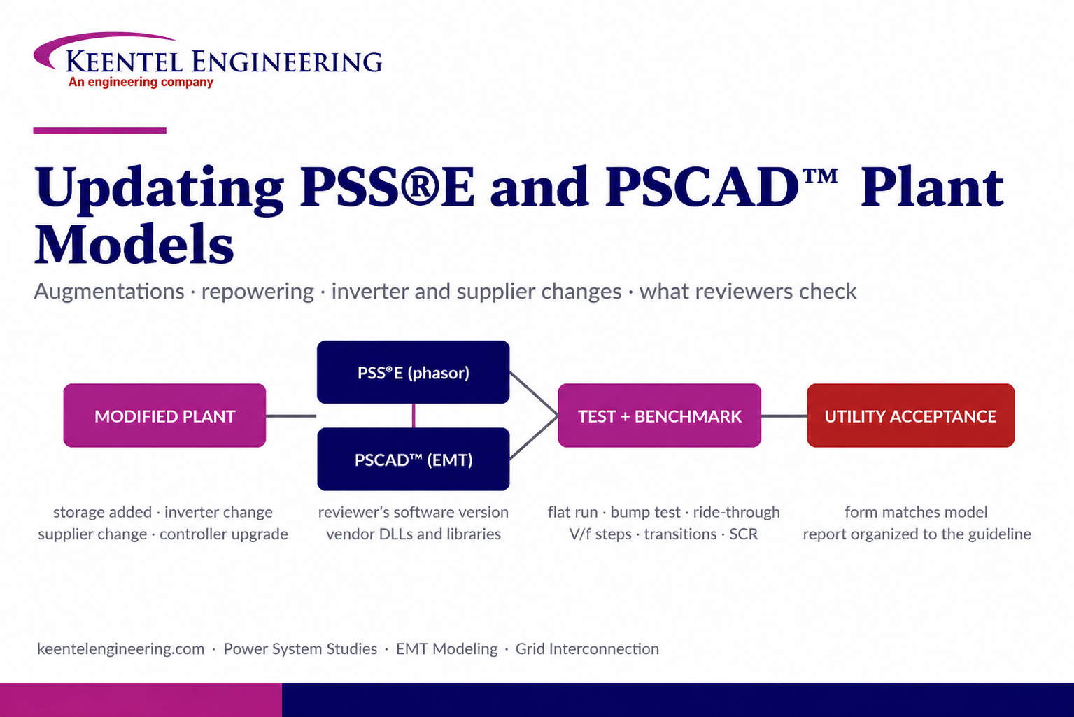
By SANDIP R PATEL
•
September 22, 2026
Learn how PSS®E and PSCAD™ model updates support plant augmentations, repowering, equipment changes, testing, benchmarking, and grid compliance.





