
A Coordinated Electric System Interconnection Review—the utility’s deep-dive on technical and cost impacts of your project.
Challenge: Frequent false tripping using conventional electromechanical relays
Solution: SEL-487E integration with multi-terminal differential protection and dynamic inrush restraint
Result: 90% reduction in false trips, saving over $250,000 in downtime
ERCOT enforces all of the above through simulation, which means your model is your compliance case. The bar is now high:
- Whole-facility scope. The model must represent everything the IT load, the UPS and power conversion, the cooling plant, the protection and control systems in formats compatible with ERCOT's study platforms (PSS/E, PSCAD, TSAT).
- Real control loops, not approximations. Generic textbook representations are unacceptable. The model must capture the actual inner control behavior of your power electronics.
- Hardware-validated converter models. For electronic loads, the PSCAD model must be benchmarked against actual hardware testing including voltage ride-through and subsynchronous response. A model assembled from standard PSCAD library blocks fails by definition, because a generic block has never been tested against your vendor's hardware. The good news: validation is a hardware-type test, so results for a given converter product are reusable across every facility that uses it.
- Format migration. Facilities that previously submitted the older composite load model (CMLD) format must transition to EPRI's PERC1 format.
- Three checkpoints. Models are reviewed before the stability study begins (no model, no study), before each quarterly stability assessment, and for electronic loads one final time before energization, when you must submit as-built models with a documented comparison against the previously studied data and a sworn attestation that the model matches actual field settings. ERCOT's review takes 10 business days, extendable by 20 put it on your critical path.
- A living obligation. Change your technology, controls, or relay settings in a way that affects ride-through including converting a crypto mining site to an AI data center — and you've triggered a new interconnection study, even if your megawatts don't change.
| Parameter | Detail |
|---|---|
| System | 230 kV / 138 kV transmission corridors, wind and wet-snow icing exposure |
| Data basis | 15 years of minute-resolution forced-outage records + regional weather observations |
| Core methods | Event grouping, MVA performance curves, time-to-95%-restore, area outage rate curves, fragility modeling, rerun-history benefits, exceedance and log-domain risk metrics |
| Headline result | ≈85% of maximum resilience benefit at 60% of original capital; worst-event restoration window cut from 11 days to 5 in rerun-history terms |
| Decision supported | Capital portfolio selection; resilience plan filing; post-investment verification framework |
| System / Topic | Governing Standard(s) | What It Controls |
|---|---|---|
| Overall plant electrical distribution | IEEE 141 (Red Book); IEEE 666 | Distribution architecture, voltage selection, design of generating station auxiliary service systems |
| Power system studies | IEEE 399 (Brown Book); IEEE 551 | Load flow, symmetrical/asymmetrical short circuit, motor starting methodologies down to the lowest LV panelboard |
| Protection & coordination | IEEE 242 (Buff Book); IEEE 3004.5; IEEE C37 series | Generator relaying (21, 59N, 87G), time-current coordination, selective clearing between LV and MV tiers |
| GSU / UAT / SST transformers | IEEE C57.12.00 and C57 family | Transformer ratings, impedance, testing, loading |
| HV switchyard breakers | IEEE C37.06 | AC high-voltage circuit breaker preferred ratings |
| MV switchgear (13.8 kV) | IEEE C37.20.2; IEEE C37.20.7 | Metal-clad construction, compartmentalization, vacuum breakers; arc-resistant design with plenum venting |
| MV cable | UL 1072; ICEA S-93-639 (NEMA WC 74) | Type MV-105 shielded cable, 133% insulation level for HRG systems |
| LV switchgear (480 V) | IEEE C37.13; UL 1558 | Metal-enclosed LV power circuit breaker switchgear to 635 V, draw-out ACBs with electronic trip units |
| Motor control centers | UL 845; NEMA ICS 18 | LV-MCC construction, MCCB/MCP protection for motors under ~200 HP |
| Motors | NEMA MG-1 | Motor performance, starting characteristics, service factors |
| DC & battery systems | IEEE 485; IEEE 946 | Lead-acid battery sizing (125/250 VDC), DC auxiliary system design |
| Grounding | IEEE 80; IEEE 142 (Green Book) | Ground grid step/touch potential limits; system grounding including high-resistance grounding |
| Lightning protection | IEEE 998 | Direct-stroke shielding of switchyard and outdoor generator structures |
| Arc flash & electrical safety | IEEE 1584; NFPA 70E | Incident energy calculation; worker safety boundaries and PPE |
| Fire protection | NFPA 850 | Fire protection and risk management for combustion turbine generating plants |
| Installation code | NEC (NFPA 70); NESC | Wiring methods inside the plant fence; overhead/outdoor clearances at the switchyard |
| Interconnection & compliance | FERC LGIP; NERC MOD-025/026/027, PRC-019/024/029, FAC-008 | Interconnection process, model validation, protection/ride-through coordination, facility ratings |
| IFC / Construction Deliverable | Purpose |
|---|---|
| Stamped IFC packages | Legal basis for construction; P.E. responsible charge |
| Final relay settings & TCCs | Protection as-installed matches the coordination study |
| Calculation archive | Owner records; NERC audit evidence trail |
| Commissioning procedures | Safe, sequenced energization; MOD field testing |
| Construction support | RFIs, field changes, FAT/SAT witness |
| As-builts & model handoff | Operating baseline; future study currency |
| Metric | Outcome |
|---|---|
| Defects found pre-occupancy | Three topology defects and one settings-mismatch family corrected before load migration; the shared-switchboard defect alone would have invalidated the concurrently-maintainable claim on day one |
| IST findings | Fourteen additional discrepancies surfaced under scenario testing (control logic, alarm mapping, one generator sequencing fault) — all closed before handover instead of during operations |
| Black-building test | Passed on second execution; the first attempt exposed the generator sequencing fault under true block load, exactly the failure the compressed plan would never have found |
| Handover quality | Operations team certified on the actual failure scenarios; corrected EOPs and settings documentation delivered as controlled documents |
| Business outcome | Occupancy proceeded three weeks behind the original date — against an independent estimate that the uncorrected sequencing fault carried a high probability of a full facility outage within the first year |
Part 2 — Frequently Asked Questions: Large Load Interconnection
An electric grid must remain in continuous balance — generation onto the grid must equal consumption from it at every instant. PJM achieves this balance, and prices it, through a layered market architecture. Each layer operates on a different time horizon, and each one touches project economics differently.
| Domain | Key Standards / Codes | What They Govern |
|---|---|---|
| Fire safety | NFPA 855; UL 9540 / UL 9540A | Installation requirements, separation, gas management; system safety listing and thermal-runaway fire testing |
| Grid interconnection | IEEE 1547 (distribution); IEEE 2800 (transmission IBRs) | Ride-through, reactive capability, power quality, and performance at the point of interconnection |
| Power quality | IEEE 519 | Harmonic distortion limits at the PCC |
| Protection & grounding | IEEE 80 / 81 / 142; C37 series | Grounding system design and testing; protective relaying |
| Reliability compliance | NERC standards (incl. PRC ride-through requirements) | Registered-entity obligations for grid-connected storage |
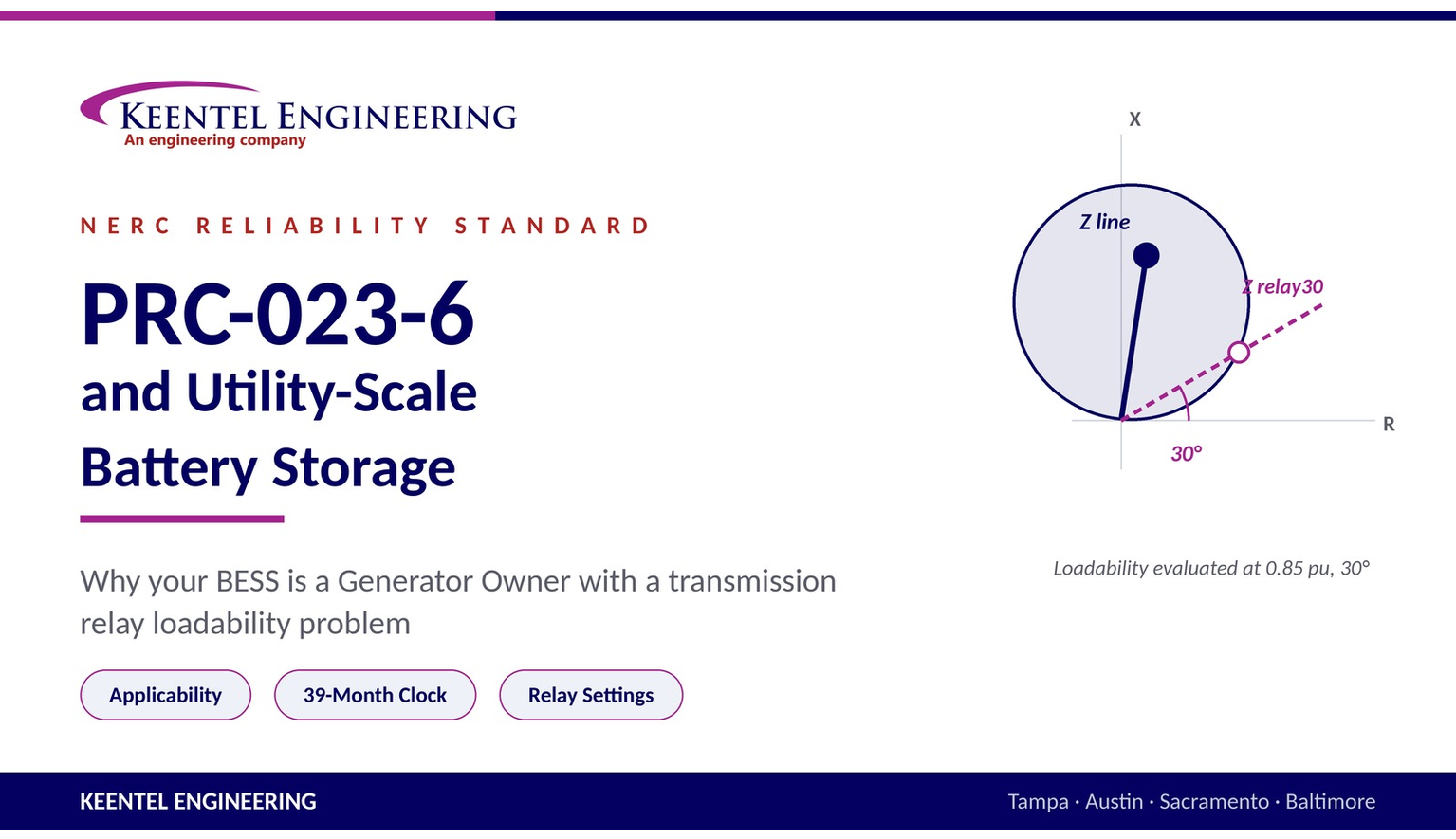
PRC-023-6 and Utility-Scale Battery Storage
Aug 19, 2026 | Blog
Why Your BESS Is a Generator Owner With a Transmission Relay Loadability Problem
An in-depth applicability, implementation-timing and relay-setting guide for battery energy storage Generator Owners.
Introduction
Most battery energy storage system (BESS) developers and owners build their NERC compliance program around the standards everyone talks about: PRC-024, PRC-028, PRC-029, PRC-030, MOD-026, MOD-032, FAC-008. Transmission relay loadability rarely makes the list. The assumption is understandable — PRC-023 has "Transmission" in its title, and a battery plant is a generator.
That assumption is wrong often enough to be expensive.
PRC-023-6 — Transmission Relay Loadability names the Generator Owner as an applicable functional entity in Section 4.1.2, in the same sentence and on the same terms as the Transmission Owner. It does not care whether the machine behind your relay is a steam turbine, a wind farm, or a 400 MWh lithium-iron-phosphate installation. It cares about one thing: whether you have applied load-responsive phase protection systems at the terminals of a circuit that falls within Section 4.2.1. If you have, you own Requirements R1 through R5, with a High Violation Risk Factor on R1 and a Violation Severity Level table that offers only one outcome — Severe.
Battery storage makes this harder than conventional generation for a reason that sits right in the text of the standard. The exemption that most generators rely on covers Elements "used exclusively to export energy directly from a BES generating unit or generating plant." A battery plant does not exclusively export. It imports at full nameplate, on a daily cycle, by design. Whether that single word survives contact with a bi-directional asset is the most consequential applicability question a storage Generator Owner will face, and it is not answered anywhere in the standard, the Technical Rationale, the Implementation Plan or the Implementation Guidance.
This article works through the whole problem: why a battery plant is a Generator Owner, exactly which parts of the standard reach it, how the effective dates and the 39-month implementation clock actually run, the relay-setting mathematics with fully worked 138 kV examples, the inverter-based-resource complications that make loadability and dependability collide, and what a defensible compliance program looks like in practice.
Part 1 — Regulatory Background: What PRC-023 Is Actually For
PRC-023 exists because of August 14, 2003.
During the Northeast blackout, distance relays — particularly overreaching Zone 3 elements — could not distinguish heavy load from a fault. Depressed voltage and high current during the cascade produced an apparent impedance that fell inside relay tripping characteristics, and lines that were thermally fine tripped anyway. Each trip shifted load onto the remaining circuits, which pushed their apparent impedance further into their own characteristics. The protection system stopped protecting the grid and started dismantling it.
The standard's Purpose statement carries both halves of the resulting lesson:
"Protective relay settings shall not limit transmission loadability; not interfere with system operators' ability to take remedial action to protect system reliability and; be set to reliably detect all fault conditions and protect the electrical network from these faults."
That is a security requirement (do not trip when you should not) with an explicit dependability boundary (but still clear every fault). PRC-023 is fundamentally about buying the system operator time. As NERC's Statement of Purpose in the Implementation Guidance puts it, relays should "not interfere with the system operators' ability to consciously take remedial action to protect system reliability," allowing "short-term overloads with sufficient margin to allow for inaccuracies in the relays and instrument transformers."
What changed in Version 6
PRC-023-6 came out of NERC Project 2021-05, Modifications to PRC-023. There are two substantive changes.
Requirement R2 was retired and is now marked "Reserved."
The old R2 required entities to set out-of-step (power swing) blocking elements to allow tripping of phase protective relays for faults occurring during the R1 loading conditions. The Standard Drafting Team's Technical Rationale makes an unusually candid case for retirement:
- R2's fault condition was a subset of R1's "all fault conditions," so any R2 violation was automatically an R1 violation. Retirement created no reliability gap.
- R2 traced back to an error in Appendix C of the 2006/2007 reference document Determination and Application of Practical Relaying Loadability Ratings, which discussed only electromechanical power-swing-blocking schemes and concluded a timer should force a trip — which the current SDT correctly notes "is not appropriate because tripping should not occur during the identified heavy load conditions unless a fault actually occurs."
- The original Attachment A language ("shall be evaluated to ensure that they do not block trip") was inverted when FERC's Order 733 ¶244 directive was implemented as a requirement ("shall set its out-of-step blocking elements to allow tripping"). That inversion shifted engineering attention from evaluating the scheme to constraining the blinder settings, and in at least one documented case an entity simply disabled two power-swing-blocking schemes rather than fight the requirement.
- Ten years of evidence supported retirement: only two R2 violations ever, both found in paperwork rather than operations and both assessed as minimal risk; roughly 40,000 operations across five years of MIDAS data yielding 11 candidate events and a single relay-related one; and 18 major NERC event-analysis reports plus the February 2008 FRCC disturbance showing no case of a fault going uncleared because of power swing blocking.
- Fleet modernization closed the gap independently. One entity went from 161 of 471 (34%) affected line terminals on electromechanical relays in 2011 to 19 of 699 (2.7%) by 2022.
Attachment A, Item 2.3 was retired.
The exclusion for "protection systems intended for protection during stable power swings" referenced schemes designed to separate portions of the system during stable swings — an application the SDT concluded no longer exists in North America, with PRC-026 covering the space adequately. Items 2.3 and 2.4 now both read "Reserved."
What this means for a BESS owner:
you no longer have a standalone power-swing-blocking requirement to satisfy, but the obligation did not vanish — it was absorbed into R1's "while maintaining reliable protection of the BES for all fault conditions." If you apply PSB or out-of-step logic at your point of interconnection, you still have to demonstrate that a fault occurring during PSB assertion will be detected and cleared. You simply document it under R1 now.
Part 2 — Why a Battery Storage Plant Is a Generator Owner
The registration chain
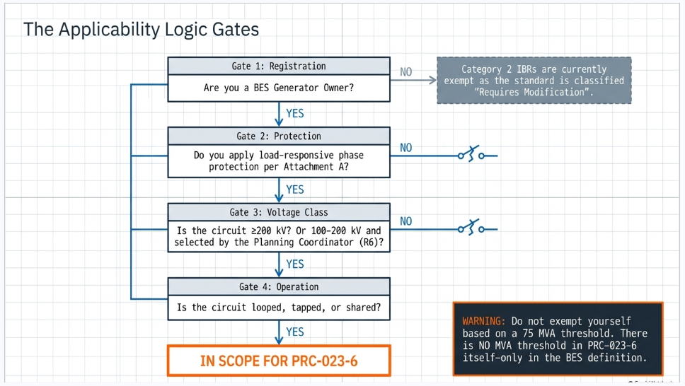
A utility-scale BESS becomes subject to PRC-023-6 through a chain of four links, and the standard only reaches you if all four hold.
- Your facility is part of the Bulk Electric System. Under the NERC BES definition, generating resources connected at 100 kV or above qualify through Inclusion I2 where individual units exceed 20 MVA gross nameplate or the plant aggregate exceeds 75 MVA, and through Inclusion I4 for dispersed power producing resources aggregating more than 75 MVA delivered through a system designed primarily for that purpose at 100 kV or above. Nearly every utility-scale battery plant — 100 MW and up, interconnected at 115 kV, 138 kV, 230 kV or 345 kV — clears these comfortably.
- You register as a Generator Owner. BES generating facilities register as GO/GOP. A battery plant discharging to the grid is a generating resource; it registers exactly as a solar or wind plant does.
- You apply load-responsive phase protection. Section 4.1.2 conditions Generator Owner applicability on having "load-responsive phase protection systems as described in PRC-023-6 - Attachment A, applied at the terminals of the circuits defined in 4.2.1."
- The circuit is in scope under Section 4.2.1. This is where most of the analysis lives, and where the storage-specific difficulty appears.
An important and widely misunderstood point about thresholds
There is a persistent piece of misinformation circulating in AI-generated and secondhand compliance content claiming that PRC-023-6 applies when a plant exceeds "75 MVA at a single point of interconnection" or contains "individual units greater than 20 MVA."
PRC-023-6 contains no MVA threshold anywhere — not in the Applicability section, not in the Requirements, not in either Attachment.
Those numbers come from the BES definition and drive whether you register at all. Once registered, PRC-023-6 applicability is determined entirely by (a) the presence of load-responsive phase protection per Attachment A and (b) the voltage class and Planning Coordinator designation of the circuit. Confusing the two leads directly to two failure modes: exempting yourself on a threshold that does not exist in the standard, or performing loadability studies on circuits that were never in scope.
The Category 2 IBR wrinkle — a genuine and current exemption
FERC Order 901 drove NERC's registration of previously unregistered inverter-based resources. Category 2 IBRs — non-BES inverter-based resources at or above 20 MVA aggregate nameplate connected at 60 kV or above — became registrable with a compliance date of May 15, 2026.
Newly registered Category 2 GO/GOPs do not inherit the full standards portfolio at once. NERC published a phased list of standards with Category 2 compliance dates: BAL-001-TRE, IRO-010-5, MOD-026-2, MOD-032-2, PRC-012-2, PRC-017-1, PRC-028-1, PRC-029-1, PRC-030-1, TOP-003-6.1, VAR-001-5 and VAR-002-4.1.
PRC-023 is not on that list. NERC classified it as
"Requires Modification" — meaning the standard would need revision before it could be applied to Category 2 IBRs, and no Category 2 compliance date has been established.
| Comparison Criteria | BES Generator Owner (traditional registration) | Category 2 IBR Generator Owner |
|---|---|---|
| Facility status | BES | Non-BES |
| Typical BESS profile | ≥100 kV interconnection, >75 MVA aggregate | 20–75 MVA aggregate, 60–100 kV connection |
| PRC-023-6 applicable today? | Yes, if Section 4.2.1 circuit criteria are met | No — classified "Requires Modification"; no compliance date set |
| Watch item | Planning Coordinator R6 circuit list | Future NERC standards development on PRC-023 for IBRs |
If your battery plant is a BES facility with a traditional GO registration — which describes the overwhelming majority of
utility-scale storage in ERCOT, CAISO, MISO, PJM and SPP — PRC-023-6 is live for you today, and the Category 2 phase-in provides no shelter.
Part 3 — The Applicability Analysis: Does PRC-023-6 Actually Reach Your Interconnection?
The circuits in scope
Section 4.2.1 defines six circuit categories subject to R1–R5:
| § | Circuit | Export exception present? |
|---|---|---|
| 4.2.1.1 | Transmission lines operated at 200 kV and above | Yes |
| 4.2.1.2 | Transmission lines operated at 100 kV to 200 kV, selected by the Planning Coordinator per R6 | Not directly (arrives via 4.2.2.1) |
| 4.2.1.3 | Transmission lines operated below 100 kV that are part of the BES, PC-selected per R6 | Not directly (arrives via 4.2.2.2) |
| 4.2.1.4 | Transformers with low voltage terminals connected at 200 kV and above | No |
| 4.2.1.5 | Transformers with low voltage terminals connected at 100 kV to 200 kV, PC-selected per R6 | No |
| 4.2.1.6 | Transformers with low voltage terminals connected below 100 kV that are part of the BES, PC-selected per R6 | No |
Two observations matter enormously for storage, and generic compliance summaries consistently miss both.
First, the transformer categories almost never capture a BESS GSU. Sections 4.2.1.4 through 4.2.1.6 are written in terms of the transformer's low-voltage terminal. A typical battery GSU steps 34.5 kV to 138 kV or 230 kV — its low side is 34.5 kV, so 4.2.1.4 (low side ≥200 kV) and 4.2.1.5 (low side 100–200 kV) cannot reach it. Those categories are aimed at transmission autotransformers, not generator step-up units. Only 4.2.1.6 could theoretically apply, and only if the transformer is part of the BES and your Planning Coordinator affirmatively selects it under R6 — an uncommon but not impossible outcome.
Second, the export exception is written into 4.2.1.1 and into both R6 categories (4.2.2.1 and 4.2.2.2), but not into the transformer categories. That asymmetry is deliberate, and it means the exemption analysis has to be performed per-Element against the specific subsection your circuit falls under — not as a blanket plant-level conclusion.
The exception, and why battery storage strains it
Section 4.2.1.1 excludes:
"Elements that connect the GSU transformer(s) to the Transmission system that are used exclusively to export energy directly from a BES generating unit or generating plant. Elements may also supply generating plant loads."
For a solar plant or a gas turbine this is straightforward: a radial gen-tie from the plant substation to the utility POI exports and does nothing else. It is out of scope, and PRC-025 picks up the loadability obligation instead.
For a battery plant, three separate problems appear.
Problem 1 — "exclusively to export"
A BESS gen-tie carries power in both directions as a matter of normal operation, often at full nameplate, frequently for more hours per year than it exports. Read strictly, an Element that imports several hundred megawatt-hours daily is not "used exclusively to export energy." Read purposively, the exception exists to keep radial generator leads out of a transmission standard, and a battery lead is still radial.
Neither reading is settled. The Technical Rationale for PRC-023-6 states plainly that "No changes are proposed to the Applicability of Reliability Standard PRC-023-6 from the prior version" — meaning the drafting team did not revisit this language when it revised the standard in 2021–2023, and the record contains no discussion of bi-directional resources at all. The language predates utility-scale storage as a mainstream asset class.
There is a meaningful textual signal in favor of treating bi-directionality as significant: Section 4.1.3 makes Distribution Providers applicable "provided those circuits have bi-directional flow capabilities." The drafters knew how to make bi-directional flow an applicability trigger — and they used it elsewhere in the same section.
Problem 2 — shared and hybrid configurations
The exception speaks of energy exported "directly from a BES generating unit or generating plant" — singular. Where a battery plant shares a gen-tie, a collector substation or a GSU with a co-located solar or wind facility owned by a different legal entity, or where two independently registered plants aggregate onto one lead, the "single plant, radial export" characterization becomes difficult to sustain. Hybrid and co-located configurations are now the norm rather than the exception in storage development, and they are the single most common route by which a storage owner ends up in scope.
Problem 3 — loop and three-terminal taps
Many BESS projects interconnect by looping an existing transmission line in and out of the plant substation, or by tapping it as a third terminal, because that is cheaper and faster than building a dedicated radial lead to a distant substation. The moment grid power can flow through your substation between two utility buses, the circuit is a network transmission element. It is not a generator lead under any reading, the export exception is unavailable, and if the line is 200 kV or above it is captured directly by 4.2.1.1 with no Planning Coordinator designation required at all.
The decision path
- Are you a BES Generator Owner, or a Category 2 IBR? Category 2 only → PRC-023-6 is not applicable today; monitor NERC standards development. BES GO → continue.
- Do you apply load-responsive phase protection per Attachment A at the terminals of any interconnection circuit? (Phase distance, phase overcurrent, out-of-step tripping, switch-onto-fault, communication-aided schemes, and phase fault detectors on current-based comm-assisted schemes that can trip on loss of communications.) No → not applicable. Yes → continue.
- What is the circuit's voltage class? ≥200 kV → captured by 4.2.1.1 unless the export exception holds. 100–200 kV or sub-100 kV BES → captured only if your Planning Coordinator selects it under R6 using Attachment B.
- Is the circuit radial, shared, or looped/tapped? Looped or tapped → in scope. Shared with another plant or another owner → the exception is very hard to sustain. Dedicated radial → the bi-directionality question is live and must be documented.
- Have you received an R6 circuit list from your Planning Coordinator? If your circuit is named on it, the analysis is over — you are in, and your 39-month clock has started.
The disciplined answer for a genuinely radial, standalone BESS gen-tie at 200 kV or above: you probably qualify for the export exception, but you should not treat that as self-evident. Write the position down, cite the Element-level analysis, state your reading of "exclusively to export," get your Planning Coordinator and Transmission Operator to acknowledge it in writing, and retain it. An undocumented exemption is indistinguishable from an oversight
when an auditor opens the file three years later.
Part 4 — Effective Dates and the Implementation Plan
This is where storage owners get caught, because the standard has two independent clocks, and the one that matters most to a new BESS is not the standard's effective date.
Clock 1 — The standard's own effective date
PRC-023-6 was developed under Project 2021-05; the Technical Rationale and Implementation Plan are dated January 2023. FERC approved PRC-023-6 by delegated letter order on January 24, 2024, in Docket No. RD23-5-000.
The Implementation Plan sets the effective date as the later of (i) the first day of the first calendar quarter after the effective date of the approving order, or (ii) the effective date of PRC-023-5. Applying that to a January 24, 2024 order places the U.S. effective date at April 1, 2024, with PRC-023-5 retired immediately prior.
Two documentation cautions worth knowing. The Version History table published inside the standard contains an apparent date typo in the Board-adoption row, and the 2024 RSAW's "Regulatory Language" section cites the March 4, 2022 order in Docket RD22-2-000 — which approved PRC-023-5, not -6. Verify enforcement dates against NERC's One-Stop-Shop rather than against the RSAW narrative.
PRC-023-6 has been enforceable for more than two years. There is no grandfathering for storage projects that reached commercial operation after that date.
Clock 2 — The 39-month rule, and why it governs new BESS projects
Section 5 of the standard and the Implementation Plan establish a separate compliance timeline for circuits that become applicable through the Planning Coordinator's R6 assessment:
Each Generator Owner, Transmission Owner, and Distribution Provider that owns circuits that become applicable to this standard pursuant to Requirement R6 shall become compliant with R1 through R5 on the later of the first day of the first calendar quarter 39 months following notification by the Planning Coordinator of a circuit's inclusion on a list of circuits per application of Attachment B, or the first day of the first calendar year in which any criterion in Attachment B applies, unless the Planning Coordinator removes the circuit from the list before the applicable effective date.
Worked timeline
Your Planning Coordinator's annual assessment identifies your 138 kV BESS interconnection under Attachment B criterion B4 and notifies you on March 12, 2027. Thirty-nine months later is June 12, 2030; the first day of the first calendar quarter following that point is July 1, 2030. If the PC's studies indicate the Attachment B criterion first applies in calendar year 2031, the later of the two dates governs and your compliance date becomes January 1, 2031.
Three things follow, and they are the practical heart of this article:
- The clock starts at notification, not at commercial operation. A BESS that energizes in 2027 can be notified in 2029 and be compliant by 2032 — but only if it is watching for the notice.
- The notice can arrive at any time. R6 Part 6.2 requires the PC to distribute the list within 30 calendar days of establishing it and within 30 calendar days of any change to it. Changes are driven by the PC's power flow work, not by your project schedule.
- The Planning Coordinator can also remove your circuit before the effective date, which is a real and legitimate outcome to pursue where the underlying study assumptions have changed.
The other dates you need on a compliance calendar
| Obligation | Frequency | Deadline | Who |
|---|---|---|---|
| R6 — PC Attachment B assessment | Annual | At least once per calendar year, no more than 15 months between assessments | Planning Coordinator |
| R6 Part 6.2 — distribute circuit list | Event-driven | Within 30 calendar days of establishing the list and of any change to it | Planning Coordinator |
| R4 — circuit list where criterion 2 (15-minute rating) is used | Annual | Once per calendar year, no more than 15 months between reports, to PC, TOP and RC | GO / TO / DP |
| R5 — circuit list where criterion 12 is used | Annual | Once per calendar year, no more than 15 months between reports, to the Regional Entity | GO / TO / DP |
| R3 — Facility Rating agreement for criteria 7, 8, 9, 12, 13 | Event-driven | Before relying on the calculated capability; requires PC, TOP and RC agreement | GO / TO / DP |
| Evidence retention, R1–R5 | Ongoing | Three calendar years | GO / TO / DP |
| PC first assessment under -6 | One-time | Next calendar year after the effective date, or within 15 months of its last PRC-023-4/-5 assessment, whichever is first | Planning Coordinator |
The trap in R4 and R5: they are annual reporting obligations triggered by a
setting choice. If your protection engineer selects criterion 2 or criterion 12 for a terminal and no one tells the compliance team, you acquire a recurring 15-month obligation that nobody is tracking. Both carry Lower Violation Risk Factors — but both have binary-Severe Violation Severity Levels. You either sent the report inside 15 months, or you did not.
Part 5 — How Attachment B Puts Your Circuit on the List
If your interconnection is between 100 kV and 200 kV — which covers a very large share of utility-scale storage — you are in scope only through your Planning Coordinator's Attachment B assessment. Understanding that screen tells you how to anticipate the notice.
Any one of six criteria puts a circuit on the list:
- B1 — The circuit is a monitored Facility of a permanent flowgate in the Eastern Interconnection, a major transfer path in the Western Interconnection as defined by the Regional Entity, or a comparable monitored Facility in the Québec Interconnection.
- B2 — The circuit is selected based on Planning Assessments of the Near-Term Transmission Planning Horizon that identify instability, Cascading or uncontrolled separation adversely affecting BES reliability for planning events.
- B3 — The circuit forms an agreed path supplying off-site power to a nuclear plant under NUC-001 Nuclear Plant Interface Requirements.
- B4 — The circuit is identified through a defined power flow screening sequence (detailed below).
- B5 — The circuit is selected by the PC based on other technical studies or assessments, in consultation with the Facility owner.
- B6 — The circuit is mutually agreed upon for inclusion by the Planning Coordinator and the Facility owner.
B4 is the one that catches storage. The sequence:
- Simulate double contingency combinations selected by engineering judgment, with no manual system adjustments between the two contingencies — modeling a System Operator who has no time to react.
- For 100–200 kV circuits, evaluate post-contingency loading, in consultation with the Facility owner, against a threshold based on the Facility Rating used in the PC's power flow case.
- Where multiple Facility Ratings exist, use the rating for the loading duration nearest four hours.
- Apply the duration-dependent threshold below.
- Radially operated circuits serving only load are excluded.
| Facility Rating loading duration | Circuit is in scope if post-contingency loading exceeds | On a 1,000 A / 239 MVA 138 kV circuit |
|---|---|---|
| Up to and including 4 hours | 115% of the Facility Rating | 1,150 A / 275 MVA |
| Greater than 4 and up to 8 hours | 120% of the Facility Rating | 1,200 A / 287 MVA |
| Greater than 8 hours | 130% of the Facility Rating | 1,300 A / 311 MVA |
Two takeaways for a storage owner.
First, B4 explicitly requires consultation with the Facility owner. You have a seat at the table, and the assumed Facility Rating used in the PC's case is worth verifying, because an understated rating in the power flow model can pull your circuit onto the list unnecessarily.
Second, a large BESS materially changes post-contingency flows on the surrounding 138 kV network in both directions. Charging at full nameplate during an off-peak double contingency is a legitimate stress case, and it is exactly the kind of scenario that pushes a neighbouring circuit past 115%. Your project can put
someone else's circuit on the list — a fact worth raising early in interconnection studies rather than discovering in a PC notification letter.
Part 6 — The Technical Core: Requirement R1 and the Setting Mathematics
The universal evaluation condition
Every R1 criterion is evaluated at the same operating point:
0.85 per unit voltage and a power factor angle of 30 degrees.
This is an assumed stressed-system condition for evaluating loadability — not a ride-through voltage, not a fault condition, and not a measured value. It represents a depressed-voltage, poor-power-factor state where apparent impedance is at its most threatening to a distance characteristic. Confusing it with PRC-024/PRC-029 ride-through voltage-time curves is one of the more common conceptual errors in this space, and it produces studies that answer the wrong question.
Failure to evaluate at 0.85 pu and 30° is, by itself, an independent path to a Severe VSL under R1 — the VSL table lists it as a standalone "OR" condition alongside failing to use one of the criteria.
The thirteen criteria — and the one that isn't there
R1 offers criteria numbered 1 through 13, but criterion 6 is Reserved. There are twelve usable options, and you need to satisfy only one per circuit terminal. Different terminals on the same circuit may use different criteria.
| # | Criterion | Threshold |
|---|---|---|
| 1 | Highest seasonal Facility Rating, duration nearest 4 hours | 150% |
| 2 | Highest seasonal 15-minute Facility Rating | 115% (triggers R4 annual reporting) |
| 3 | Maximum theoretical power transfer capability (90° across the line) | 115% |
| 4 | Series-compensated lines | Greater of 115% of the highest series capacitor emergency rating, or 115% of criterion 3 using full line inductive reactance |
| 5 | Weak source systems | 170% of maximum end-of-line three-phase fault magnitude |
| 6 | Reserved | — |
| 7 | Load centre terminal remote from generation | 115% of maximum current flow load→generation, any configuration (triggers R3) |
| 8 | Bulk-system end of lines serving remote load | 115% of maximum current system→load (triggers R3) |
| 9 | Load end of lines serving remote load | 115% of maximum current load→system (triggers R3) |
| 10 | Transformer fault protection; lines terminated only with a transformer | Greater of 150% of maximum nameplate (including all installed forced cooling) or 115% of the highest operator-established emergency rating; plus 10.1 mechanical withstand coordination |
| 11 | Transformer overload protection not meeting criterion 10 | Allow ≥150% nameplate or 115% emergency rating for ≥15 minutes, or supervise with top-oil ≥100 °C / winding hot spot ≥140 °C |
| 12 | Distance relays where protection genuinely limits capability | Max 125% of apparent impedance, MTA 90° or highest supported, evaluated at 0.85 pu / 30°, including an 87% setting component in the Facility Rating (triggers R3 and R5) |
| 13 | Other practical limitations | 115% of such limitations (triggers R3) |
For a battery plant interconnection, criteria 1, 2, 3, 5, 10 and 12 carry essentially all the weight. Criterion 5 deserves particular attention for storage sited at the end of long radial lines in weak parts of the network — a common siting pattern where land and interconnection queue position are cheapest.
The governing equations
Every distance-relay evaluation reduces to the same relationship, from the NERC Implementation Guidance:
Z relay30 = ( 0.85 × V L-L ) ⁄ ( √3 × k × I rating )
where k is the criterion's margin factor — 1.5 for criterion 1, 1.15 for criteria 2, 3, 7, 8, 9 and 13, and 1.70 for criterion 5. The result is the maximum permissible relay reach at a 30° load angle. Your actual relay reach at 30° must be at or below it.
For a mho characteristic at any maximum torque angle applied to any line angle:
Z relay = ( 1.25 × Z line ) ⁄ cos( MTA − θ line ) Z relay30 = Z relay × cos( MTA − 30° )
And where the relay actually limits circuit capability, the current the circuit can carry with the 15% margin at 0.85 pu is:
I relay30 = ( 0.341 × V relay ⁄ Z line ) × [ cos( MTA − θ line ) ⁄ cos( MTA − 30° ) ]
For three-terminal lines and lines with radial taps, every one of these expressions is rewritten in terms of apparent impedance — the in-feed-adjusted impedance seen from that terminal for a fault at the most electrically distant terminal — and loadability must be evaluated per terminal, because in-feed makes each terminal see a different apparent impedance. Storage projects that tap an existing line create exactly this configuration.
A note on the guidance document
NERC's Determination of Practical Transmission Relaying Loadability Settings V1.1 (March 2024) is published as Proposed Implementation Guidance and is marked "Not ERO Enterprise Endorsed." The equations reflect accepted industry practice and the standard expressly permits other technically comparable methodologies — but the document is not a compliance safe harbour.
Part 7 — Worked Example: A 138 kV BESS Interconnection
Common assumptions. 138 kV nominal. Conductor impedance 0.12 + j0.78 Ω/mile (line angle 81.25°). Highest seasonal Facility Rating for the duration nearest four hours: 1,000 A (239 MVA). Zone 2 mho phase distance element set at 125% of line impedance.
Criterion 1 threshold, common to both cases:
Z relay30 (max) = ( 0.85 × 138,000 ) ⁄ ( √3 × 1.5 × 1,000 ) = 45.15 Ω
Equivalently, the relay must not operate at or below 1,500 A at 0.85 pu and 30°.
Case A — 18-mile shared gen-tie (BESS co-located with solar)
Z line = 2.16 + j14.04 Ω, |Z| = 14.21 Ω at 81.25°.
| MTA | Z relay | Z relay30 | Trip current at 0.85 pu / 30° | Result |
|---|---|---|---|---|
| 85° | 17.79 Ω | 10.21 Ω | 6,635 A | PASS — 4.42× margin |
| 90° | 17.97 Ω | 8.98 Ω | 7,539 A | PASS — 5.03× margin |
A short, shared gen-tie passes criterion 1 with enormous margin. The compliance work here is documentary, not corrective: because the tie is shared between two plants it does not qualify for the export exception, so the circuit is in scope — and you need a calculation summary on file proving what is obvious to the engineer but invisible to the auditor. This is the single most common storage scenario: in scope, compliant, and undocumented.
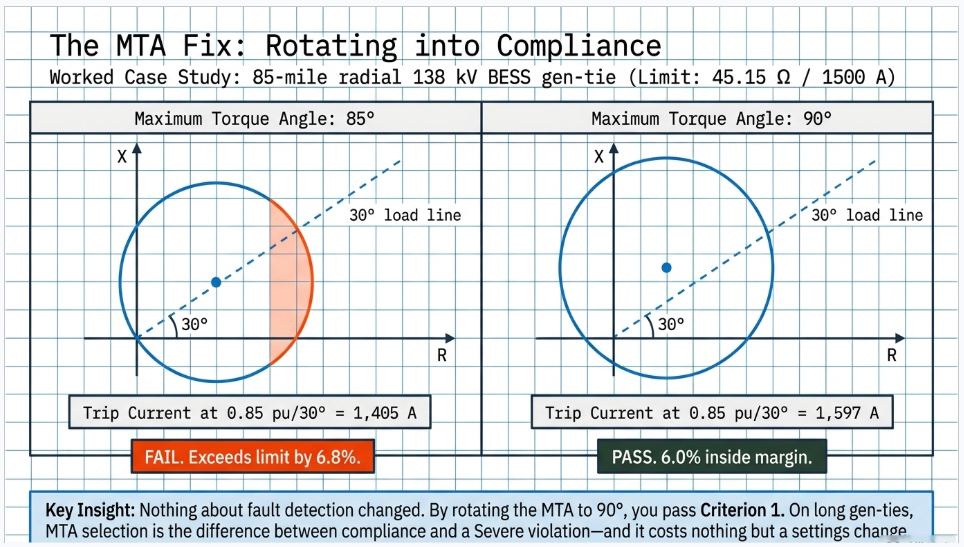
Case B — 85-mile radial gen-tie to a remote BESS
Z line = 10.20 + j66.30 Ω, |Z| = 67.08 Ω at 81.25°.
| MTA | Z relay | Z relay30 | Trip current at 0.85 pu / 30° | vs. 45.15 Ω limit | Result |
|---|---|---|---|---|---|
| 85° | 84.03 Ω | 48.20 Ω | 1,405 A | exceeds by 6.8% | FAIL |
| 90° | 84.84 Ω | 42.42 Ω | 1,597 A | 6.0% inside | PASS |
This is the most useful single result in the article. The identical relay, on the identical line, with the identical 125% reach, fails criterion 1 at an 85° maximum torque angle and passes it at 90°. Nothing about fault detection changed. The mho circle simply rotated, pulling its 30° chord away from the load region.
This is precisely why R1 criterion 12(a) instructs setting the MTA "to 90 degrees or the highest supported by the manufacturer," and why the Implementation Guidance states it is "prudent that the relays be adjusted to as close to the 90-degree MTA setting as the relay can be set to achieve the highest level of loadability without compromising the ability of the relay to reliably detect faults." On long gen-ties — a defining characteristic of remote storage siting — MTA selection is the difference between compliance and non-compliance, and it costs nothing but a settings change.
What if 90° still isn't enough?
Check the other criteria before assuming a problem. Criterion 3 for this line: X L = 66.30 Ω, so I total = 0.816 × 138,000 / 66.30 = 1,698 A, requiring the relay not to operate at or below 115% = 1,953 A — that is, Z relay30 ≤ 34.67 Ω. Criterion 3 is more restrictive here than criterion 1, which is a useful reminder that you should select the criterion that fits your circuit rather than defaulting to whichever one you used last time. You only need to satisfy one.
If no criterion can be met with an acceptable reach, criterion 12 is the designed exit — but it is an expensive one. It requires you to:
- limit the setting to 125% of apparent impedance with MTA at 90° or the highest supported;
- compute the circuit capability — here I relay30 = 1,387 A;
- include a relay setting component of 87% of that current in the Facility Rating determination — 1,206 A;
- under R3, adopt the calculated capability as the Facility Rating of the circuit and obtain the agreement of the Planning Coordinator, Transmission Operator and Reliability Coordinator;
- under R5, report the associated circuits to your Regional Entity annually, no more than 15 months apart, so the ERO can compile a list of every circuit in North America whose capability is limited by protection.
That last point is worth internalizing. Criterion 12 does not merely change a relay setting — it publicly derates your interconnection and puts your project on an ERO-wide list of protection-limited circuits. For a merchant storage asset whose revenue depends on the ability to move energy at scale, that is a commercial decision as much as an engineering one, and it belongs in front of the asset manager before the setting is issued.
The GSU transformer under criterion 10
For a 150 MVA top-rated BESS GSU on a 138 kV system, the maximum nameplate rating corresponds to 628 A on the HV side, so 150% = 941 A. If operations has established an emergency rating of 700 A, 115% of it is 805 A. Criterion 10 takes the greater — 941 A. And under criterion 10.1, any load-responsive transformer fault protection must be shown, via coordination curves, not to expose the transformer beyond the mechanical withstand capability illustrated by the "dotted line" in IEEE C57.109, Clause 4.4, Figure 4.
Criterion 11 provides the alternative for overload protection that cannot meet criterion 10: allow at least 150% of nameplate or 115% of the emergency rating for at least 15 minutes so an operator can act, or supervise tripping with a top-oil element set no lower than 100 °C or a simulated winding hot spot element no lower than 140 °C.
Part 8 — What Attachment A Actually Sweeps In at a Battery Plant
Attachment A is not a list of relays — it is a list of protective functions that could trip on load current, with or without time delay.
Included
Phase distance; out-of-step tripping; switch-onto-fault; overcurrent relays; communication-aided schemes including POTT, PUTT, DCB and DCUB; and — critically for modern storage — phase overcurrent supervisory elements (phase fault detectors) associated with current-based, communication-assisted schemes such as pilot wire, phase comparison and line current differential, where the scheme is capable of tripping for loss of communications.
That last inclusion catches a great many BESS interconnections. Line current differential is the default choice for a gen-tie, and engineers routinely assume a differential scheme is inherently load-immune. It is — until the loss-of-communications fallback logic arms a phase fault detector that is not. If your 87L scheme can trip on comms failure, the supervising phase element is in scope and must be evaluated.
Excluded
Elements enabled only when other relays or systems fail (loss-of-potential overcurrent; loss-of-communications elements except as noted above); ground fault protection; items 2.3 and 2.4 (Reserved); relay elements used only in Remedial Action Schemes approved under PRC-012 through PRC-017; protection designed only to respond in periods allowing 15 minutes or greater to respond to overload; thermal emulation relays used with dynamic Facility Ratings; and relay elements associated with dc lines and dc converter transformers.
Two exclusions are frequently over-claimed at storage sites. RAS-related elements are excluded only where the RAS is applied and approved under PRC-012 through PRC-017 — an informal owner-designed runback scheme does not qualify. And thermal emulation relays are excluded only where used in conjunction with dynamic Facility Ratings; a thermal element on a static rating is not exempt.
Switch-onto-fault deserves its own paragraph at a BESS
Appendix D of the Implementation Guidance is explicit: SOTF protection must not operate assuming the line terminals are closed at the outset and carrying up to 1.5 times the Facility Rating. For existing SOTF schemes, the protection must not operate when a breaker closes into an unfaulted line energized from the remote terminal at a voltage exceeding 85% of nominal at the local terminal; for schemes commissioned after formal adoption of the report, the threshold tightens to 75%. Battery plants cycle their POI breaker far more often than a conventional plant ever will, which makes SOTF logic both more valuable and more exposed.
Part 9 — The Inverter-Based Resource Complications
PRC-023-6 was written for a synchronous grid, and applying it at a battery plant surfaces genuine engineering tension that the standard does not address.
Fault current is limited, and that squeezes the setting window from both ends
A synchronous machine contributes 5–6 per unit into a close-in fault. A grid-following inverter contributes roughly 1.1–1.2 per unit, because current limiting is a firmware property, not an impedance. PRC-023 pushes the relay characteristic smaller to preserve loadability, while R1's own text demands "reliable protection of the BES for all fault conditions." At a BESS, the margin between "largest load current the relay must ride through" and "smallest fault current the relay must detect" can approach unity. The classic remedy — enlarge the characteristic — is precisely what PRC-023 prohibits.
Criterion 5 is often the right tool and is often overlooked
Where the maximum line-end three-phase fault current is small relative to the conductor's thermal capability — the textbook definition of a weak source, and an accurate description of many inverter-dominated pockets — criterion 5 permits setting against 170% of the maximum end-of-line three-phase fault magnitude rather than against a thermal rating. The 1.70 factor derives from 1.15 × √2 × 1.05: margin for device error, the √2 relationship at maximum power transfer, and a 1.05 pu bus voltage assumption.
Distance element behaviour degrades
Inverter controls do not produce the negative-sequence signature that conventional directional and phase-selection logic depends on, and IBR current angle is a control decision rather than a physical impedance response. Memory polarization, phase selection and directional integrity all deserve explicit scrutiny during the same study that establishes loadability — because a reach reduction taken for PRC-023 compliance can quietly compromise dependability for a resistive line-end fault.
Quadrilateral and load-encroachment characteristics are the practical answer
Appendix C of the Implementation Guidance notes that quadrilateral and other non-mho shapes allow smaller resistive reach settings for both protection and power swing blocking without encroaching on the loadability characteristic. On modern numerical relays this is usually a better answer than shrinking a mho circle until it no longer sees faults.
Power swing blocking still has to be evaluated, R2's retirement notwithstanding
Appendix C sets out the acceptable mitigation techniques: unblocking timers, adaptive timers based on measured swing rate, negative/zero-sequence reset, quadrilateral shapes, PSB characteristics with logic requiring the locus to be inside both the protection and PSB characteristics, and continuous monitoring of swing centre voltage. Under PRC-023-6 you document these under R1 rather than R2.
Where PRC-023-6 stops and the neighbouring standards start
| Standard | What it governs | Relationship to a BESS |
|---|---|---|
| PRC-023-6 | Loadability of phase protection on transmission circuits | Applies if your interconnection circuit is in Section 4.2.1 scope |
| PRC-025-2 | Loadability of load-responsive relays on generating units, GSU transformers, UATs, Elements connecting the GSU to the transmission system, and Elements aggregating dispersed power producing resources | Applies to the generator-side assets — including the very Elements PRC-023 excepts |
| PRC-024-4 / PRC-029-1 | Frequency and voltage protection settings and ride-through | Different physics, different curves — do not conflate with 0.85 pu / 30° |
| PRC-026-2 | Relay performance during stable power swings | Absorbed the space vacated by PRC-023 Attachment A item 2.3 |
| PRC-019 | Coordination of generating unit controls with protection and equipment capabilities | Where inverter current limits and protection settings must be reconciled |
| PRC-027-1 / PRC-001 | Protection system coordination | Overall coordination obligations |
| PRC-028-1 / PRC-030-1 | Disturbance monitoring and unexpected IBR event mitigation | Category 2 compliance dates of 4/1/2025 and 10/1/2026 |
| IEEE 2800-2022 | IBR interconnection technical requirements | Increasingly referenced in interconnection agreements; not a NERC standard |
The elegant point, and the one to take away
PRC-025-2 Section 4.2 expressly lists "Elements that connect the GSU transformer(s) to the Transmission system" as an applicable facility. These are the same Elements that PRC-023-6 Section 4.2.1.1 carves out. The two standards were deliberately drafted to hand the gen-tie back and forth so that no Element goes unaddressed.
Escaping PRC-023 through the export exception does not reduce your obligations — it relocates them to PRC-025-2 and its Attachment 1 setting tables. Any consultant who tells you a battery plant has "no relay loadability obligation" has answered only half the question.
Part 10 — What a Battery Storage Generator Owner Actually Needs to Do
A defensible program has ten components.
- Determine and document your registration track. BES Generator Owner or Category 2 IBR. The answer decides whether PRC-023-6 applies at all today. Write it down with the BES-definition analysis that supports it.
- Build an Element-level inventory of the interconnection. Every terminal from the collector bus outward: MV collector feeders, LV and HV sides of the GSU, the gen-tie, the POI breaker(s), any tapped or looped transmission. For each, record voltage class, ownership boundary, radial versus networked configuration, and which section of 4.2.1 it could fall under.
- Inventory protective functions against Attachment A, not against relay model numbers. Enumerate every function that can trip on load current — 21, 67, 50/51 phase, 68 out-of-step trip, SOTF, POTT/DCB/DCUB, and phase fault detectors supervising 87L schemes that can trip on loss of communications. Do this from settings files and logic diagrams, not from equipment lists.
- Take a written position on the export exception. For each Element, state whether 4.2.1.1's exception applies, and confront the bi-directional question directly rather than eliding it. Address shared, hybrid, looped and tapped configurations explicitly. Have your Planning Coordinator and Transmission Operator acknowledge the position in writing.
- Establish a Planning Coordinator interface. Confirm you are on the distribution list for the R6 circuit list. Ask when the annual assessment is performed. Participate in the Attachment B B4 consultation — the standard entitles you to it. Verify the Facility Rating your PC is using for your circuit in its power flow case, and check whether your charging profile is being modelled in the double-contingency screen at all.
- Perform the loadability study at 0.85 pu and 30° for every in-scope terminal. Select the criterion per terminal. Optimize the MTA toward 90° before concluding non-compliance. Evaluate three-terminal and tapped lines per terminal using apparent impedance. Check that any reach reduction preserves fault detection at the reduced fault-current levels an inverter-based plant actually produces.
- Escalate the criterion 12 decision to the business. If criterion 12 is the only viable path, the consequences — R3 tri-party Facility Rating agreement, an 87% relay component embedded in the rating, R5 annual reporting to the Regional Entity, and a public derate of the interconnection — belong in front of the asset owner before settings are issued.
- Build the evidence package to the RSAW's shape, in advance. The 2024 RSAW asks for a list of relays subject to R1 and spreadsheets or calculation summaries showing each relay is set to one of the criteria; for criterion 10, coordination curves demonstrating the transformer is not exposed beyond its withstand capability; for criteria 7/8/9/12/13, the Facility Rating record plus dated correspondence evidencing PC, TOP and RC agreement; and for R4/R5, dated correspondence proving transmittal inside 15 months. Auditors sample. Every relay in the sample must resolve to a criterion and a calculation.
- Put the recurring obligations on a compliance calendar with owners and 90-day reminders. R4 and R5 annual reports, three-year evidence retention, and a standing check for PC list updates. These are the requirements that fail quietly.
- Re-verify after every material change. New inverter blocks, a capacity expansion, a co-located resource added to your tie, a relay replacement, a re-rated conductor, a revised Facility Rating, a network reconfiguration that turns a radial lead into a loop — any of these can move an Element into scope or invalidate a prior calculation. The Implementation Guidance is explicit that criterion 3 results "should be reverified whenever major system changes are made."
Where BESS owners get this wrong
- Assuming "we're a generator, so PRC-023 doesn't apply." Section 4.1.2 names the Generator Owner directly.
- Relying on an MVA threshold that does not exist in the standard.
- Treating the export exception as plant-level rather than Element-level.
- Overlooking phase fault detectors in line current differential schemes.
- Missing the Planning Coordinator's R6 notification and losing months off a 39-month clock — or missing the compliance date entirely.
- Choosing criterion 2 or 12 without registering the annual R4/R5 reporting obligation it creates.
- Never optimizing the MTA, and concluding a long gen-tie cannot comply when a settings change would have resolved it.
- Confusing 0.85 pu / 30° with ride-through, and producing a study that answers a PRC-024 question.
- Documenting nothing, because the engineering answer was
obvious. An auditor cannot sample your intuition.
Part 11 — Why Work With Keentel Engineering
PRC-023-6 compliance for a battery storage plant sits at the intersection of three disciplines that rarely live in the same team: protection engineering (relay characteristics, apparent impedance, coordination with inverter fault-current limits), transmission planning (Attachment B power flow screening, Facility Ratings, Planning Coordinator negotiation), and NERC compliance (evidence construction, RSAW alignment, recurring reporting obligations).
A study that is technically correct but undocumented fails an audit. A tidy evidence binder built on the wrong applicability determination fails worse. Keentel Engineering brings all three to the same table.
Power System Studies
Short circuit and load flow modelling, relay loadability calculations at 0.85 pu and 30° across every R1 criterion, apparent-impedance analysis for three-terminal and tapped configurations, MTA optimization, and coordination checks that confirm a reach reduction taken for loadability has not compromised fault detection at inverter-limited current levels.
POI Interconnection Engineering Support
Applicability determinations at the Element level, Planning Coordinator and Transmission Operator engagement, Attachment B criterion B4 consultation support, and Facility Rating agreements under R3 with the PC, TOP and RC.
Substation Design and Transmission Line Design
Where the answer is a design change rather than a settings change — protection scheme selection, characteristic shape, instrument transformer ratios, gen-tie configuration — the same team that identifies the problem can engineer the fix.
Utility-Scale Renewable Energy and Owner's Engineer Services
Deep familiarity with how storage and hybrid projects are actually built, contracted and commissioned, so compliance obligations are identified during design rather than discovered during an audit.
NERC O&P 693 Compliance Services
Audit-ready evidence packages structured to the RSAW, compliance calendars for the R4/R5 annual reporting obligations, three-year evidence retention programs, and support through Regional Entity engagement.
Category 2 IBR registration and the broader IBR standards portfolio
PRC-023 does not arrive alone. Keentel supports PRC-024-4 and PRC-029-1 ride-through, PRC-028-1 disturbance monitoring, PRC-030-1, PRC-025-2 generator relay loadability, MOD-026 and MOD-032 modelling, and Category 2 registration — so a single applicability review covers the whole portfolio instead of one standard at a time.
Get in touch
Phone: 813-389-7871 | Email: contact@keentelengineering.com
Offices: Tampa (HQ) · Austin · Sacramento · Baltimore | keentelengineering.com
If you own or are developing utility-scale storage and cannot answer, today, whether your interconnection Elements are in PRC-023-6 scope — or whether your Planning Coordinator has already put your circuit on a list — that is the conversation to have now, while the 39-month clock is still an asset rather than a liability.
Frequently Asked Questions
Does PRC-023-6 apply to a battery storage plant?
It can. PRC-023-6 Section 4.1.2 names the Generator Owner as an applicable functional entity where load-responsive phase protection systems described in Attachment A are applied at the terminals of circuits defined in Section 4.2.1. Whether your specific Elements fall inside 4.2.1 depends on voltage class, configuration, the export exception, and your Planning Coordinator's Requirement R6 assessment.
Our BESS gen-tie is radial and only serves our plant. Are we exempt?
Possibly, but not automatically. The Section 4.2.1.1 exception covers Elements "used exclusively to export energy directly from a BES generating unit or generating plant." A battery plant imports as a matter of normal operation, so "exclusively to export" is an open interpretive question that the standard, the Technical Rationale and the Implementation Plan do not resolve. Document your position and confirm it with your Planning Coordinator rather than assuming it.
We share a gen-tie with a co-located solar plant. Does that change anything?
Significantly. A shared tie or shared GSU serving two plants — particularly under different ownership — is difficult to characterize as exporting "directly from a BES generating unit or generating plant" in the singular. Shared and hybrid configurations are the most common route by which storage owners end up in scope.
Is there an MVA threshold for PRC-023-6 applicability?
No. The 20 MVA and 75 MVA figures that appear in secondhand summaries come from the BES definition and determine registration, not PRC-023-6 applicability. The standard itself contains no MVA test.
Our BESS is registering as a Category 2 IBR. Does PRC-023-6 apply?
Not currently. NERC's phased list of standards applicable to Category 2 IBRs does not include PRC-023, which is classified as "Requires Modification" with no Category 2 compliance date established. This exemption does not extend to BES Generator Owners under traditional registration.
When is PRC-023-6 effective?
FERC approved it by delegated letter order on January 24, 2024 in Docket No. RD23-5-000, placing the U.S. effective date at the first day of the following calendar quarter — April 1, 2024. Separately, entities whose circuits become applicable through the Planning Coordinator's R6 assessment have until the later of the first day of the first calendar quarter 39 months after notification, or the first day of the first calendar year in which an Attachment B criterion applies.
What is the 39-month rule?
It is the implementation window for newly designated circuits. The clock starts when your Planning Coordinator notifies you that your circuit is on the Attachment B list — not at commercial operation, and not at the standard's effective date. Missing the notification is the most common way to lose the benefit of the window.
How many R1 criteria are there really?
Thirteen are numbered, but criterion 6 is Reserved, leaving twelve usable options. You need to satisfy only one per circuit terminal, and different terminals may use different criteria.
Requirement R2 was retired. Do we still have to worry about power swing blocking?
Yes, but you document it differently. R2 was retired as redundant to R1's "all fault conditions" language, and Attachment A item 2.3 was retired alongside it. If you apply power swing blocking, you must still be able to show that a fault occurring during PSB assertion will be detected and cleared — now under R1.
If we are exempt from PRC-023-6, are we free of relay loadability obligations?
No. PRC-025-2 Section 4.2 expressly covers generating units, GSU transformers, unit auxiliary transformers, Elements that connect the GSU transformer(s) to the transmission system, and Elements aggregating dispersed power producing resources. The two standards were drafted to hand the gen-tie back and forth so no Element goes unaddressed.
What evidence will an auditor ask for?
Per the 2024 RSAW: a list of relays subject to R1; spreadsheets or calculation summaries showing each relay is set to one of the R1 criteria; coordination curves for criterion 10 transformer protection; Facility Rating records and dated PC/TOP/RC correspondence for criteria 7, 8, 9, 12 and 13; and dated correspondence evidencing R4 and R5 annual transmittals. Retention is three calendar years.
References
- NERC Reliability Standard PRC-023-6 — Transmission Relay Loadability (Requirements R1–R6, Attachments A and B, Violation Severity Levels, Version History).
- NERC, Technical Rationale for Reliability Standard PRC-023-6, Project 2021-05, January 2023.
- NERC, Implementation Plan, Project 2021-05 Modifications to PRC-023, Reliability Standard PRC-023-6, January 2023.
- NERC System Protection and Control Working Group, Determination of Practical Transmission Relaying Loadability Settings V1.1 — Implementation Guidance for PRC-023-6, March 2024 (Proposed Implementation Guidance — Not ERO Enterprise Endorsed).
- NERC, Reliability Standard Audit Worksheet, PRC-023-6, Version 1, March 27, 2024.
- NERC Reliability Standard PRC-025-2 — Generator Relay Loadability.
- NERC, ERO Enterprise CMEP Practice Guide: Application of the Registration Criteria for Category 2 Generator Owner and Generator Operator Inverter-Based Resources.
- NERC, Reliability Standards Compliance Dates for Generator Owners / Generator Operators (Category 2 IBRs).
- IEEE C57.109, IEEE Guide for Liquid-Immersed Transformers Through-Fault-Current Duration; IEEE C57.91; IEEE C37.113.
- FERC Order No. 733, Transmission Relay Loadability Reliability Standard; FERC delegated letter order, Docket No. RD23-5-000 (January 24, 2024).
This article is provided for general informational purposes and reflects the referenced NERC documents as of publication. It is not legal advice and does not constitute a compliance determination for any specific facility. Applicability of PRC-023-6 depends on facility-specific configuration, registration status and Planning Coordinator determinations. Registered entities should verify current standard versions and enforcement dates against NERC's One-Stop-Shop and consult their Regional Entity and Planning Coordinator.
© Keentel Engineering · Tampa · Austin · Sacramento · Baltimore

About the Author:
Sandip "Sonny" R. Patel, P.E.
IEEE Senior Member · Founder & CEO, Keentel Engineering
In 1995, Sonny Patel earned his Electrical Engineering degree from the University of Illinois. But degrees don't build legacies — action does.
For three decades, he has worked the power industry from every side of the table: 16 years as a utility engineer at Exelon/Commonwealth Edison; generation leadership across hydroelectric, industrial steam turbine, and a 9 GW renewable fleet; NERC Regional Entity Senior Compliance Engineer and Audit Team Lead, auditing some of the nation's largest utilities; and testing and commissioning lead on equipment up to 765 kV — the very top of the North American grid.Utility. Generator. Regulator. Consultant. Few engineers have seen all four seats. Fewer still have sat in them.
His experience spans nuclear, hydro, conventional generation, renewables, oil and gas, mining — and today's data centers, where he is authoring a three-book series on data center design. He is a Licensed Professional Engineer in six states and a Licensed Electrical Contractor in Florida (Unlimited EC) — he doesn't just design the work; he's qualified to stand behind its execution.Today, as Founder and CEO of Keentel Engineering, Sonny leads a nationwide team of engineers delivering substation design, power system studies, NERC compliance, and commissioning — done right, coast to coast.Three decades. Every side of the table. One standard: accountable engineering.
Services

Let's Discuss Your Project
Let's book a call to discuss your electrical engineering project that we can help you with.
About the Author:
Sandip "Sonny" R. Patel, P.E.
IEEE Senior Member · Founder & CEO, Keentel Engineering
In 1995, Sonny Patel earned his Electrical Engineering degree from the University of Illinois. But degrees don't build legacies — action does.
For three decades, he has worked the power industry from every side of the table: 16 years as a utility engineer at Exelon/Commonwealth Edison; generation leadership across hydroelectric, industrial steam turbine, and a 9 GW renewable fleet; NERC Regional Entity Senior Compliance Engineer and Audit Team Lead, auditing some of the nation's largest utilities; and testing and commissioning lead on equipment up to 765 kV — the very top of the North American grid.
Utility. Generator. Regulator. Consultant. Few engineers have seen all four seats. Fewer still have sat in them.
His experience spans nuclear, hydro, conventional generation, renewables, oil and gas, mining — and today's data centers, where he is authoring a three-book series on data center design. He is a Licensed Professional Engineer in six states and a Licensed Electrical Contractor in Florida (Unlimited EC) — he doesn't just design the work; he's qualified to stand behind its execution.
Today, as Founder and CEO of Keentel Engineering, Sonny leads a nationwide team of engineers delivering substation design, power system studies, NERC compliance, and commissioning — done right, coast to coast.Three decades. Every side of the table. One standard: accountable engineering.
Leave a Comment
Thank you for contacting us.
We will get back to you as soon as possible.
We will get back to you as soon as possible.
Oops, there was an error sending your message.
Please try again later.
Please try again later.
Related Posts

By SANDIP R PATEL
•
September 30, 2026
Learn NERC and ERCOT compliance requirements for natural gas power plants, including GO/GOP obligations, O&P standards, GADS reporting, and audits.

By SANDIP R PATEL
•
September 26, 2026
Learn how to prepare a MISO large-load interconnection package, including PSS®E models, BESS smoothing, harmonic data and transmission-owner requirements.

By SANDIP R PATEL
•
September 26, 2026
Learn where storage belongs in an 800 VDC AI data center, including capacitors, flywheels, BESS, fault current, protection, grounding, and EMT design.

By SANDIP R PATEL
•
September 26, 2026
Learn how SPP’s HILL and HILLGA framework works for large-load projects, including studies, BTM generation, modeling, EMT requirements, and firm service.

By SANDIP R PATEL
•
September 25, 2026
Learn how IBR time synchronization, IEEE 2800, IRIG-B verification, and PTP solutions help meet disturbance monitoring compliance requirements.

By SANDIP R PATEL
•
September 24, 2026
Learn why continuing technical training matters in power engineering, including standards, software skills, PDH requirements, and career growth.
By SANDIP R PATEL
•
September 22, 2026
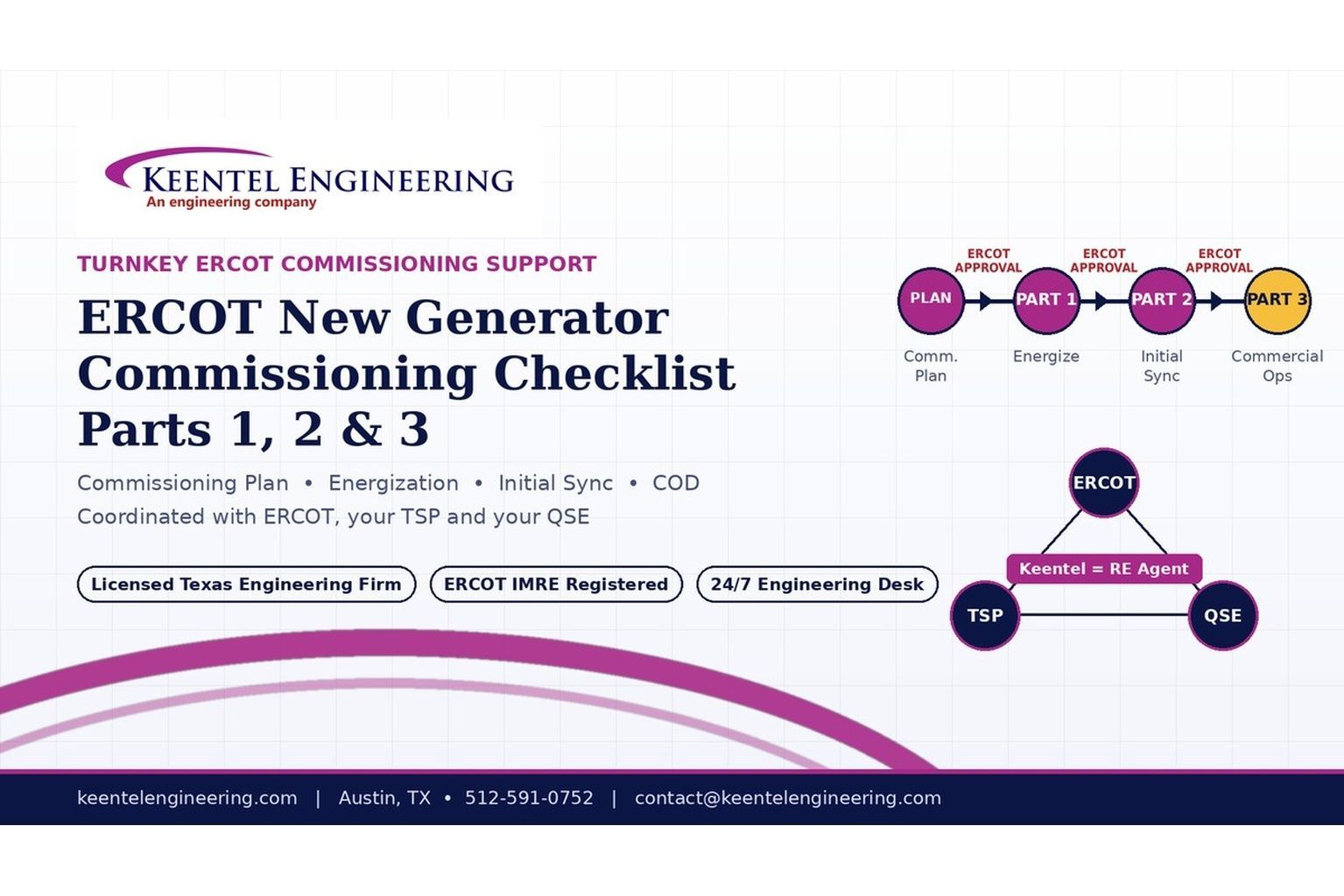
2026 ERCOT commissioning guide covering the Commissioning Plan, Checklist Parts 1–3, BESS requirements, TSP/QSE coordination, field testing and COD.

By SANDIP R PATEL
•
September 22, 2026
Learn PRC-030-1 R1 event detection requirements for inverter-based resources, SEL platforms, disturbance monitoring, and audit-ready compliance.
By SANDIP R PATEL
•
September 22, 2026
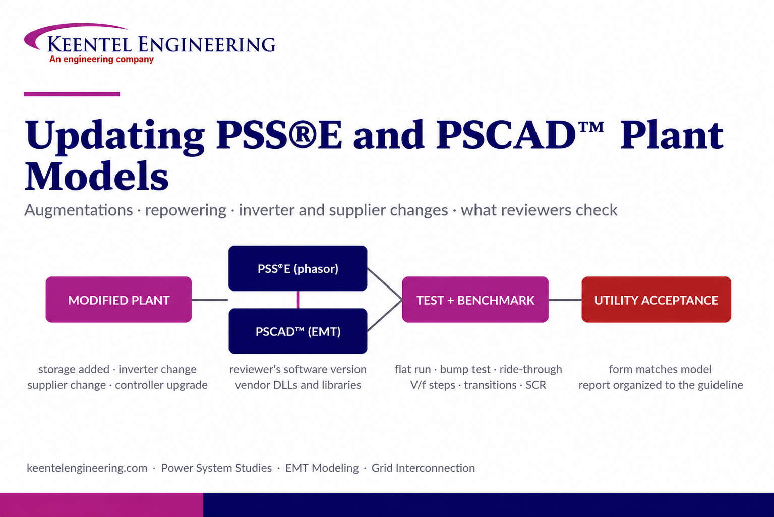
Learn how PSS®E and PSCAD™ model updates support plant augmentations, repowering, equipment changes, testing, benchmarking, and grid compliance.





