
A Coordinated Electric System Interconnection Review—the utility’s deep-dive on technical and cost impacts of your project.
Challenge: Frequent false tripping using conventional electromechanical relays
Solution: SEL-487E integration with multi-terminal differential protection and dynamic inrush restraint
Result: 90% reduction in false trips, saving over $250,000 in downtime
ERCOT enforces all of the above through simulation, which means your model is your compliance case. The bar is now high:
- Whole-facility scope. The model must represent everything the IT load, the UPS and power conversion, the cooling plant, the protection and control systems in formats compatible with ERCOT's study platforms (PSS/E, PSCAD, TSAT).
- Real control loops, not approximations. Generic textbook representations are unacceptable. The model must capture the actual inner control behavior of your power electronics.
- Hardware-validated converter models. For electronic loads, the PSCAD model must be benchmarked against actual hardware testing including voltage ride-through and subsynchronous response. A model assembled from standard PSCAD library blocks fails by definition, because a generic block has never been tested against your vendor's hardware. The good news: validation is a hardware-type test, so results for a given converter product are reusable across every facility that uses it.
- Format migration. Facilities that previously submitted the older composite load model (CMLD) format must transition to EPRI's PERC1 format.
- Three checkpoints. Models are reviewed before the stability study begins (no model, no study), before each quarterly stability assessment, and for electronic loads one final time before energization, when you must submit as-built models with a documented comparison against the previously studied data and a sworn attestation that the model matches actual field settings. ERCOT's review takes 10 business days, extendable by 20 put it on your critical path.
- A living obligation. Change your technology, controls, or relay settings in a way that affects ride-through including converting a crypto mining site to an AI data center — and you've triggered a new interconnection study, even if your megawatts don't change.
| Parameter | Detail |
|---|---|
| System | 230 kV / 138 kV transmission corridors, wind and wet-snow icing exposure |
| Data basis | 15 years of minute-resolution forced-outage records + regional weather observations |
| Core methods | Event grouping, MVA performance curves, time-to-95%-restore, area outage rate curves, fragility modeling, rerun-history benefits, exceedance and log-domain risk metrics |
| Headline result | ≈85% of maximum resilience benefit at 60% of original capital; worst-event restoration window cut from 11 days to 5 in rerun-history terms |
| Decision supported | Capital portfolio selection; resilience plan filing; post-investment verification framework |
| System / Topic | Governing Standard(s) | What It Controls |
|---|---|---|
| Overall plant electrical distribution | IEEE 141 (Red Book); IEEE 666 | Distribution architecture, voltage selection, design of generating station auxiliary service systems |
| Power system studies | IEEE 399 (Brown Book); IEEE 551 | Load flow, symmetrical/asymmetrical short circuit, motor starting methodologies down to the lowest LV panelboard |
| Protection & coordination | IEEE 242 (Buff Book); IEEE 3004.5; IEEE C37 series | Generator relaying (21, 59N, 87G), time-current coordination, selective clearing between LV and MV tiers |
| GSU / UAT / SST transformers | IEEE C57.12.00 and C57 family | Transformer ratings, impedance, testing, loading |
| HV switchyard breakers | IEEE C37.06 | AC high-voltage circuit breaker preferred ratings |
| MV switchgear (13.8 kV) | IEEE C37.20.2; IEEE C37.20.7 | Metal-clad construction, compartmentalization, vacuum breakers; arc-resistant design with plenum venting |
| MV cable | UL 1072; ICEA S-93-639 (NEMA WC 74) | Type MV-105 shielded cable, 133% insulation level for HRG systems |
| LV switchgear (480 V) | IEEE C37.13; UL 1558 | Metal-enclosed LV power circuit breaker switchgear to 635 V, draw-out ACBs with electronic trip units |
| Motor control centers | UL 845; NEMA ICS 18 | LV-MCC construction, MCCB/MCP protection for motors under ~200 HP |
| Motors | NEMA MG-1 | Motor performance, starting characteristics, service factors |
| DC & battery systems | IEEE 485; IEEE 946 | Lead-acid battery sizing (125/250 VDC), DC auxiliary system design |
| Grounding | IEEE 80; IEEE 142 (Green Book) | Ground grid step/touch potential limits; system grounding including high-resistance grounding |
| Lightning protection | IEEE 998 | Direct-stroke shielding of switchyard and outdoor generator structures |
| Arc flash & electrical safety | IEEE 1584; NFPA 70E | Incident energy calculation; worker safety boundaries and PPE |
| Fire protection | NFPA 850 | Fire protection and risk management for combustion turbine generating plants |
| Installation code | NEC (NFPA 70); NESC | Wiring methods inside the plant fence; overhead/outdoor clearances at the switchyard |
| Interconnection & compliance | FERC LGIP; NERC MOD-025/026/027, PRC-019/024/029, FAC-008 | Interconnection process, model validation, protection/ride-through coordination, facility ratings |
| IFC / Construction Deliverable | Purpose |
|---|---|
| Stamped IFC packages | Legal basis for construction; P.E. responsible charge |
| Final relay settings & TCCs | Protection as-installed matches the coordination study |
| Calculation archive | Owner records; NERC audit evidence trail |
| Commissioning procedures | Safe, sequenced energization; MOD field testing |
| Construction support | RFIs, field changes, FAT/SAT witness |
| As-builts & model handoff | Operating baseline; future study currency |
| Metric | Outcome |
|---|---|
| Defects found pre-occupancy | Three topology defects and one settings-mismatch family corrected before load migration; the shared-switchboard defect alone would have invalidated the concurrently-maintainable claim on day one |
| IST findings | Fourteen additional discrepancies surfaced under scenario testing (control logic, alarm mapping, one generator sequencing fault) — all closed before handover instead of during operations |
| Black-building test | Passed on second execution; the first attempt exposed the generator sequencing fault under true block load, exactly the failure the compressed plan would never have found |
| Handover quality | Operations team certified on the actual failure scenarios; corrected EOPs and settings documentation delivered as controlled documents |
| Business outcome | Occupancy proceeded three weeks behind the original date — against an independent estimate that the uncorrected sequencing fault carried a high probability of a full facility outage within the first year |
Part 2 — Frequently Asked Questions: Large Load Interconnection
An electric grid must remain in continuous balance — generation onto the grid must equal consumption from it at every instant. PJM achieves this balance, and prices it, through a layered market architecture. Each layer operates on a different time horizon, and each one touches project economics differently.
| Domain | Key Standards / Codes | What They Govern |
|---|---|---|
| Fire safety | NFPA 855; UL 9540 / UL 9540A | Installation requirements, separation, gas management; system safety listing and thermal-runaway fire testing |
| Grid interconnection | IEEE 1547 (distribution); IEEE 2800 (transmission IBRs) | Ride-through, reactive capability, power quality, and performance at the point of interconnection |
| Power quality | IEEE 519 | Harmonic distortion limits at the PCC |
| Protection & grounding | IEEE 80 / 81 / 142; C37 series | Grounding system design and testing; protective relaying |
| Reliability compliance | NERC standards (incl. PRC ride-through requirements) | Registered-entity obligations for grid-connected storage |
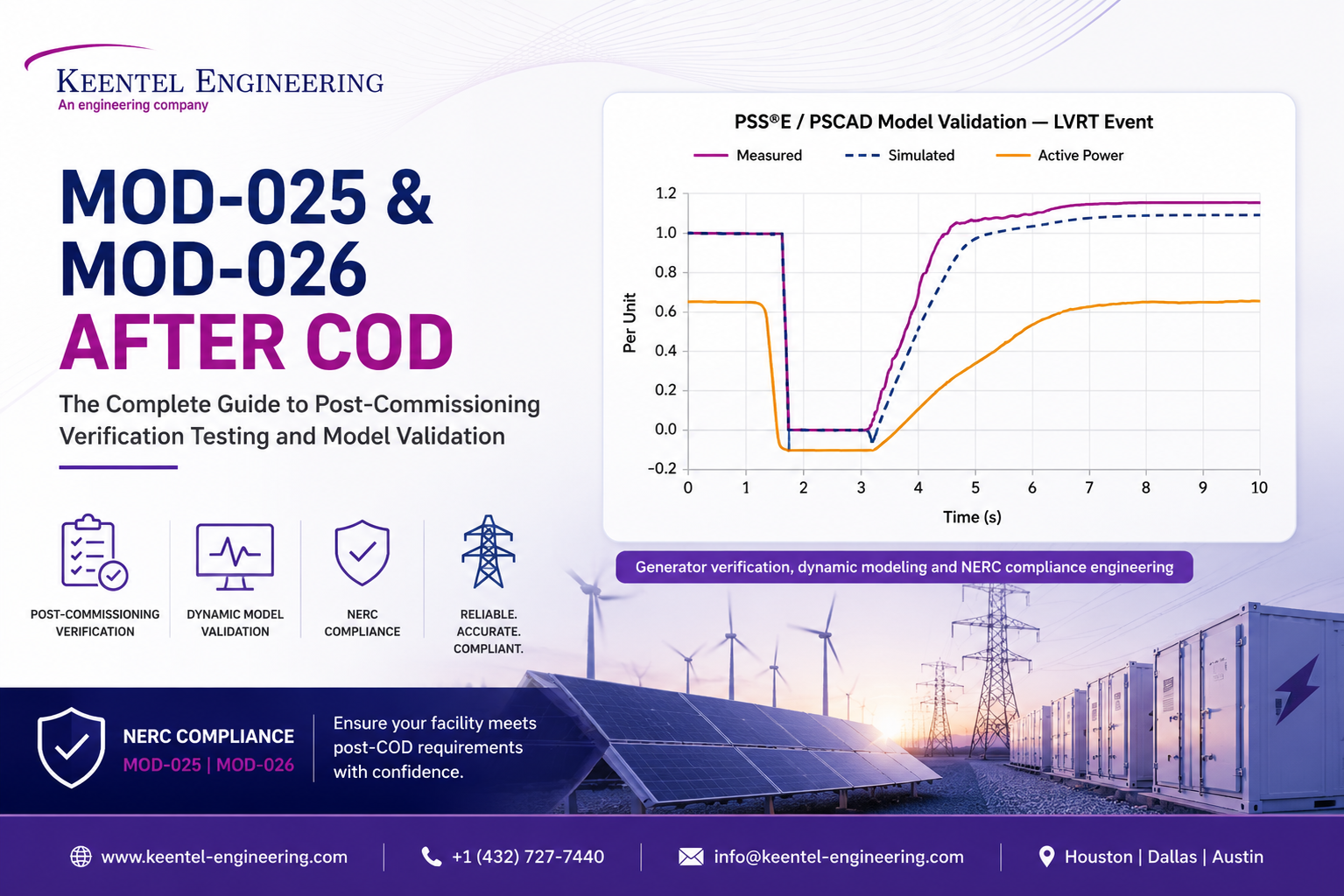
MOD-025 and MOD-026 After COD: The Complete Guide to Post-Commissioning Verification Testing and Model Validation
Aug 15, 2026 | Blog
Keentel Engineering | Generator verification, dynamic modeling and NERC compliance engineering
The 12 months after COD are the ones that catch people out
A generating facility spends years in the interconnection queue. Studies are run, models are submitted, equipment is procured, the plant is built, and one day it produces its first megawatt-hour. Commercial operation date. The project team celebrates and moves on to the next asset.
And then, quietly, two compliance clocks start running.
The first is MOD-025 — verification of the facility's real and reactive power capability, due within twelve months of the commercial operation date. The second is MOD-026 — verification and validation of the dynamic models the facility relies on, due within roughly a year of commissioning for a new resource. Neither of these is satisfied by the interconnection study package. Neither is satisfied by the OEM's generic model. Both require the registered entity to demonstrate, with evidence, that the as-built, as-commissioned, as-operating facility behaves the way the grid planner's models say it does.
This is where a surprising number of otherwise well-run projects get into trouble. The interconnection model was a design-stage artifact. The plant that actually got built has different firmware, different plant controller settings, different protection thresholds, and often a different reactive capability than the one that was studied. Post-COD verification is the process of closing that gap — and documenting that you closed it.
This guide walks through what MOD-025 and MOD-026 actually require after COD, how the testing works on site and off site, what "model verification" and "model validation" really mean in PSS®E and PSCAD, the findings that come up again and again, and how to build an evidence package that survives an audit.
Part 1 — What MOD-025 actually requires
The short version
MOD-025-2, Verification and Data Reporting of Generator Real and Reactive Power Capability and Synchronous Condenser Reactive Power Capability, asks a deceptively simple question: can your plant actually produce the real and reactive power that the planning models and registration data say it can?
The Generator Owner must verify both, document the verification on a standardized form, and submit it to the Transmission Owner, Transmission Planner and Planning Coordinator.
Who it applies to
The standard applies to Generator Owners with:
- individual generating units greater than 20 MVA, or
- generating plants with an aggregate nameplate rating greater than 75 MVA,
that are directly connected to the Bulk Electric System. Transmission Owners carry a parallel obligation for synchronous condensers greater than 20 MVA.
For a utility-scale solar or storage facility, the aggregate threshold is the one that matters. Practically every utility-scale inverter-based resource in North America is in scope.
The requirements
- R1 — Real Power. Verify the real power capability of the generating units in accordance with Attachment 1, and submit the completed Attachment 2 form within 90 calendar days of the date the test data was recorded or the historical data was selected.
- R2 — Reactive Power. Verify reactive power capability, over-excited and under-excited, on the same basis and with the same 90-day submittal clock.
- R3 — Transmission Owners carry the equivalent obligation for synchronous condensers.
The periodicity and the post-COD trigger
Three timing rules govern MOD-025:
- New facilities: within 12 calendar months of the commercial operation date. This is the post-COD trigger and it is the one most frequently missed.
- Recurring: at least once every five years, with no more than 66 calendar months between verifications.
- On change: within 12 months of discovery of a capability change exceeding ten percent that persists for more than six months.
That third trigger deserves attention at storage and hybrid facilities, where augmentation, cell replacement, inverter firmware changes and repowering can move capability materially.
The 90-day trap
Entities often plan carefully around the 12-month COD deadline and then lose the submittal. The 90-day clock runs from the data recording or selection date, not from the deadline. A test run in month three of the compliance year must be submitted by month six — waiting until month eleven is a violation even though the annual deadline has not passed.
Attachments 1 and 2
Attachment 1 contains the substance: the periodicity schedule, the verification specifications, the data recording requirements, and the specification for the one-line diagram that must accompany the submittal. It tells you what has to be measured, where, and to what standard.
Attachment 2 is the reporting form — the one-line diagram, the data table organized by measurement point, the verification data summary, and the ambient conditions at the time of verification.
The point of measurement is a recurring source of confusion. Capability is not simply the sum of inverter nameplate ratings. It is what the facility can deliver at the agreed measurement point, after collector system losses, transformer losses, auxiliary and station service load, and any reactive limits imposed by the plant controller. Getting the measurement point and the correction methodology right is most of the engineering.
What is different about an inverter-based resource
MOD-025 was written in a world of synchronous machines, and the language still reflects that. Applying it to a solar plant or a battery introduces practical problems that have nothing to do with the standard's text:
- Real power capability depends on resource availability. A solar plant cannot demonstrate full real power output at 4 p.m. in December. Verification must be scheduled against irradiance, or qualifying historical operating data must be screened out of the historian.
- Curtailment interferes. ERCOT curtailment, congestion, or a basepoint below capability can invalidate a test window.
- Reactive capability is voltage-dependent and control-mode-dependent. The reactive capability an IBR can actually deliver at the point of measurement varies with POI voltage, inverter AC voltage, active power output, and whether the plant controller is in voltage, power factor or reactive power control mode.
- Reactive capability is often limited by settings, not hardware. This is the single most common MOD-025 finding at IBR plants — the equipment can do more than the plant controller is configured to allow.
- Storage adds a second quadrant. A BESS must be considered charging as well as discharging, and reactive capability may differ between the two.
None of this changes the requirement. It changes the planning that has to go into it.
Part 2 What MOD-026 actually requires
Verification versus validation
MOD-026 is the standard that trips people up, largely because two similar words mean two very different things.
Model verification asks: does the model represent the equipment that is actually installed? It is a documentation and parameter exercise. You compare the model's configurable, site-specific parameters against the as-commissioned inverter settings, plant controller configuration, protection thresholds, transformer data and firmware versions, and you demonstrate traceability from the field to the model.
Model validation asks: does the model reproduce what the plant actually did? It is a simulation exercise. You take a real event — a staged test or a recorded system disturbance — replay it against the model, and compare simulated response to measured response.
MOD-026 requires both. Passing one does not satisfy the other. A model can be perfectly parameterized and still fail to reproduce a recorded fault response; a model can happen to match one event and still contain parameters that bear no relationship to the installed equipment.
Applicability under MOD-026-2
The revised standard developed under Project 2020-06 substantially broadens the resource types in scope:

| Resource type | Threshold |
|---|---|
| Synchronous generators (ERCOT) | > 50 MVA individual, or > 75 MVA aggregate |
| Synchronous generators (Eastern / Québec) | > 100 MVA (Eastern), per region |
| Dynamic reactive resources — synchronous condensers, FACTS | > 20 MVA |
| HVDC — line-commutated and voltage-source converters | Per applicability table |
| Inverter-based resources — BES and non-BES aggregates | ≥ 20 MVA at ≥ 60 kV |
| Units identified by the Transmission Planner | Where simulated response does not match measured behavior |
That last row matters. A Transmission Planner who observes a mismatch between your plant's recorded behavior and its modeled behavior can require verification on technical justification alone, outside the normal periodicity.
Version check. MOD-026-1 has been the enforceable version for years, and MOD-026-2 was developed and balloted under Project 2020-06 with a phased implementation. Before you build a compliance plan around specific dates, confirm the enforceable version, the approved implementation plan, and the phase applicable to your facility with your Regional Entity and Planning Coordinator. The engineering below applies either way; the deadlines do not.
The requirements, in plain language
- R1 — the Transmission Planner and Planning Coordinator jointly define the rules. Model specifications consistent with MOD-032, acceptance criteria, submittal process, and — critically for inverter-based resources — EMT model requirements and formats. You cannot scope a MOD-026 submittal without first obtaining your TP/PC's R1 criteria. They differ between regions, and ERCOT's are specific.
- R2 — submit a verified positive-sequence dynamic model. The obligation is to demonstrate that configurable, site-specific parameters represent the parameters of the in-service equipment, with supporting documentation of model structure and parameter accuracy.
- R3 — submit a verified EMT model for inverter-based resources, FACTS, HVDC and synchronous condensers. This includes large-signal disturbance test comparisons, verification of site-specific parameters, representation of enabled protections and limiting functions, and validation against recorded active and reactive power events.
- R4 — change management. When hardware, software or control settings change in a way that alters dynamic response, submit an updated model or a verification plan within the timeframes in Attachment 2 — up to 180 days after return to service.
- R5 — the Transmission Planner reviews within 120 calendar days and either accepts or denies with explanation.
- R6 — you have 120 calendar days to respond to a denial or a model review request with updated models, a verification plan, or additional justification.
Periodicity
| Condition | Timeline |
|---|---|
| Newly commissioned facility | 365 days after commissioning |
| Recurring verification | 10-year anniversary of the most recent transmittal |
| Equipment, firmware or control change | 180 days after return to service |
| Response to a plan-to-verify submittal | 365 days after the plan is submitted |
| Transmission Planner review | 120 days from receipt |
| Response to denial or review request | 120 days |
Acceptable validation methods
Model validation must be based on one of two sources:
- Staged tests — factory type tests, hardware-in-the-loop assessments, or manufacturer tests, and
- Measured system disturbances — the facility's recorded response to actual transmission system events.
For volt/var and reactive validation, the selected event must involve a genuine dynamic reactive excursion; a slow, quiescent voltage drift proves nothing. For active power and frequency validation, the event must meet the applicable perceived frequency deviation threshold — 0.10 Hz in ERCOT and the Western Interconnection, 0.05 Hz in the Eastern Interconnection, and 0.15 Hz in Québec.
Where qualifying results cannot be obtained, the standard requires that the reason be documented. "We could not find an event" is an acceptable position only if you can show you looked, that your monitoring was capable of capturing one, and that you have said so in writing.
What Attachment 1, Table 1.2 asks of an inverter-based resource
For IBRs, FACTS and HVDC, the model content requirements group into four areas:
- Facility identification — manufacturer, model numbers, and software/firmware versions actually in service.
- Volt/VAR control models — inverter electronic controls, the plant controller, and any supplemental reactive resources such as STATCOMs, capacitor banks or reactors.
- Frequency and active power control models — active power controls, ramp rates, and frequency response, with model validation.
- Protective and limiting functions — enabled limiters (power, current, ramp rate) and protections (voltage, frequency) that directly trip or block units or the facility.
Item 4 is where model quality most often falls down, and it is the item with the most direct reliability consequence.
Part 3 Post-COD testing: on site and off site
What can be done remotely, and what cannot
A well-run post-COD verification program divides cleanly into work that must happen at the plant and work that is better done off site.
Requires site presence or site coordination:
- Staged reactive capability testing that sweeps the plant across its operating envelope
- Verification of instrumentation, CT/PT circuits and metering accuracy at the point of measurement
- Confirmation of time synchronization at the device level — GPS, IRIG-B, PTP or NTP distribution
- Retrieval of settings files and event records from devices without remote access
- Witnessing of inverter or plant controller functional behavior where remote visibility is limited
Better done off site:
- Test plan development and TSP/ISO coordination
- Screening of historian and disturbance records for qualifying events
- Parameter comparison between field settings and model files
- All PSS®E and PSCAD simulation work
- Model tuning, validation plotting, and quantitative comparison
- Report preparation, Attachment 2 completion, and evidence assembly
The practical model that works for most owners is remote engineering support during a site-executed test, with an option to attend on site for the first campaign, for a complex hybrid facility, or where the O&M provider has not run this type of test before. Keentel Engineering supports both — on-site witnessing and fully off-site engineering — and most programs end up as a blend.
Planning a MOD-025 verification at an IBR plant
A workable sequence:
- Confirm the point of measurement and the correction methodology before anything else. Every number in the submittal depends on it.
- Decide test versus historical data. If the historian holds qualifying operating points — full real power at a representative ambient, plus over- and under-excited reactive excursions — historical data avoids a staged test entirely. This is often the fastest and cheapest route, and it is fully compliant.
- Coordinate with ERCOT and the TSP. Reactive testing moves POI voltage. It requires notice, a voltage schedule accommodation, and sometimes an outage coordination entry.
- Set the data acquisition up properly. Real power, reactive power, voltage and current at the measurement point, plant controller mode and setpoints, individual inverter status, ambient temperature and irradiance, all time-synchronized, at a resolution and duration that satisfies Attachment 1.
- Run the test against the plant's actual limits. The objective is to find the boundary, not to confirm a number someone typed into the RARF three years ago.
- Reconcile with registration data. If verified capability differs from the RARF, the RARF gets updated. Silent divergence is a finding waiting to happen.
- Complete Attachment 2 and submit inside 90 days.
Planning a MOD-026 validation campaign
MOD-026 validation is less about scheduling a test and more about being able to capture an event when one occurs. That means:
- Disturbance monitoring that records voltage, current, active power, reactive power and frequency at adequate resolution
- Records long enough to capture pre-event, event and recovery
- Plant controller and inverter-level data, not just substation relay data
- Time synchronization good enough to align substation records with inverter records
- A retention policy that keeps the records long enough to be useful
Facilities that have this in place can usually satisfy MOD-026 validation from recorded disturbances without a staged test. Facilities that do not are forced into staged testing, OEM type-test records, or a documented explanation of why validation data could not be obtained — and that last option invites scrutiny.
This is also the point where MOD-026 and PRC-028 overlap in a useful way. The disturbance monitoring capability that PRC-028 requires is precisely the capability that makes MOD-026 validation straightforward. Owners who treat them as one program rather than two save real money.
Part 4 PSS®E modeling: what verification really involves
A positive-sequence model verification is not "we sent the OEM's .dyr file." A defensible verification covers:
Structure and configuration
- Correct model modules selected for the inverter, electrical controls and plant controller
- Correct interconnection of those modules
- Plant equivalent impedance, collector system representation and transformer data consistent with the as-built facility
- Consistency with the MOD-032 data submitted to the Planning Coordinator
Parameter traceability
- Every configurable, site-specific parameter mapped to a field source — an inverter settings file, a plant controller configuration export, a relay setting, a nameplate
- Reactive control mode, droop, deadband, time constants and limits matching the commissioned plant controller
- Active power controls, ramp rates and frequency droop matching the commissioned configuration
- Voltage and frequency trip parameters matching the protection actually in service
Behavior
- Clean initialization and a flat run with no drift
- Numerically stable response across the study cases
- Sensible response to voltage steps, faults and frequency events
- No premature blocking or tripping in a region where the resource is required to ride through
That last point is the bridge between MOD-026 and PRC-024 / PRC-029. A model whose trip parameters do not match the field is not just a modeling problem — it can be masking a ride-through non-conformance, or manufacturing a phantom one that causes the Planning Coordinator to derate your plant in studies.
The findings that come up over and over
- Plant controller reactive limits in the model that do not match the commissioned configuration
- Voltage and frequency trip settings modeled from a design specification rather than the relay settings actually loaded
- Momentary cessation represented in the model but disabled in firmware — or the reverse
- Firmware version in service newer than the version the model package was issued for
- Frequency droop and deadband defaults never updated to the ERCOT-required values
- Ramp rate limits absent from the model entirely
- Auxiliary load and station service unrepresented, shifting net capability
- Collector equivalent impedance carried over from the interconnection study rather than as-built
- Supplemental reactive devices — capacitor banks, STATCOMs — omitted from the plant model
- Positive-sequence and EMT models that disagree with each other about the same plant
Part 5 PSCAD and EMT modeling: why it is now unavoidable
For inverter-based resources the EMT model is no longer an optional deliverable for unusual projects. It is a requirement under MOD-026-2 R3, and it exists because positive-sequence simulation cannot represent the behavior that actually determines whether an IBR rides through a nearby fault.
Phenomena that only an EMT model captures:
- Fast inner-loop current controller behavior during and immediately after a fault
- Current limiting and priority logic — active versus reactive priority under saturation
- Phase-locked loop behavior under weak grid conditions and low short-circuit ratio
- Unbalanced fault response and negative-sequence current injection
- Momentary cessation entry and exit, and the recovery ramp
- Sub-synchronous control interaction and control instability
- Harmonic and switching behavior where relevant
- Protection and limiter interaction on the timescale where it actually happens
What EMT verification involves
- Confirming the model corresponds to the firmware and control configuration actually in service, not a generic release
- Verifying site-specific parameters against the same settings sources used for the positive-sequence model
- Confirming that enabled protections and limiters are represented and active in the model — a very common gap is a model shipped with protections disabled for numerical convenience
- Large-signal disturbance tests: balanced and unbalanced faults at the point of interconnection, at a range of fault impedances and durations
- Voltage and frequency step response, and ride-through profile testing
- Initialization, time-step, and numerical stability checks
- Cross-checking EMT against positive-sequence behavior for the same disturbance
That final cross-check is worth its own line item. When the two models disagree, one of them is wrong, and finding out which during a Planning Coordinator review is considerably more expensive than finding out during your own verification.
The traceability chain
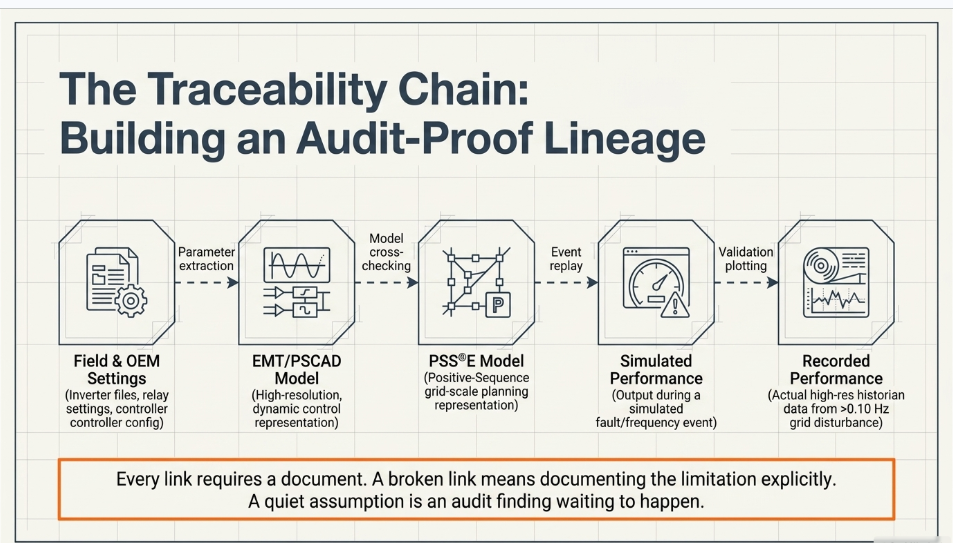
The output of a good verification program is a chain that an auditor can walk in either direction:
Field and OEM settings → PSCAD/EMT model → PSS®E positive-sequence model → simulated plant performance → recorded plant performance
Every link needs a document behind it. Where a link cannot be closed — usually because an OEM will not release a proprietary control parameter — the correct response is to document the limitation explicitly, not to quietly assume the model is right.
Part 6 Building an audit-ready evidence package
Compliance is not the analysis. Compliance is the evidence of the analysis, retained and retrievable.
A complete post-COD package generally contains:
- Applicability determination and the basis for it
- The TP/PC verification criteria obtained under MOD-026-2 R1
- Test plans, with dates and revision history
- Raw recorded data with time stamps and provenance
- Settings files as extracted, with extraction dates
- Firmware version evidence
- The model files as submitted, versioned
- Parameter comparison matrices with a source reference for every parameter
- Simulation output and comparison plots
- Attachment 2 for MOD-025, complete with the one-line diagram
- Transmittal evidence — dated proof of submittal inside the 90-day and 365-day windows
- Correspondence with the TP/PC, including review responses
- A register of open items, with owners and target dates
The last item is the one that distinguishes a mature program. Auditors are generally far more comfortable with an entity that has identified a gap, documented it, and is tracking it to closure than with an entity whose package is silent on a question it should have asked.
Case studies
The following are anonymized composites drawn from representative engagements. Facility names, owners, capacities and dates have been changed or generalized, and no confidential client information is disclosed.
Case study 1 The reactive capability that existed on paper only
Facility: approximately 200 MWac utility-scale solar PV, ERCOT, roughly nine months past COD.
Trigger: MOD-025 verification approaching the 12-month post-COD deadline.
What we found: the registration data and interconnection agreement reflected a reactive capability of roughly 0.95 leading and lagging at the point of interconnection. Verification testing established that the facility could reach the lagging requirement, but under-excited capability fell approximately 12 percent short of the registered figure at full real power output.
The hardware was not the constraint. Three separate limits were stacking: a conservative reactive limit configured in the plant controller during commissioning and never revisited; auxiliary and station service load that had not been accounted for in the original capability calculation; and an inverter-level reactive priority setting that reduced available reactive output at high active power.
What we did: documented the verified capability, prepared the Attachment 2 submittal against measured performance rather than the registered value, and issued a separate engineering recommendation identifying the plant controller limit as recoverable capability. The owner elected to revise the plant controller configuration, after which a follow-on verification demonstrated capability consistent with the interconnection agreement, and the RARF was updated.
Takeaway: at IBR facilities, reactive capability shortfalls are usually configuration problems, not equipment problems. They are also usually invisible until someone tests for them — and they can quietly affect both compliance and the plant's ability to meet its voltage schedule.
Case study 2 — Two models, one plant, two different answers
Facility: approximately 150 MW / 600 MWh battery energy storage system, ERCOT, first MOD-026 submittal after commissioning.
Trigger: post-commissioning model verification and validation.
What we found: the PSCAD model supplied with the project represented momentary cessation during low-voltage events. The firmware actually commissioned at site used continuous current injection through the ride-through region — a different, and considerably better, behavior. The positive-sequence model was a third variant, with voltage trip thresholds that matched neither the EMT model nor the protection settings loaded in the relays.
The mismatch had gone unnoticed because each model had been reviewed in isolation, by different parties, at different stages of the project.
What we did: established the as-commissioned configuration from inverter and PCS settings files and firmware version evidence, rebuilt the parameter set for both models from that single source, and validated against a recorded transmission fault captured by the facility's disturbance monitoring. The corrected EMT model reproduced the measured active and reactive power recovery closely; the original model had predicted a cessation and recovery ramp that never occurred.
Takeaway: the value of MOD-026 is not the paperwork. A model that predicts momentary cessation where the plant actually injects current will cause the Planning Coordinator to see a weaker, less helpful resource than you own — and can influence study outcomes and curtailment decisions for years.
Case study 3 — A protection setting that only the model knew about
Facility: approximately 300 MWdc solar PV, ERCOT, roughly four months past COD.
Trigger: combined model-to-settings verification performed alongside a ride-through review.
What we found: the positive-sequence model carried an undervoltage trip threshold consistent with the original design specification. The relays in service had been commissioned with a more sensitive setting, inside the region where the facility was required to ride through. Neither the EMT model nor the model quality test results had flagged it, because the EMT model represented the design value as well.
Because the plant had not yet experienced a qualifying disturbance, the discrepancy would not have surfaced through validation. It surfaced through parameter-by-parameter comparison between the relay settings files and the model.
What we did: documented the discrepancy, quantified the exposure against the applicable ride-through envelope, and issued a recommendation to bring the protection setting into conformance. The setting was revised, the models were updated to match, and the model verification submittal reflected the corrected configuration.
Takeaway: model validation against recorded events cannot find a defect the plant has not yet been exposed to. Parameter verification can. This is exactly why MOD-026 requires both, and why treating verification as a formality is a false economy.
Frequently Asked Questions — Earthing Types and Keentel Engineering Practice
The questions below are the ones we hear most often from clients, EPC design teams, and reviewing engineers when selecting and specifying earthing systems. The answers reflect Keentel Engineering's practice across utility, industrial, and renewable-generation grounding studies.

About the Author:
Sandip "Sonny" R. Patel, P.E.
IEEE Senior Member · Founder & CEO, Keentel Engineering
In 1995, Sonny Patel earned his Electrical Engineering degree from the University of Illinois. But degrees don't build legacies — action does.
For three decades, he has worked the power industry from every side of the table: 16 years as a utility engineer at Exelon/Commonwealth Edison; generation leadership across hydroelectric, industrial steam turbine, and a 9 GW renewable fleet; NERC Regional Entity Senior Compliance Engineer and Audit Team Lead, auditing some of the nation's largest utilities; and testing and commissioning lead on equipment up to 765 kV — the very top of the North American grid.Utility. Generator. Regulator. Consultant. Few engineers have seen all four seats. Fewer still have sat in them.
His experience spans nuclear, hydro, conventional generation, renewables, oil and gas, mining — and today's data centers, where he is authoring a three-book series on data center design. He is a Licensed Professional Engineer in six states and a Licensed Electrical Contractor in Florida (Unlimited EC) — he doesn't just design the work; he's qualified to stand behind its execution.Today, as Founder and CEO of Keentel Engineering, Sonny leads a nationwide team of engineers delivering substation design, power system studies, NERC compliance, and commissioning — done right, coast to coast.Three decades. Every side of the table. One standard: accountable engineering.
Services

Let's Discuss Your Project
Let's book a call to discuss your electrical engineering project that we can help you with.
About the Author:
Sandip "Sonny" R. Patel, P.E.
IEEE Senior Member · Founder & CEO, Keentel Engineering
In 1995, Sonny Patel earned his Electrical Engineering degree from the University of Illinois. But degrees don't build legacies — action does.
For three decades, he has worked the power industry from every side of the table: 16 years as a utility engineer at Exelon/Commonwealth Edison; generation leadership across hydroelectric, industrial steam turbine, and a 9 GW renewable fleet; NERC Regional Entity Senior Compliance Engineer and Audit Team Lead, auditing some of the nation's largest utilities; and testing and commissioning lead on equipment up to 765 kV — the very top of the North American grid.
Utility. Generator. Regulator. Consultant. Few engineers have seen all four seats. Fewer still have sat in them.
His experience spans nuclear, hydro, conventional generation, renewables, oil and gas, mining — and today's data centers, where he is authoring a three-book series on data center design. He is a Licensed Professional Engineer in six states and a Licensed Electrical Contractor in Florida (Unlimited EC) — he doesn't just design the work; he's qualified to stand behind its execution.
Today, as Founder and CEO of Keentel Engineering, Sonny leads a nationwide team of engineers delivering substation design, power system studies, NERC compliance, and commissioning — done right, coast to coast.Three decades. Every side of the table. One standard: accountable engineering.
Leave a Comment
Thank you for contacting us.
We will get back to you as soon as possible.
We will get back to you as soon as possible.
Oops, there was an error sending your message.
Please try again later.
Please try again later.
Related Posts

By SANDIP R PATEL
•
September 30, 2026
Learn NERC and ERCOT compliance requirements for natural gas power plants, including GO/GOP obligations, O&P standards, GADS reporting, and audits.

By SANDIP R PATEL
•
September 26, 2026
Learn how to prepare a MISO large-load interconnection package, including PSS®E models, BESS smoothing, harmonic data and transmission-owner requirements.

By SANDIP R PATEL
•
September 26, 2026
Learn where storage belongs in an 800 VDC AI data center, including capacitors, flywheels, BESS, fault current, protection, grounding, and EMT design.

By SANDIP R PATEL
•
September 26, 2026
Learn how SPP’s HILL and HILLGA framework works for large-load projects, including studies, BTM generation, modeling, EMT requirements, and firm service.

By SANDIP R PATEL
•
September 25, 2026
Learn how IBR time synchronization, IEEE 2800, IRIG-B verification, and PTP solutions help meet disturbance monitoring compliance requirements.

By SANDIP R PATEL
•
September 24, 2026
Learn why continuing technical training matters in power engineering, including standards, software skills, PDH requirements, and career growth.
By SANDIP R PATEL
•
September 22, 2026
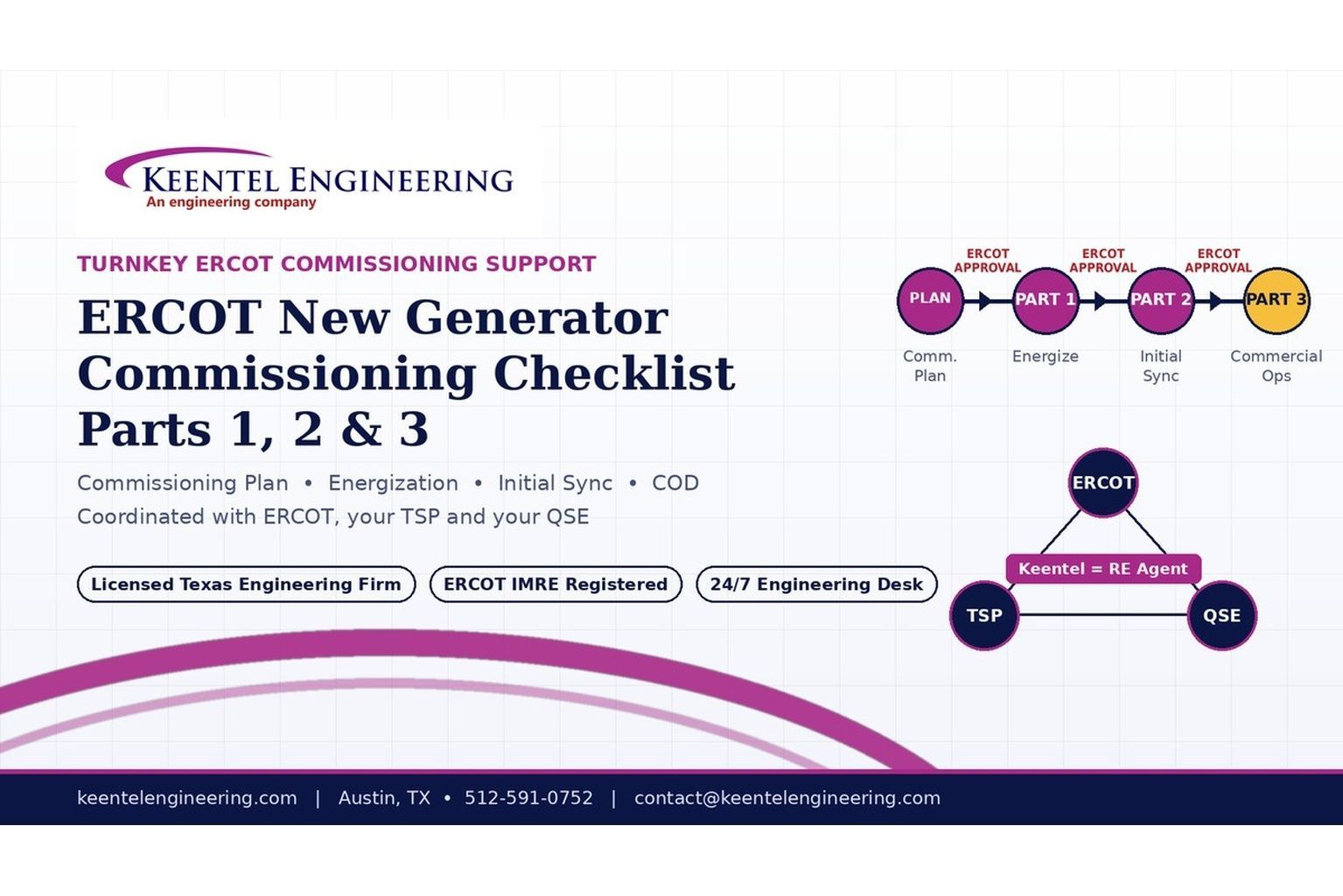
2026 ERCOT commissioning guide covering the Commissioning Plan, Checklist Parts 1–3, BESS requirements, TSP/QSE coordination, field testing and COD.

By SANDIP R PATEL
•
September 22, 2026
Learn PRC-030-1 R1 event detection requirements for inverter-based resources, SEL platforms, disturbance monitoring, and audit-ready compliance.
By SANDIP R PATEL
•
September 22, 2026
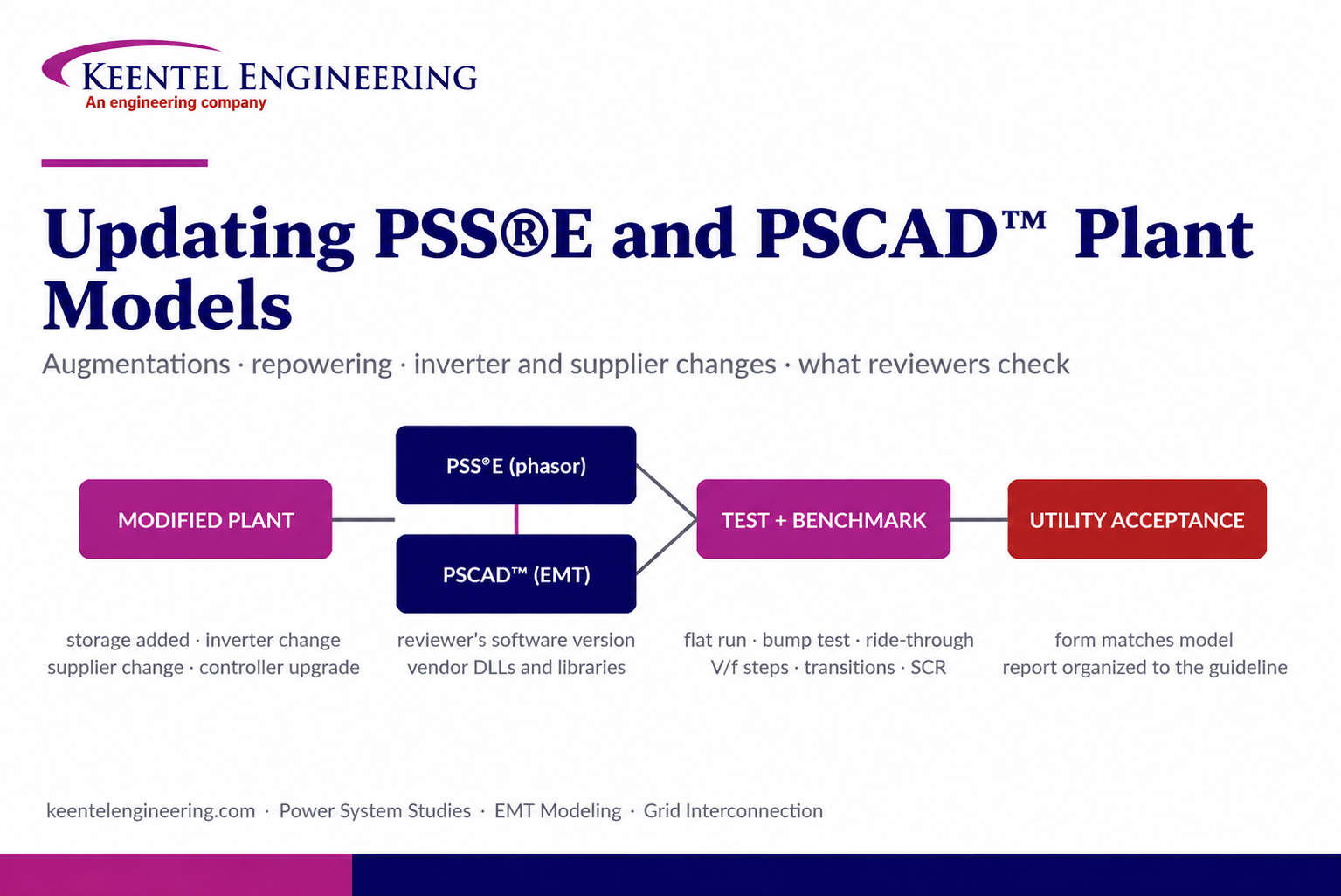
Learn how PSS®E and PSCAD™ model updates support plant augmentations, repowering, equipment changes, testing, benchmarking, and grid compliance.





