
A Coordinated Electric System Interconnection Review—the utility’s deep-dive on technical and cost impacts of your project.
Challenge: Frequent false tripping using conventional electromechanical relays
Solution: SEL-487E integration with multi-terminal differential protection and dynamic inrush restraint
Result: 90% reduction in false trips, saving over $250,000 in downtime
The three operating regions you have to design to
| Device | Output vs voltage | Response | Best suited to | Main limitations |
|---|---|---|---|---|
| Mechanically switched capacitor or reactor | Proportional to voltage squared | Seconds; discrete steps; limited switching operations per day | Steady-state reactive supply, voltage profile, loss reduction | No dynamic capability; step voltage change on switching; capability collapses when most needed |
| Static var compensator | Capacitive branches proportional to voltage squared | A few cycles; continuously controllable | Continuous control where cost matters and deep voltage support is not the driver | Square-law capability loss; harmonic filters are part of the plant and interact with the network |
| STATCOM | Approximately proportional to voltage — constant current capability | One to two cycles closed loop; converter response faster still | Voltage stability margin, weak interconnections, fast disturbance recovery, flicker and unbalance compensation | Higher capital cost; converter losses; adds a converter and its control dynamics to the network |
| Synchronous condenser | Governed by machine capability and excitation | Excitation response in the hundreds of milliseconds; inherent inertial response instantaneous | System strength and inertia, short-circuit contribution, black start support | Rotating plant with maintenance and losses; slower controlled response than a converter |
| STATCOM with energy storage | Reactive as a STATCOM, plus real power within the storage rating | As STATCOM for reactive; real power limited by storage | Where a real power deficiency is part of the problem | Cost and complexity of the storage; different failure and maintenance profile |
| Stage | Keentel scope | Outcome |
|---|---|---|
| Screening | Series-compensation proximity, radial contingency review, UIF and short-circuit ratio screening, frequency scans | Early identification of which SSO types apply |
| Detailed studies | PSCAD/EMTDC EMT studies with vendor real-code models, impedance-based and frequency-scan analysis | Clear evidence of stability margins or risk |
| Model quality | EMT model review, benchmarking against positive-sequence models, model acceptance support | Models that system operators accept |
| Mitigation | Control retuning recommendations with vendors, SSDC and bypass logic requirements, protection and monitoring specifications | Practical, coordinated solutions |
| Interconnection support | SSR and SSO study reports for ISO and utility requirements, response to reviewer comments | Fewer delays in the interconnection process |
Resilience: designing CDUs to the facility Tier objective
Liquid cooling makes heat removal more critical, not less. Cold plates hold only seconds of thermal buffer. If TCS flow stops, processors throttle or shut down very quickly. Resilience design must therefore cover:
- Pump redundancy: N+1 pumps at minimum, with automatic changeover.
- CDU redundancy: N+1 CDUs on a common TCS header, or 2N CDUs serving A and B manifolds for fault-tolerant designs.
- Power to CDUs: dual-corded CDUs fed from A and B sources, with pumps and controls on UPS power so coolant keeps flowing through a utility failure and generator start. This is the liquid-cooling equivalent of continuous cooling.
- Facility water continuity: chilled water or condenser water must also continue, through thermal storage, UPS-backed pumps or a high enough FWS temperature that the TCS can coast on stored thermal mass for the transfer period.
- Concurrent maintainability: isolation valves so any CDU, pump, filter or manifold section can be serviced without stopping the others.
- Leak management: leak detection, drip trays, automatic isolation valves and procedures for fluid spills.
Electrical engineering considerations
CDUs and liquid-cooling plants are electrical loads with their own design requirements:
- Pump motors and VFDs. Large CDUs use variable-frequency drives on their pump motors. These introduce harmonic current that must be included in the facility's harmonic study and IEEE 519 evaluation.
- Critical mechanical load on UPS. Putting CDU pumps on UPS increases UPS and battery sizing. The mechanical UPS load must be included in redundancy and ride-through calculations.
- Feeder and protection design. Dual feeds, automatic transfer, selective coordination and arc-flash labelling apply to CDU power distribution just as they do to IT power.
- Generator transient response. CDU pumps restarting together after a transfer create motor inrush on the generators. Staged restarts and soft acceleration reduce the step load.
- Load dynamics. AI training loads can swing rapidly between high and low power. Cooling controls must track those swings without temperature overshoot, and electrical systems must handle both the IT and the cooling load changes.
Commissioning a liquid-cooled data hall
- Flush and clean the TCS piping and manifolds to the specified cleanliness, using high-purity flush water.
- Fill and vent with the specified coolant, verifying glycol concentration and chemistry.
- Pressure test for leaks at design and test pressures, including quick-disconnect fittings.
- Verify sensors and controls: flow meters, temperature sensors, pressure transmitters, leak detection and BMS points.
- Load test with heat load banks connected through the cold-plate interfaces or rack manifolds, across the operating range.
- Prove the heat balance on both loops at several load steps, and the approach temperature against the design.
- Test failure scenarios: pump failure, CDU failure, power transfer to generator, valve failure and loss of facility water, confirming temperatures stay within the IT vendor's limits.
How Keentel Engineering helps
Keentel Engineering supports data center owners, developers and EPCs with the electrical engineering that liquid-cooled facilities depend on, and coordinates with the mechanical engineer of record and cooling vendors on the integrated design.
String Inverter vs Central Inverter: An Engineering Guide for US Utility-Scale Solar
October 10, 2026 | Blog
Part A — String vs Central Inverters at a Glance
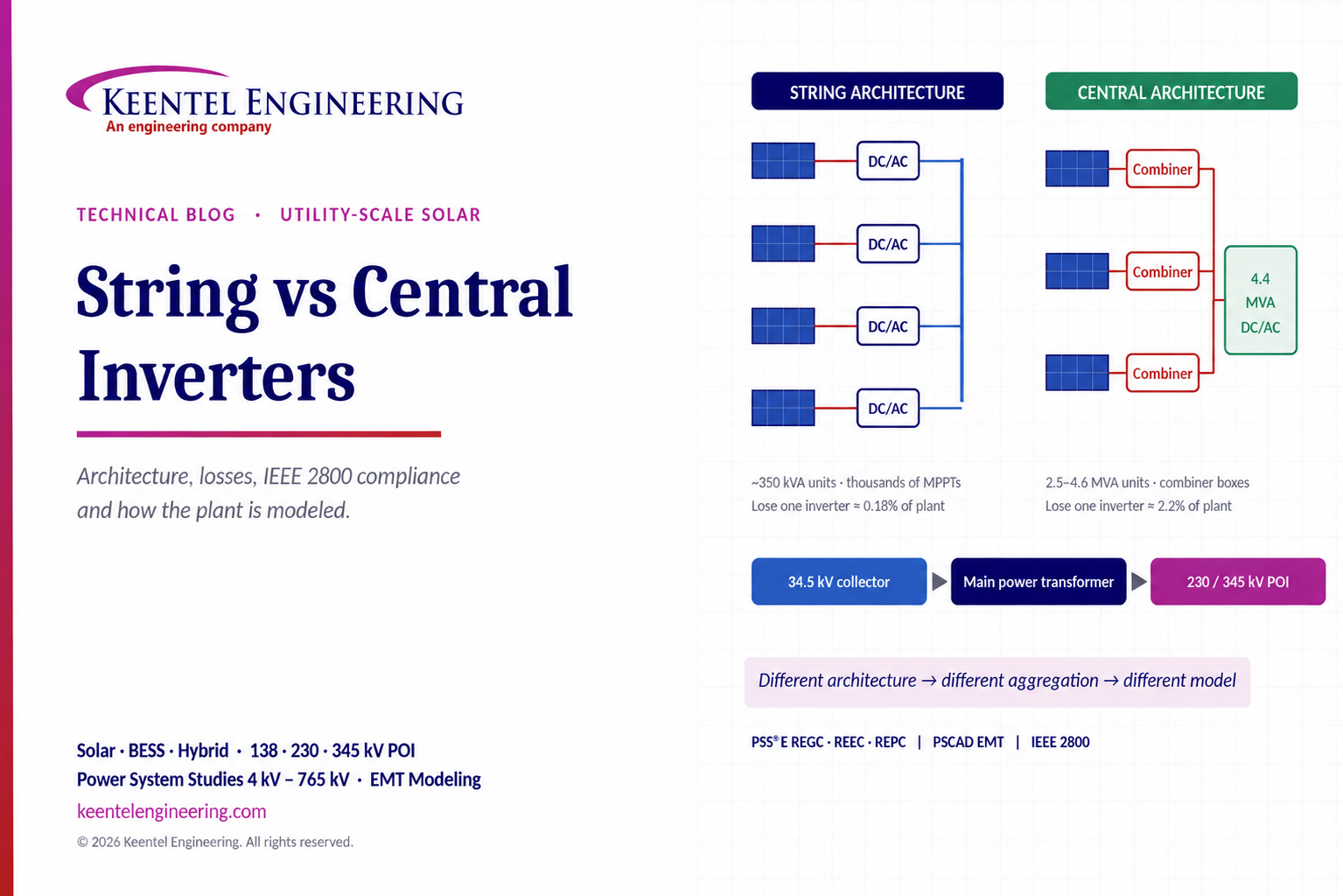
Every inverter in a utility-scale solar plant does the same basic job: it converts DC power from the PV array into grid-synchronized AC power. How the plant is divided among inverters changes much more than equipment count. It changes DC and AC cabling, energy yield, availability, maintenance, protection, reactive power capability, harmonic behavior and, critically, how the plant is represented in interconnection studies.
Two architectures, one job
| Feature | String inverter architecture | Central inverter architecture |
|---|---|---|
| How PV is connected | A small number of strings connect directly to each inverter | Many strings are combined in DC combiner boxes and fed to one high-power inverter |
| Typical unit rating (utility-scale) | About 250 to 350 kVA per inverter | String Inverter vs Central Inverter: An Engineering Guide for US Utility-Scale Solar |
| Typical AC output voltage | 600 to 800 Vac, collected on LV AC busbars | 550 to 690 Vac, directly into a dedicated step-up transformer |
| MPPT granularity | Many MPPT trackers per unit; thousands across the plant | One to a few MPPT trackers per unit |
| DC cabling | Short DC runs; more LV AC cabling | Long 1,500 Vdc homeruns and combiner boxes |
| Loss of one unit | About 0.18% of a 200 MWac plant | About 2.2% of a 200 MWac plant |
| Maintenance model | Swap-out replacement by a two-person crew | Component-level repair by specialist technicians |
| Unit count for 200 MWac | About 650 inverters | About 50 inverters |
The important point
The choice is not simply "string = small plant, central = large plant." Many of the largest US solar plants use string inverters, and central inverters remain competitive on large, flat, uniform sites. The right choice depends on:
- Plant size and layout: terrain, block shape and distance from array to collection point.
- Losses: DC versus AC cable losses, mismatch losses and transformer losses.
- Maintenance and availability: spare strategy, repair time and access.
- Redundancy: how much generation is lost when a single unit trips.
- MPPT requirements: shading, uneven terrain, mixed orientations and bifacial gain.
- Grid requirements: IEEE 2800-2022 performance, reactive capability at the point of interconnection and ride-through.
- Project economics: equipment, balance of system, construction and lifetime O&M cost.
The inverter is not just a DC-to-AC converter. It is the component that determines how a renewable plant behaves on the grid — and how that behavior must be modeled.
Part B — String Inverter vs Central Inverter: An Engineering Guide for US Utility-Scale Solar
Utility-scale PV in the US is typically built as a 1,500 Vdc array, collected at 34.5 kV through pad-mounted or skid-mounted step-up transformers, and connected through a project substation to the transmission system at 115, 138, 161, 230, 345 or 500 kV. Within that framework, the inverter architecture decision affects nearly every engineering discipline on the project. This guide explains the differences from the array to the point of interconnection (POI), and from the design table to the PSS®E and PSCAD™ study models.
How each architecture is built
String inverter architecture
Each string inverter accepts a limited number of PV strings, commonly 18 to 30 strings across 6 to 12 MPPT inputs. Inverters are distributed through the array, mounted on racking posts or small frames, and their AC outputs are collected by LV AC cables to an AC combiner or directly to the low-voltage bus of a 34.5 kV pad-mounted transformer. A typical block groups 15 to 20 inverters onto one 5 to 7 MVA transformer.
- DC side: short string cables run from modules to the nearest inverter; DC combiner boxes are usually not required.
- AC side: many LV AC circuits at 600 to 800 Vac feed each transformer.
- Control: each inverter performs its own MPPT and current control; the plant controller dispatches active and reactive power to hundreds of units over a communications network.
Central inverter architecture
Strings are paralleled in DC combiner boxes, typically 16 to 32 strings per box with string fuses and a disconnect. DC feeders from the combiners run to a central inverter station, usually a factory-integrated skid with the inverter, the MV step-up transformer, MV switchgear and auxiliary power.
- DC side: combiner boxes, string fusing and long 1,500 Vdc feeders.
- AC side: the inverter connects directly to its own transformer winding, with very short LV AC connections.
- Control: each unit tracks one to a few maximum power points over a large array section.
US voltage classes and where the inverter sits
| Level | Typical US voltage | Equipment |
|---|---|---|
| PV array (DC) | Up to 1,500 Vdc | Modules, string cables, combiners (central) |
| Inverter AC output | 550 to 800 Vac | String or central inverters |
| Collection system | 34.5 kV (sometimes 13.8 or 24.9 kV on smaller plants) | Pad-mount or skid transformers, underground feeders, collector breakers |
| Interconnection | 115, 138, 161, 230, 345 or 500 kV | Main power transformer(s), POI breaker, metering |
The 34.5 kV collection system and the main power transformer are common to both architectures. The differences are concentrated at the array and the inverter block, but their effects reach the POI.
DC/AC ratio and clipping
Both architectures oversize the DC array relative to inverter AC capacity to raise energy yield and capacity factor:
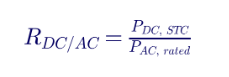
US utility-scale plants commonly use ratios between about 1.25 and 1.40. Higher ratios increase clipping during peak irradiance but raise output in the morning, evening and on cloudy days. String inverters allow the ratio to be adjusted finely block by block, which is useful on irregular sites. Central inverters apply one ratio across a large array section, which is efficient on uniform layouts. In both cases the ratio interacts with energy storage: clipped energy on DC-coupled hybrid plants can be captured by batteries.
MPPT granularity, mismatch and terrain
The maximum power point tracker finds the operating voltage that extracts the most power from the strings connected to it. When strings under one tracker see different conditions shading, soiling, different tilt on rolling terrain, module degradation or bifacial rear-side irradiance differences the shared operating point cannot be optimal for all of them. This is mismatch loss.
- String inverters track each small group of strings independently, so mismatch is contained within a few strings.
- Central inverters track a large array section at one operating point, so non-uniformity is averaged across hundreds of strings.
On flat, uniform sites with single-axis trackers, the yield difference is usually small. On rolling terrain, sites with partial shading, mixed tracker rows or uneven bifacial conditions, finer MPPT granularity can recover meaningful energy. The benefit must be quantified with a site-specific energy model rather than assumed.
Losses: DC, AC and transformer
Conductor losses in each part of the plant follow the familiar relationship:
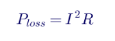
At the same power, a 1,500 Vdc circuit carries less current than an 800 Vac three-phase circuit, but the comparison depends on cable lengths and sizes. In practice:
- Central architectures have longer DC feeders from combiners to the inverter station, but very short LV AC runs.
- String architectures have short DC runs but many LV AC circuits from distributed inverters to the transformer.
- Transformer losses depend on the number, size and loading of step-up transformers; string blocks often use more, smaller transformers or multi-winding units.
- Night-time losses: transformer no-load losses and inverter standby consumption accrue every night and matter in lifetime energy and auxiliary load calculations.
A complete loss model compares the full chain from module to POI for both options, including the main power transformer and collector system losses.
Availability and redundancy
When a single inverter trips, the generation lost is proportional to its share of the plant:
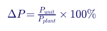
For a 200 MWac plant, losing a 350 kVA string inverter removes about 0.18% of output; losing a 4.4 MVA central inverter removes about 2.2%. String plants therefore degrade gracefully, but they have many more units that can fail. Central plants have fewer, larger failures, so repair time and spare-parts strategy dominate availability. A fair comparison uses failure rates, mean time to repair and the replacement strategy for each option over the project life.
Operations and maintenance
| Topic | String architecture | Central architecture |
|---|---|---|
| Typical repair | Replace the whole inverter with a spare | Replace power modules, fans, boards or filters on site |
| Skills required | General electrical technicians | Factory-trained specialists for MV and power electronics |
| Spares | Stock of complete spare inverters | Critical component kit; long lead times for major parts |
| Monitoring | Hundreds of devices; strong communications design needed | Fewer devices; string monitoring at combiners |
| Long-term replacement | Gradual replacement as units fail | Major mid-life refurbishment or replacement events |
| Arc-flash exposure | Lower energy at each LV point, but many points | Higher-energy MV and DC equipment at each station |
Protection and the National Electrical Code
Utility-scale PV in the US is designed to NFPA 70 (National Electrical Code), primarily Article 690, and Article 691 for large-scale PV electric supply stations of 5 MWac and above under engineered design and supervision.
- DC overcurrent: central architectures fuse each string in the combiner box. String inverters with one or two strings per MPPT input often do not need string fuses, because the available backfeed current is below the module's maximum series fuse rating.
- DC arc-fault protection: Article 690 requires arc-fault protection for many PV DC circuits; Article 691 allows engineered alternatives for large-scale plants. Inverter and combiner arc-detection capability should be confirmed early.
- Ground-fault detection: each inverter monitors its own DC array insulation; central inverters monitor a much larger array, which can make insulation faults harder to locate.
- AC protection: string blocks require coordinated LV breakers or fuses for many circuits; central skids rely on integrated LV and MV protection.
- Collector and substation protection: both architectures contribute limited fault current, so feeder and transformer protection must be set for inverter-based resource (IBR) behavior rather than synchronous machine behavior.
Reactive power and voltage control
IEEE 2800-2022 and most US interconnection requirements specify
reactive capability at the POI, not at the inverter terminals. A common requirement is the ability to operate at 0.95 power factor leading or lagging at rated active power:

For a 200 MW plant, this is about 66 Mvar at the POI. The inverters must also supply the reactive losses of the step-up transformers, the 34.5 kV collector cables (partly offset by cable charging), and the main power transformer, while staying within their own voltage limits. Both architectures can meet the requirement, but the margin is set differently:
- String plants add capability in small increments by adding inverters, and spread reactive output across hundreds of units.
- Central plants add capability in large steps; a shortfall may require an additional skid, a shunt capacitor bank, or a STATCOM.
- Voltage at the inverter terminals rises during reactive output and can limit capability, particularly at high grid voltage. This must be checked across the full operating range, not only at nominal voltage.
Grid performance: IEEE 2800 and NERC
US transmission-connected plants are increasingly specified to IEEE 2800-2022, which defines performance at the reference point of applicability (usually the POI or point of measurement). NERC's reliability standards for IBRs developed under FERC Order No. 901, including PRC-029-1 for voltage and frequency ride-through, apply to the plant regardless of inverter architecture.
The architecture affects how the plant achieves compliance:
- Ride-through: every inverter in the plant must ride through the same event. A string plant has hundreds of protection relays and firmware instances, so consistent settings and firmware management are critical. Several NERC disturbance reviews have found plant output losses caused by inverter-level settings rather than the grid event itself.
- Momentary cessation: IEEE 2800 effectively prohibits momentary cessation within the continuous and mandatory operation regions, so inverter firmware must be configured accordingly.
- Fast fault current: IBR fault current is limited to roughly 1.0 to 1.5 times rated current and is controlled by firmware. Positive- and negative-sequence injection during unbalanced faults depends on the inverter model.
- Active power–frequency response: primary frequency response and fast frequency response are commanded by the plant controller and executed by each inverter.
How inverter architecture changes the study model
From a grid-study perspective, the inverter type affects how the plant and its controls are represented in tools such as PSS®E and PSCAD™.
Positive-sequence (PSS®E, PSLF) models
US planning models represent a solar plant as one or a few equivalent generators using the WECC generic renewable energy system models:
- REGC: the generator/converter model, representing the inverter current injection and its limits.
- REEC: the electrical control model, representing inverter-level active and reactive control.
- REPC: the plant controller model, representing POI voltage, reactive power and frequency control.
The single-machine equivalent includes an equivalent pad-mount transformer and an equivalent collector system impedance. The equivalent collector impedance is not the sum of the feeder impedances. A common approach weights each collector segment by the square of the number of inverters it carries:
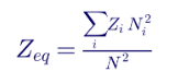
where Zi is the impedance of segment i, Ni is the number of inverters downstream of that segment, and N is the total number of inverters on the feeder. For example, a feeder with six blocks connected by equal segments of impedance z has an equivalent of z × (1² + 2² + … + 6²) ÷ 6² = 2.53 z, not 6 z.
Architecture-specific considerations include:
- String plants: hundreds of inverters are aggregated into one equivalent. Inverter-level controls are usually simple and fast, and the plant controller does most of the voltage regulation. Parameters must reflect the actual inverter firmware, communications latency and the plant controller's dispatch method.
- Central plants: fewer, larger units; aggregation is simpler, and some studies model multiple equivalents by feeder. Inverter-level voltage control may play a larger role.
- Mixed plants: different inverter models or firmware versions in the same plant may need separate equivalent generators.
EMT (PSCAD) models
Electromagnetic transient studies require vendor-specific, validated models that represent the actual control code. These are increasingly required by transmission providers and ISOs/RTOs for weak-grid areas, ride-through verification, control interactions and subsynchronous oscillation screening. For string plants, the vendor model is usually scaled to represent many inverters; aggregation must preserve the plant's dynamic response, phase-locked-loop behavior and current limits.
Short-circuit and harmonic models
- Short circuit: IBRs are represented as controlled current sources or with vendor-specified fault current tables, not with synchronous machine subtransient reactances.
- Harmonics and resonance: the 34.5 kV collector system's cable capacitance, the transformer inductances and the inverters' output filters form resonant circuits. Many string inverters can shift resonance frequencies relative to a few large central units, and inverter control bandwidth affects harmonic damping. IEEE 519 limits at the POI must be verified with a harmonic impedance model.
Different architecture means different plant aggregation, which means different control behavior in the model. The study is only as good as the equivalent.
System strength and weak-grid performance
Short-circuit ratio (SCR) at the POI indicates how strong the grid is relative to the plant:

At low SCR, typically below about 3, IBR plants are more prone to control instability, voltage oscillations and ride-through problems. Both architectures can be designed for weak grids, but the inverter's phase-locked loop, current-control tuning and plant controller gains must be verified with EMT studies. Grid-forming inverters, now offered in both string and central formats, are an emerging option for very weak systems.
Worked comparison: a 200 MWac plant at a 230 kV POI
The following illustrative comparison shows how the two architectures differ for the same plant.
| Parameter | String architecture | Central architecture |
|---|---|---|
| Plant rating at POI | 200 MWac | 200 MWac |
| DC array (DC/AC ≈ 1.30) | ≈ 260 MWdc, ≈ 16,000 strings | ≈ 260 MWdc, ≈ 16,000 strings |
| Inverter rating | 352 kVA | 4.4 MVA |
| Inverters installed | 648 (36 blocks × 18) | 52 |
| Total inverter capacity | ≈ 228 MVA | ≈ 229 MVA |
| Step-up transformers | 36 × 6.3 MVA, 34.5 kV | 52 × 4.4 MVA, 34.5 kV (integrated skids) |
| MPPT trackers | ≈ 5,800 | ≈ 100 to 200 |
| DC combiner boxes | None | ≈ 600 to 1,000 |
| Generation lost per inverter trip | ≈ 0.18% | ≈ 2.2% |
| POI reactive requirement at 0.95 PF | ≈ 66 Mvar | ≈ 66 Mvar |
| PSS®E representation | One or more REGC/REEC/REPC equivalents with collector equivalencing | One or more REGC/REEC/REPC equivalents with collector equivalencing |
Both options can meet the same interconnection requirements. The decision depends on site terrain, energy model results, balance-of-system cost, the owner's O&M model, equipment lead times, and the interconnection study results.
Hybrid plants and energy storage
Many US solar projects now include battery energy storage. Architecture affects the coupling options:
- AC-coupled storage: batteries have their own inverters and connect to the 34.5 kV collector system; this works with either PV architecture.
- DC-coupled storage: DC-DC converters connect batteries to the PV inverter's DC bus. This is common with central inverters and can capture clipped energy, but it ties PV and storage control together.
- Interconnection limits: the plant controller must enforce the POI export limit and coordinate PV and storage dispatch, which must be modeled in the REPC or a hybrid plant controller model.
A decision checklist
- Site layout: flat and uniform, or rolling terrain with irregular block shapes?
- Energy yield: site-specific energy model with mismatch, clipping, and DC and AC losses.
- Balance of system: DC combiners and feeders versus LV AC cabling and more transformers.
- Grid requirements: IEEE 2800, ISO/RTO and transmission owner requirements, reactive capability at the POI and weak-grid performance.
- Model availability: validated PSS®E and PSCAD models for the exact inverter and firmware.
- O&M strategy: in-house crews or OEM service agreement, spare strategy and access.
- Supply chain: lead times, domestic content and warranty terms.
- Lifecycle: mid-life replacement, repowering and future storage integration.
How Keentel Engineering helps
Keentel Engineering supports solar, storage and hybrid projects from early design through interconnection and commissioning, with
power system studies from 4 kV to 765 kV.
| Stage | Keentel scope | Outcome |
|---|---|---|
| Architecture evaluation | String versus central comparison: losses, reactive capability, protection and grid compliance | An informed architecture decision |
| Collection system design | 34.5 kV collector layout, cable sizing, grounding, transformer specification | Efficient, protected collection systems |
| Interconnection studies | Load flow, short circuit, dynamic stability, reactive capability and IEEE 2800 assessments | Studies accepted by the transmission provider |
| Modeling | PSS®E single-machine equivalents, collector equivalencing, PSCAD EMT model integration and validation | Models that match how the plant actually behaves |
| Power quality | Harmonic and resonance studies to IEEE 519 | Compliant harmonic performance at the POI |
| Protection and NERC compliance | Relay settings, ride-through verification and NERC model validation support | Reliable operation and compliance |
Choosing an inverter architecture or preparing interconnection models? Talk to Keentel Engineering at (813) 389-7871, contact@keentelengineering.com, or book a 15-minute scoping call at calendly.com/keentel-engineering/15min.
Part C — Case Studies
The following are illustrative scenarios based on conditions typical of US utility-scale solar projects. They show how Keentel Engineering approaches architecture, modeling and grid-performance problems; site details are generalised and figures are rounded.
Case Study 1 — 150 MWac string inverter plant at a weak 138 kV POI
Situation
A developer plans a 150 MWac string inverter plant on rolling terrain with 470 inverters on a 34.5 kV collector system. The 138 kV POI has an SCR of about 2.8 under N-1 conditions. The transmission provider's initial dynamic study shows poorly damped voltage oscillations after nearby faults.
Analysis
Review of the PSS®E model shows two problems. The equivalent collector impedance was calculated as a simple series sum, overstating the impedance by more than double. The plant controller gains were vendor defaults intended for a strong grid. EMT simulation with the vendor PSCAD model confirms that the oscillation is driven by plant controller tuning, not by the inverters.
Engineered solution
Keentel recalculates the collector equivalent using the power-weighted method, retunes the plant controller voltage control gains and time constants, and verifies the settings across N-1 SCR conditions with EMT simulation.
Outcome
The revised model shows well-damped response for all study contingencies, and the corrected settings are carried into the commissioning plan and model validation.
Case Study 2 — 250 MWac central inverter plant: reactive capability at a 230 kV POI
Situation
A 250 MWac central inverter plant on a flat agricultural site connects at 230 kV. The design uses 58 central inverters at 0.95 power factor capability measured at the inverter terminals. The interconnection agreement requires 0.95 power factor at the POI.
Analysis
A reactive capability study shows that, after transformer and collector reactive losses, the plant can deliver only about 70% of the required lagging reactive power at the POI at full output. At high POI voltage, inverter terminal voltage limits reduce capability further.
Engineered solution
Keentel evaluates three options: additional central inverter skids, a switched capacitor bank at 34.5 kV, and a main power transformer tap change. The selected solution combines a revised tap position with two additional skids, which also increase the DC/AC flexibility of the plant.
Outcome
The plant meets the full ±0.95 power factor requirement across the specified POI voltage range, with documented capability curves for the transmission provider.
Case Study 3 — 120 MWac string plant: collector system harmonic resonance at 138 kV
Situation
A 120 MWac string inverter plant with a long underground 34.5 kV collector system connects to a 138 kV system with nearby capacitor banks. The transmission owner requires a harmonic study to IEEE 519 before energization.
Analysis
Frequency scan studies show a parallel resonance near the 11th harmonic formed by collector cable capacitance, the capacitor banks and system inductance. Background voltage distortion at that frequency could be amplified at the POI.
Engineered solution
Keentel models the plant harmonic impedance using inverter vendor data, evaluates detuning options and coordinates inverter active damping settings with the vendor. A study of capacitor bank switching states identifies the worst-case conditions.
Outcome
With the revised inverter settings and a defined capacitor operating procedure, predicted harmonic distortion at the POI is within IEEE 519 limits, and post-energization measurements are planned to confirm performance.
Part D — Technical FAQ: String vs Central Inverters
1. What is the basic difference between string and central inverters?
Both convert DC to AC. String inverters connect a small number of PV strings to each unit and are distributed through the array. Central inverters combine many strings through DC combiner boxes into a single high-power unit, usually in a skid with the step-up transformer.
2. Are string inverters only for small plants?
No. Many large US utility-scale plants, including plants of several hundred megawatts, use string inverters. The decision depends on layout, losses, O&M strategy, grid requirements and economics, not just plant size.
3. What are typical utility-scale inverter ratings?
Utility-scale string inverters are commonly about 250 to 350 kVA with 600 to 800 Vac outputs. Central inverters are commonly about 2.5 to 4.6 MVA with outputs around 550 to 690 Vac. Ratings continue to increase as manufacturers release new products.
4. Which architecture gives higher energy yield?
On flat, uniform sites the difference is usually small. On rolling terrain, partially shaded or irregular sites, the finer MPPT granularity of string inverters can recover mismatch losses. The answer should come from a site-specific energy model that includes mismatch, clipping and all DC and AC losses.
5. How does MPPT granularity affect performance?
Each MPPT tracker can operate only one set of strings at one voltage. When the strings it controls see different irradiance, temperature or tilt, the shared operating point cannot be optimal for all of them. More trackers reduce this mismatch.
6. What is DC/AC ratio, and does it differ between architectures?
DC/AC ratio is the DC array capacity at standard test conditions divided by inverter AC rating. US utility-scale plants typically use 1.25 to 1.40. String architectures allow fine adjustment by block, while central architectures apply a ratio across larger sections.
7. Which architecture has better availability?
A single string inverter failure removes a very small share of output, while a central inverter failure removes a larger block. However, string plants have many more units. Lifetime availability depends on failure rates, repair time, spare strategy and service agreements.
8. How do the two architectures differ in maintenance?
String inverters are typically replaced as complete units by general technicians. Central inverters are repaired at component level by trained specialists, and major spare parts can have long lead times.
9. What NEC articles apply to utility-scale PV inverters?
NFPA 70 Article 690 covers PV systems, including DC circuit requirements, overcurrent protection, arc-fault and ground-fault protection. Article 691 covers large-scale PV electric supply stations of 5 MWac and above designed under qualified engineering supervision, and permits engineered alternatives to some Article 690 requirements.
10. Do string inverters need string fuses?
Often not. When only one or two strings connect to each MPPT input, the possible backfeed current is usually below the module's maximum series fuse rating. Central architectures fuse each string in the combiner box. The requirement must be verified for the actual module and inverter combination.
11. Where is reactive power capability measured?
IEEE 2800-2022 and most US interconnection requirements specify reactive capability at the POI or reference point of applicability, not at the inverter terminals. Inverters must supply the plant's internal reactive losses in addition to the POI requirement.
12. How much reactive capability does a 200 MW plant need?
At 0.95 power factor leading and lagging at rated output, the POI requirement is about 0.329 × 200 MW, or about 66 Mvar in each direction. Actual inverter capability must be higher to cover transformer and collector losses and voltage limits.
13. Does inverter architecture affect IEEE 2800 compliance?
Both architectures can comply. The difference is in how compliance is achieved and verified: string plants have hundreds of inverters whose settings and firmware must all be consistent, while central plants rely on fewer, larger units whose individual behavior has a greater effect on plant performance.
14. How are solar plants modeled in PSS®E?
US planning models typically represent the plant as one or more equivalent generators using the WECC generic models: REGC for the converter, REEC for electrical controls, and REPC for the plant controller. The equivalent includes a pad-mount transformer equivalent and an equivalent collector impedance.
15. Why is the collector system equivalent important?
The collector impedance affects voltage at the inverter terminals, reactive losses and plant dynamic response. Summing feeder impedances overstates the equivalent impedance. Weighting each segment by the square of the power or inverter count it carries gives a more accurate result.
16. When are EMT models required?
Transmission providers increasingly require EMT models for weak-grid areas, ride-through verification, control interaction studies and subsynchronous oscillation screening. These models must be vendor-specific, represent the actual control code and be validated against tests.
17. How much fault current do inverters contribute?
Inverter-based resources contribute limited, controlled fault current, typically about 1.0 to 1.5 times rated current. The amount and its positive- and negative-sequence content depend on inverter firmware. Protection settings must account for this behavior.
18. Does architecture affect harmonic performance?
Yes. The number and type of inverters, their output filters and control bandwidth, and the collector cable capacitance all affect harmonic emission and resonance. A harmonic study to IEEE 519 should use vendor harmonic data and a frequency-dependent model of the collector system and grid.
19. Which architecture is better for adding battery storage?
AC-coupled storage works with either architecture. DC-coupled storage is more common with central inverters and can capture clipped energy, but it links PV and storage control and must be modeled as a hybrid plant.
20. What is the most common mistake in choosing an inverter architecture?
Treating it purely as an equipment price decision. The architecture affects energy yield, balance of system, protection, reactive capability, harmonics, O&M and interconnection modeling. Evaluating all of these early avoids costly changes after the interconnection study or during commissioning.
References and Further Reading
Links were current at publication (October 2026).
- IEEE Std 2800-2022, Standard for Interconnection and Interoperability of Inverter-Based Resources Interconnecting with Associated Transmission Electric Power Systems. IEEE.
- IEEE Std 519-2022, Standard for Harmonic Control in Electric Power Systems. IEEE.
- NFPA 70, National Electrical Code, Articles 690 and 691. National Fire Protection Association.
- NERC Reliability Standard PRC-029-1, Frequency and Voltage Ride-through Requirements for Inverter-Based Resources, and Technical Rationale. North American Electric Reliability Corporation.
- WECC Second Generation Generic Renewable Energy System Models — Summary. Western Electricity Coordinating Council.
- Generic Models for PV Plants. Energy Systems Integration Group.
Disclaimer
This article is general technical information for educational purposes. It is not engineering advice for any specific project and does not create a professional relationship. Inverter ratings, unit counts, losses, reactive requirements and other values are illustrative; actual designs must follow the current editions of applicable codes and standards, transmission provider and ISO/RTO requirements, equipment manufacturer data and project-specific engineering analysis, sealed by a licensed professional engineer where required. Verify the current edition of any standard before relying on it.
Case studies are illustrative scenarios based on typical project conditions, not records of specific client projects. Figures are rounded and indicative.
IEEE, NERC, WECC, NFPA, PSS®E, PSCAD™ and other names are the property of their respective owners. Keentel Engineering is not affiliated with or endorsed by these organisations or any software or equipment vendor.
| Office | Address | Phone |
|---|---|---|
| Head Office — Tampa | 400 N Ashley Dr STE #2600, Tampa FL 33602 | (813) 389-7871 |
| Austin | 5900 Balcones Drive STE 100, Austin TX 78731 | (512) 591-0752 |
| Sacramento | 1401 21st St Ste R, Sacramento CA 95811 | (916) 913-4524 |
| Baltimore | 306 W Redwood St STE 200, Baltimore MD 21201 | (410) 225-2181 |
contact@keentelengineering.com · keentelengineering.com · calendly.com/keentel-engineering/15min
State of Florida — Registry No. 36853, KEENTEL LLC, DBA: KEENTEL ENGINEERING
Copyright 1995–2026 Keentel Engineering. All Rights Reserved.

About the Author:
Sandip "Sonny" R. Patel, P.E.
IEEE Senior Member · Founder & CEO, Keentel Engineering
In 1995, Sonny Patel earned his Electrical Engineering degree from the University of Illinois. But degrees don't build legacies — action does.
For three decades, he has worked the power industry from every side of the table: 16 years as a utility engineer at Exelon/Commonwealth Edison; generation leadership across hydroelectric, industrial steam turbine, and a 9 GW renewable fleet; NERC Regional Entity Senior Compliance Engineer and Audit Team Lead, auditing some of the nation's largest utilities; and testing and commissioning lead on equipment up to 765 kV — the very top of the North American grid.Utility. Generator. Regulator. Consultant. Few engineers have seen all four seats. Fewer still have sat in them.
His experience spans nuclear, hydro, conventional generation, renewables, oil and gas, mining — and today's data centers, where he is authoring a three-book series on data center design. He is a Licensed Professional Engineer in six states and a Licensed Electrical Contractor in Florida (Unlimited EC) — he doesn't just design the work; he's qualified to stand behind its execution.Today, as Founder and CEO of Keentel Engineering, Sonny leads a nationwide team of engineers delivering substation design, power system studies, NERC compliance, and commissioning — done right, coast to coast.Three decades. Every side of the table. One standard: accountable engineering.
Services

Let's Discuss Your Project
Let's book a call to discuss your electrical engineering project that we can help you with.
About the Author:
Sandip "Sonny" R. Patel, P.E.
IEEE Senior Member · Founder & CEO, Keentel Engineering
In 1995, Sonny Patel earned his Electrical Engineering degree from the University of Illinois. But degrees don't build legacies — action does.
For three decades, he has worked the power industry from every side of the table: 16 years as a utility engineer at Exelon/Commonwealth Edison; generation leadership across hydroelectric, industrial steam turbine, and a 9 GW renewable fleet; NERC Regional Entity Senior Compliance Engineer and Audit Team Lead, auditing some of the nation's largest utilities; and testing and commissioning lead on equipment up to 765 kV — the very top of the North American grid.
Utility. Generator. Regulator. Consultant. Few engineers have seen all four seats. Fewer still have sat in them.
His experience spans nuclear, hydro, conventional generation, renewables, oil and gas, mining — and today's data centers, where he is authoring a three-book series on data center design. He is a Licensed Professional Engineer in six states and a Licensed Electrical Contractor in Florida (Unlimited EC) — he doesn't just design the work; he's qualified to stand behind its execution.
Today, as Founder and CEO of Keentel Engineering, Sonny leads a nationwide team of engineers delivering substation design, power system studies, NERC compliance, and commissioning — done right, coast to coast.Three decades. Every side of the table. One standard: accountable engineering.
Leave a Comment
Thank you for contacting us.
We will get back to you as soon as possible.
We will get back to you as soon as possible.
Oops, there was an error sending your message.
Please try again later.
Please try again later.
Related Posts

By SANDIP R PATEL
•
October 11, 2026
Explore grid inertia, RoCoF and frequency response, with swing equation calculations, frequency nadir analysis and US power system simulation examples.

By SANDIP R PATEL
•
October 10, 2026
Learn BESS DC sizing with power, energy, current and C-rate calculations, battery losses, degradation and a 100 MW/400 MWh utility-scale example.

By SANDIP R PATEL
•
October 10, 2026
Learn how BESS ROI is calculated using peak shaving, energy arbitrage, power quality and battery storage economics, with a practical 5 MW/10 MWh example.
By SANDIP R PATEL
•
October 10, 2026
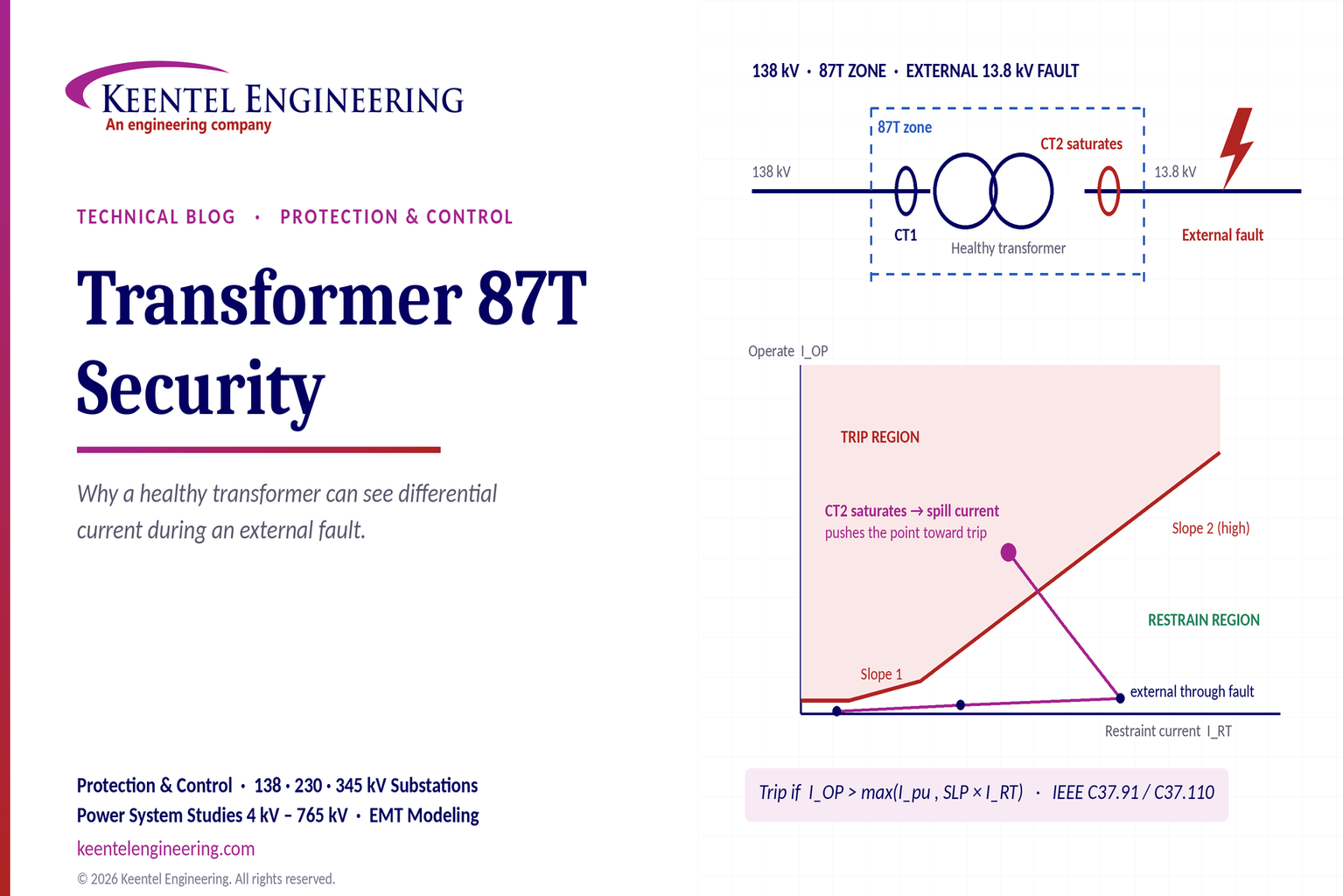
Learn why transformer differential relays detect current during external faults, how CT saturation causes spill current, and how secure 87T protection prevents trips.

By SANDIP R PATEL
•
October 3, 2026
Engineering guide to PRC-028 disturbance recording, PRC-029 ride-through and PRC-030 event detection for inverter-based resources.

By SANDIP R PATEL
•
October 3, 2026
A practical guide to SSO classification, SSR, PEDI, Wind-SSCI, EMT analysis, mitigation and protection based on CIGRE TB 909.

By SANDIP R PATEL
•
October 3, 2026
Learn ERCOT generator testing for PFR, MOD-025 and MOD-026/027, including staged tests, capability verification, dynamic models and field testing.

By SANDIP R PATEL
•
October 3, 2026
Learn how PV string I-V curve testing identifies hidden solar performance losses, including soiling, shading, mismatch, degradation, and wiring faults.

By SANDIP R PATEL
•
October 3, 2026
Learn how active harmonic filters work, how to size AHF systems, reduce VFD harmonics, calculate losses, and meet IEEE 519 TDD limits at the PCC.





