



A Coordinated Electric System Interconnection Review—the utility’s deep-dive on technical and cost impacts of your project.

Challenge: Frequent false tripping using conventional electromechanical relays
Solution: SEL-487E integration with multi-terminal differential protection and dynamic inrush restraint
Result: 90% reduction in false trips, saving over $250,000 in downtime

Category Metric
VPP capacity (Lunar Energy) 650 MW
Lunar funding raised US$232 million
Data center BESS example 31 MW / 62 MWh
ERCOT grid-scale batteries 15+ GW
LDES tenders (H1 2026) Up to 9.3 GW
Lithium-ion share of LDES by 2030 77%
FEOC initial threshold 55%
BESS tariff rate (2026) ~55%
Capacity gain from analytics 5–15%

What is T&D Co-Simulation?

Confusing Physical Connections with Logical Nodes in IEC 61850

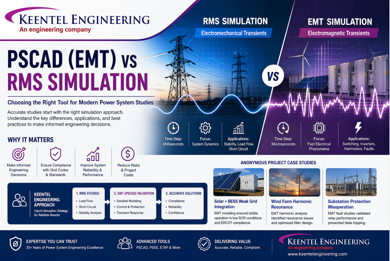
PSCAD (EMT) vs RMS Simulation: Choosing the Right Tool for Modern Power System Studies A Technical Guide by Keentel Engineering

PSCAD EMT vs RMS simulation infographic for power system stability, load flow, short circuit and harmonic analysis.
Calendar icon. D

 Apr 22, 2022  | blog

Introduction

The power system landscape is rapidly evolving. With the increasing penetration of renewable energy, inverter-based resources (IBRs), HVDC systems, and weak grid conditions, traditional simulation methods are no longer sufficient for accurate system analysis.


One of the most critical decisions engineers face today is:


  • Should I use RMS simulation or EMT simulation (PSCAD)?


Choosing the wrong approach can lead to:


  • Incorrect study results 
  • Protection system failures 
  • Grid instability 
  • Costly redesigns 


At Keentel Engineering, we specialize in helping utilities, developers, and EPCs select and implement the right simulation methodology, ensuring compliance, accuracy, and reliability.


1. Understanding Power System Simulation Types

Power system studies fall into two main categories:

1. Steady-State Analysis

  • No time dependency 
  • System evaluated at a single operating point 


Examples:


  • Load flow 
  • Short circuit (IEC 60909) 
  • Harmonics 
  • Protection coordination

2. Transient Analysis (Time-Based)

Transient analysis studies system behavior over time and is divided into:


Electromechanical Transients (RMS Simulation)


  • Time step: milliseconds 
  • Focus: generator dynamics and system stability 


Electromagnetic Transients (EMT Simulation – PSCAD)


  • Time step: microseconds 
  • Focus: fast electrical and switching phenomena 

2.1 RMS vs EMT: The Core Difference

Feature RMS Simulation EMT Simulation (PSCAD)
Time Resolution Milliseconds Microseconds
Model Detail Simplified Highly detailed
Waveform RMS/average Full waveform
Suitable For Stability studies Switching & inverter behavior
Tools PSSE, TSAT, ETAP PSCAD, EMTP, RTDS

3. Why EMT Simulation (PSCAD) is Critical Today

Modern grids include:


  • Solar PV 
  • Battery Energy Storage Systems (BESS) 
  • Wind farms 
  • Grid-forming inverters 


These systems operate using fast power electronics, which:


Cannot be accurately modeled using RMS tools


EMT Simulation Enables:


  • Sub-cycle transient analysis
  • Switching and lightning studies
  • Harmonic interaction
  • Converter control validation
  • Weak grid behavior analysis

4. Time Scale Matters

One of the most important distinctions:

Event Required Simulation
Generator stability RMS
Fault ride-through RMS + EMT
Lightning EMT
Switching transient EMT
Inverter control EMT

 5. The Biggest Mistake Engineers Make

 Using RMS tools for EMT problems


This leads to:


  • Misleading results 
  • Unstable designs 
  • Compliance failures 


Example:


RMS simulation:


  • Assumes averaged values 
  • Ignores switching 


EMT simulation:


  • Captures: 


  • DC offset 
  • waveform asymmetry 
  • switching behavior 

6. When to Use RMS vs EMT

Use RMS Simulation When:


  • Studying generator stability 
  • Performing load flow 
  • Conducting short circuit studies 
  • Evaluating steady-state behavior

Use EMT Simulation (PSCAD) When:

ANY of the following exist:


  • Inverter-based resources 
  • Weak grid (SCR < 3) 
  • HVDC systems 
  • Protection misoperation 
  • Harmonic resonance 
  • Fast switching events 

7. Keentel Engineering Approach

At Keentel Engineering, we follow a hybrid simulation strategy:

Step 1: RMS Studies


Step 2: EMT Validation (PSCAD)


  • Detailed inverter modeling 
  • Fault simulations 
  • Transient response validation 


Result:


  • Accurate system representation 
  • Utility compliance (ERCOT, PJM, WECC, CAISO) 
  • Reduced project risk 

8. Practical Engineering Insight

Fault Analysis Differences:

RMS:


  • Uses worst-case assumptions 
  • Provides conservative results 


EMT:


  • Models: 
  • Exact fault initiation 
  • waveform shape 
  • DC offset 


This is why EMT is required for:


  • Protection system validation 
  • Relay coordination in complex systems 

 9. PSCAD in Modern Grid Studies

PSCAD is widely used for:


  • Renewable interconnection studies 
  • BESS modeling 
  • HVDC analysis 
  • Grid-forming inverter validation 


Key Capabilities:


  • Detailed component modeling 
  • Control system integration 
  • High-resolution waveform analysis

10. Why Choose Keentel Engineering

With over 30 years of experience, Keentel Engineering offers:

EMT (PSCAD) Modeling


  • Solar, wind, BESS 
  • Grid-forming and grid-following inverters 


RMS + EMT Integration


  • PSSE + PSCAD workflows 
  • Model validation 


Compliance Support


  • NERC PRC standards 
  • IEEE 2800 
  • ISO grid requirements 


Protection & Control Studies


  • Relay validation 
  • Transient fault behavior

Technical FAQs (10 Detailed Questions & Answers)

  • 1. What is the main difference between RMS and EMT simulation?

    RMS simulation uses averaged values and larger time steps (milliseconds), while EMT simulation models detailed waveforms with microsecond resolution, capturing fast transients and switching effects.


  • 2. Why can’t RMS simulation model inverter behavior accurately?

    RMS models simplify inverter dynamics and ignore switching-level details, whereas EMT captures control algorithms and high-frequency switching behavior.


  • 3. What is a typical time step in EMT simulation?

    EMT simulations use time steps in the range of microseconds (1–50 µs), depending on system complexity and switching frequency.


  • 4. When is PSCAD mandatory for grid studies?

    PSCAD is required when dealing with:

    • Inverter-based resources 
    • Weak grids 
    • HVDC systems 
    • Fast transients 

  • 5. What is Short Circuit Ratio (SCR) and why does it matter?

    SCR indicates grid strength. Low SCR (<3) means a weak grid, requiring EMT studies for accurate stability analysis.


  • 6. Why do RMS short circuit results differ from actual fault currents?

    RMS studies use worst-case assumptions (e.g., bolted faults), while real faults include impedance and dynamic effects, resulting in lower actual currents.


  • 7. Can EMT and RMS simulations be used together?

    Yes, a hybrid approach is often used where RMS provides initial screening and EMT validates critical scenarios.


  • 8. What types of studies require EMT simulation?

    • Switching transients 
    • Harmonic resonance 
    • Inverter control validation 
    • Lightning analysis 

  • 9. How does EMT simulation help in protection studies?

    It captures waveform details such as DC offset and asymmetry, allowing accurate relay performance validation.

  • 10. What industries benefit most from EMT studies?

    • Renewable energy developers 
    • Utilities 
    • Transmission operators 
    • Industrial facilities 


Case Studies (Confidential Projects – Keentel Engineering)

Case Study 1: Solar + BESS Weak Grid Integration (ERCOT)

Scope:


  • 200 MW solar + 100 MW BESS 

Challenge:


  • Low SCR (~2.5) 
  • Voltage instability 

Solution:


  • Developed PSCAD EMT model 
  • Simulated inverter controls 

Result:


  • Stable operation achieved
  • NERC compliance approved
  • Reduced oscillations

Case Study 2: Wind Farm Harmonic Resonance (WECC)

Scope:


  • 300 MW wind project 


Challenge:


  • Harmonic resonance causing overheating 


Solution:


  • EMT harmonic analysis 
  • Filter design optimization 


Result:


  • Eliminated resonance
  • Improved reliability

Case Study 3: Substation Protection Misoperation (PJM)

Scope:


  • 500 kV substation 


Challenge:


  • Relay misoperation during faults 


Solution:


  • EMT fault simulation 
  • Relay model integration 


Result:


  • Corrected relay settings
  • Prevented false tripping

Conclusion

The choice between RMS and EMT simulation is not optional—it is critical.


  • RMS tools are ideal for system-level studies
  • EMT tools (PSCAD) are essential for modern grids


The future of power system studies lies in hybrid simulation approaches


Partner with Keentel Engineering

If your project involves:


  • Renewable integration 
  • Weak grids 
  • Complex transient behavior 


Keentel Engineering delivers accurate, compliant, and reliable solutions.


A smiling man with glasses and a beard wearing a blue blazer stands in front of server racks in a data center.

About the Author:

Sandip "Sonny" R. Patel, P.E.

IEEE Senior Member · Founder & CEO, Keentel Engineering

In 1995, Sonny Patel earned his Electrical Engineering degree from the University of Illinois. But degrees don't build legacies — action does.

For three decades, he has worked the power industry from every side of the table: 16 years as a utility engineer at Exelon/Commonwealth Edison; generation leadership across hydroelectric, industrial steam turbine, and a 9 GW renewable fleet; NERC Regional Entity Senior Compliance Engineer and Audit Team Lead, auditing some of the nation's largest utilities; and testing and commissioning lead on equipment up to 765 kV — the very top of the North American grid.

Utility. Generator. Regulator. Consultant. Few engineers have seen all four seats. Fewer still have sat in them.His experience spans nuclear, hydro, conventional generation, renewables, oil and gas, mining — and today's data centers, where he is authoring a three-book series on data center design. He is a Licensed Professional Engineer in six states and a Licensed Electrical Contractor in Florida (Unlimited EC) — he doesn't just design the work; he's qualified to stand behind its execution.Today, as Founder and CEO of Keentel Engineering, Sonny leads 51 engineers delivering substation design, power system studies, NERC compliance, and commissioning — done right, coast to coast.Three decades. Every side of the table. One standard: accountable engineering

Four workers in safety vests and helmets stand with arms crossed near wind turbines.

Let's Discuss Your Project

Let's book a call to discuss your electrical engineering project that we can help you with.

Man in a blazer and open shirt, looking at the camera, against a blurred background.

About the Author:

Sandip "Sonny" R. Patel, P.E.

IEEE Senior Member · Founder & CEO, Keentel Engineering

In 1995, Sonny Patel earned his Electrical Engineering degree from the University of Illinois. But degrees don't build legacies — action does.

For three decades, he has worked the power industry from every side of the table: 16 years as a utility engineer at Exelon/Commonwealth Edison; generation leadership across hydroelectric, industrial steam turbine, and a 9 GW renewable fleet; NERC Regional Entity Senior Compliance Engineer and Audit Team Lead, auditing some of the nation's largest utilities; and testing and commissioning lead on equipment up to 765 kV — the very top of the North American grid.Utility. Generator. Regulator. Consultant. Few engineers have seen all four seats. Fewer still have sat in them.His experience spans nuclear, hydro, conventional generation, renewables, oil and gas, mining — and today's data centers, where he is authoring a three-book series on data center design. He is a Licensed Professional Engineer in six states and a Licensed Electrical Contractor in Florida (Unlimited EC) — he doesn't just design the work; he's qualified to stand behind its execution.Today, as Founder and CEO of Keentel Engineering, Sonny leads 51 engineers delivering substation design, power system studies, NERC compliance, and commissioning — done right, coast to coast.Three decades. Every side of the table. One standard: accountable engineering

Leave a Comment

Related Posts

Station battery sizing design for substation DC auxiliary power system
By SANDIP R PATEL September 5, 2026
Understand ERCOT BESS interconnection requirements, including model packages, EMT studies, ride-through compliance, telemetry, and real-time co-optimization.
Transformer vector groups showing 30-degree HV and LV phase displacement at clock positions 11 and 1
By SANDIP R PATEL September 3, 2026
Learn transformer vector groups, clock notation, 30° phase shift, IEC vs ANSI conventions, grounding, differential protection and paralleling.
Station battery sizing design for substation DC auxiliary power system
By SANDIP R PATEL September 3, 2026
Learn how station battery sizing works, including duty cycles, ampere-hour calculations, voltage checks, chargers, DC systems, and substation reliability.
Transmission structure design showing angle classes and line support requirements.
By SANDIP R PATEL September 3, 2026
Learn how transmission structure design works, including structure types, loading cases, materials, foundations, right of way, and selection factors.
BESS energy capacity comparison showing installed, usable, guaranteed, POI and net delivered megawat
By SANDIP R PATEL September 3, 2026
Learn the difference between BESS nameplate, usable, guaranteed and delivered energy, including degradation, round-trip efficiency, auxiliary loads and testing.
ERCOT frequency response testing for generator compliance
By SANDIP R PATEL September 3, 2026
Understand ERCOT frequency response testing, from droop and deadband requirements to staged test procedures, data analysis, and compliance reporting.
STATCOM reactive power support improving voltage stability in modern power systems.
By SANDIP R PATEL September 3, 2026
Learn what a STATCOM does, how it supports voltage stability, reactive power control, weak grids, and why dynamic studies are essential for proper sizing.
Power system protection schemes from generator to load showing overlapping protection zones
By SANDIP R PATEL September 1, 2026
Learn power system protection schemes from generator to load, including protection zones, relay coordination, device numbers, backup protection, and settings.
PRC-029-1 compliance deadlines and enforcement discretion for inverter-based resources
By SANDIP R PATEL September 1, 2026
Understand PRC-029-1 compliance deadlines, IBR ride-through requirements, R1–R4, enforcement discretion, notification rules, and owner action steps.













