
A Coordinated Electric System Interconnection Review—the utility’s deep-dive on technical and cost impacts of your project.
Challenge: Frequent false tripping using conventional electromechanical relays
Solution: SEL-487E integration with multi-terminal differential protection and dynamic inrush restraint
Result: 90% reduction in false trips, saving over $250,000 in downtime
ERCOT enforces all of the above through simulation, which means your model is your compliance case. The bar is now high:
- Whole-facility scope. The model must represent everything the IT load, the UPS and power conversion, the cooling plant, the protection and control systems in formats compatible with ERCOT's study platforms (PSS/E, PSCAD, TSAT).
- Real control loops, not approximations. Generic textbook representations are unacceptable. The model must capture the actual inner control behavior of your power electronics.
- Hardware-validated converter models. For electronic loads, the PSCAD model must be benchmarked against actual hardware testing including voltage ride-through and subsynchronous response. A model assembled from standard PSCAD library blocks fails by definition, because a generic block has never been tested against your vendor's hardware. The good news: validation is a hardware-type test, so results for a given converter product are reusable across every facility that uses it.
- Format migration. Facilities that previously submitted the older composite load model (CMLD) format must transition to EPRI's PERC1 format.
- Three checkpoints. Models are reviewed before the stability study begins (no model, no study), before each quarterly stability assessment, and for electronic loads one final time before energization, when you must submit as-built models with a documented comparison against the previously studied data and a sworn attestation that the model matches actual field settings. ERCOT's review takes 10 business days, extendable by 20 put it on your critical path.
- A living obligation. Change your technology, controls, or relay settings in a way that affects ride-through including converting a crypto mining site to an AI data center — and you've triggered a new interconnection study, even if your megawatts don't change.
| Parameter | Detail |
|---|---|
| System | 230 kV / 138 kV transmission corridors, wind and wet-snow icing exposure |
| Data basis | 15 years of minute-resolution forced-outage records + regional weather observations |
| Core methods | Event grouping, MVA performance curves, time-to-95%-restore, area outage rate curves, fragility modeling, rerun-history benefits, exceedance and log-domain risk metrics |
| Headline result | ≈85% of maximum resilience benefit at 60% of original capital; worst-event restoration window cut from 11 days to 5 in rerun-history terms |
| Decision supported | Capital portfolio selection; resilience plan filing; post-investment verification framework |
| System / Topic | Governing Standard(s) | What It Controls |
|---|---|---|
| Overall plant electrical distribution | IEEE 141 (Red Book); IEEE 666 | Distribution architecture, voltage selection, design of generating station auxiliary service systems |
| Power system studies | IEEE 399 (Brown Book); IEEE 551 | Load flow, symmetrical/asymmetrical short circuit, motor starting methodologies down to the lowest LV panelboard |
| Protection & coordination | IEEE 242 (Buff Book); IEEE 3004.5; IEEE C37 series | Generator relaying (21, 59N, 87G), time-current coordination, selective clearing between LV and MV tiers |
| GSU / UAT / SST transformers | IEEE C57.12.00 and C57 family | Transformer ratings, impedance, testing, loading |
| HV switchyard breakers | IEEE C37.06 | AC high-voltage circuit breaker preferred ratings |
| MV switchgear (13.8 kV) | IEEE C37.20.2; IEEE C37.20.7 | Metal-clad construction, compartmentalization, vacuum breakers; arc-resistant design with plenum venting |
| MV cable | UL 1072; ICEA S-93-639 (NEMA WC 74) | Type MV-105 shielded cable, 133% insulation level for HRG systems |
| LV switchgear (480 V) | IEEE C37.13; UL 1558 | Metal-enclosed LV power circuit breaker switchgear to 635 V, draw-out ACBs with electronic trip units |
| Motor control centers | UL 845; NEMA ICS 18 | LV-MCC construction, MCCB/MCP protection for motors under ~200 HP |
| Motors | NEMA MG-1 | Motor performance, starting characteristics, service factors |
| DC & battery systems | IEEE 485; IEEE 946 | Lead-acid battery sizing (125/250 VDC), DC auxiliary system design |
| Grounding | IEEE 80; IEEE 142 (Green Book) | Ground grid step/touch potential limits; system grounding including high-resistance grounding |
| Lightning protection | IEEE 998 | Direct-stroke shielding of switchyard and outdoor generator structures |
| Arc flash & electrical safety | IEEE 1584; NFPA 70E | Incident energy calculation; worker safety boundaries and PPE |
| Fire protection | NFPA 850 | Fire protection and risk management for combustion turbine generating plants |
| Installation code | NEC (NFPA 70); NESC | Wiring methods inside the plant fence; overhead/outdoor clearances at the switchyard |
| Interconnection & compliance | FERC LGIP; NERC MOD-025/026/027, PRC-019/024/029, FAC-008 | Interconnection process, model validation, protection/ride-through coordination, facility ratings |
| IFC / Construction Deliverable | Purpose |
|---|---|
| Stamped IFC packages | Legal basis for construction; P.E. responsible charge |
| Final relay settings & TCCs | Protection as-installed matches the coordination study |
| Calculation archive | Owner records; NERC audit evidence trail |
| Commissioning procedures | Safe, sequenced energization; MOD field testing |
| Construction support | RFIs, field changes, FAT/SAT witness |
| As-builts & model handoff | Operating baseline; future study currency |
| Metric | Outcome |
|---|---|
| Defects found pre-occupancy | Three topology defects and one settings-mismatch family corrected before load migration; the shared-switchboard defect alone would have invalidated the concurrently-maintainable claim on day one |
| IST findings | Fourteen additional discrepancies surfaced under scenario testing (control logic, alarm mapping, one generator sequencing fault) — all closed before handover instead of during operations |
| Black-building test | Passed on second execution; the first attempt exposed the generator sequencing fault under true block load, exactly the failure the compressed plan would never have found |
| Handover quality | Operations team certified on the actual failure scenarios; corrected EOPs and settings documentation delivered as controlled documents |
| Business outcome | Occupancy proceeded three weeks behind the original date — against an independent estimate that the uncorrected sequencing fault carried a high probability of a full facility outage within the first year |
Part 2 — Frequently Asked Questions: Large Load Interconnection
An electric grid must remain in continuous balance — generation onto the grid must equal consumption from it at every instant. PJM achieves this balance, and prices it, through a layered market architecture. Each layer operates on a different time horizon, and each one touches project economics differently.
| Domain | Key Standards / Codes | What They Govern |
|---|---|---|
| Fire safety | NFPA 855; UL 9540 / UL 9540A | Installation requirements, separation, gas management; system safety listing and thermal-runaway fire testing |
| Grid interconnection | IEEE 1547 (distribution); IEEE 2800 (transmission IBRs) | Ride-through, reactive capability, power quality, and performance at the point of interconnection |
| Power quality | IEEE 519 | Harmonic distortion limits at the PCC |
| Protection & grounding | IEEE 80 / 81 / 142; C37 series | Grounding system design and testing; protective relaying |
| Reliability compliance | NERC standards (incl. PRC ride-through requirements) | Registered-entity obligations for grid-connected storage |
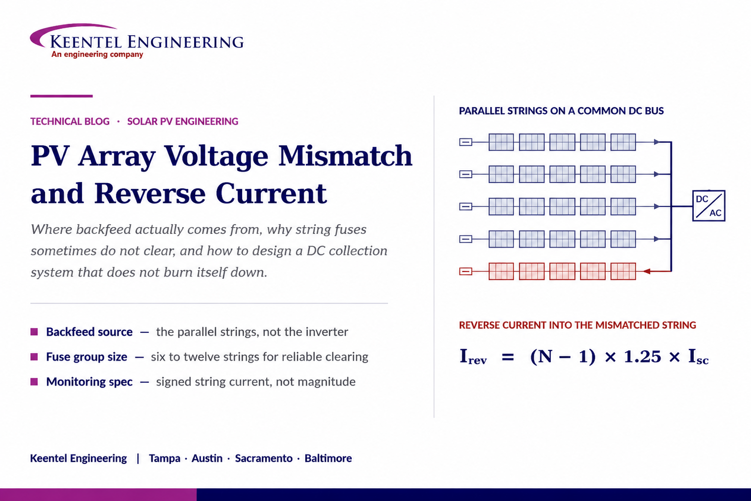
PV Array Voltage Mismatch and Reverse Current
Aug 27, 2026 | Blog
Where Backfeed Actually Comes From, Why String Fuses Sometimes Do Not Clear, and How to Design, Commission, and Monitor a DC Collection System That Does Not Burn Itself Down
1. Executive Summary
Every utility-scale and commercial PV array is a collection of independent current sources forced to share a single voltage. That one architectural fact — parallel strings tied to a common DC bus and operated at a single maximum power point — is the origin of nearly every DC-side reliability problem the industry deals with: mismatch loss, hot spots, combiner fires, welded connectors, blown string fuses that do not clear, and inverter-level harvest deficits that show up in production reports as an unexplained one to four percent.
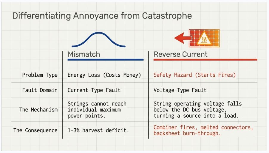
Mismatch and reverse current are frequently discussed as if they were the same phenomenon. They are not. Mismatch is an energy problem: strings that cannot reach their individual maximum power points give up yield. Reverse current is a safety problem: a string whose operating voltage falls below the DC bus voltage stops being a source and becomes a load, and the healthy strings in parallel with it push current backwards through it. The first costs money. The second starts fires.
The transition between the two is not gradual and it is not symmetric. Light soiling and partial shading almost never produce destructive reverse current — they reduce current, not voltage, and the string simply operates off-peak. What produces destructive reverse current is anything that collapses string voltage: a string built with fewer modules than its neighbors, a module with multiple bypass diodes conducting or shorted, a cracked-cell cluster that opens a substring, a ground fault on a floating array, or the single most damaging commissioning error in the industry — a string landed with reversed polarity.
This paper works through the physics, the arithmetic, the code and standards framework, and the practical design decisions: how to size a string fuse inside a constraint window that modern high-current modules have made uncomfortably narrow, when a fuse will and will not clear, when fuseless architecture is legitimate, and what instrumentation actually detects the failure before it becomes a claim. It closes with a commissioning protocol, an O&M trending regime, and a twenty-question FAQ.
The single most important idea in this paper
A string fuse in a PV array is back-fed. Its available fault current does not come from a utility source with thousands of amps behind it — it comes from the handful of other strings on the same combiner bus, and it is limited to roughly 1.25 times short-circuit current per contributing string.
If there are not enough parallel strings, the available backfeed current can land in the fuse's non-clearing region: high enough to run the element hot indefinitely, not high enough to open it. That is a combiner fire waiting for a hot afternoon, and it is a design decision, not a maintenance failure.
2. Why Parallel Strings Share a Voltage
A photovoltaic module is a current source with a voltage ceiling. Short-circuit current scales almost linearly with irradiance and drifts only slightly with temperature. Open-circuit voltage is nearly independent of irradiance above a few hundred watts per square metre and falls with cell temperature at roughly 0.24 to 0.30 percent per degree Celsius depending on cell technology. Series-connecting modules into a string adds voltage; paralleling strings adds current.
When strings are paralleled on a combiner bus, they no longer have individual operating points. Kirchhoff makes the bus voltage common to all of them. The inverter's maximum power point tracker sweeps that single bus voltage looking for the peak of the aggregate power curve, and it finds a compromise: a voltage that is optimal for the population average and suboptimal for every individual string that deviates from it.
For a healthy array this is a small, well-behaved loss. Modules are binned, strings are the same length, and the spread in string maximum power voltage is a percent or two. The MPPT settles near the middle of the distribution and each string operates within a few tenths of a percent of its own peak. Standard energy models capture this as a module and string mismatch loss of roughly one to three percent, and it is the least interesting number in the loss table.
The behaviour changes character when a string deviates far enough that the common bus voltage lies outside its useful operating range. A string whose open-circuit voltage is below the bus voltage has no operating point on its own I-V curve at that voltage. It is driven into the fourth quadrant — positive current in the reverse direction, or equivalently negative power — and it dissipates energy instead of producing it.
2.1 The Fourth-Quadrant Condition Stated Precisely
Reverse current flows in a string when the DC bus voltage exceeds the string's open-circuit voltage at the prevailing cell temperature and irradiance. That is the condition. Everything else — shading, cracking, diode failure, wrong module count — matters only insofar as it drives a string toward that inequality.
This is why the distinction between current-limiting faults and voltage-collapsing faults is the central diagnostic question on the DC side. Soiling reduces Isc; the string still develops nearly full Voc and stays a source. A shorted bypass diode removes the voltage of one substring; on a twenty-eight-module string that is a two to four percent voltage deficit — a yield problem, not a reversal. But a string wired with twenty-four modules where its neighbours have twenty-eight is fourteen percent short, and at high cell temperature on a clear day that string can sit below bus voltage for most of the production window, every day, for years.
Diagnostic shorthand
Current-type faults (soiling, uniform shading, glass haze, encapsulant browning): string current falls, string voltage nearly intact, no reversal, energy loss only.
Voltage-type faults (missing modules, conducting or shorted bypass diodes, open substrings from cracked cells, ground faults, reversed polarity): string voltage collapses, reversal becomes possible, thermal and fire risk enters the picture.
The remote monitoring alarm that matters is not "low string current" — it is "string current sign reversal" and "string voltage deviation from combiner median."
3. Taxonomy of Mismatch
Mismatch sources should be classified by whether they are designed in, built in, or developed over life, because the mitigation differs completely across those three categories.
3.1 Design-Origin Mismatch
- Unequal string lengths. Terrain breaks, setback constraints, and racking table geometry tempt designers into partial strings. A short string on a shared MPPT is a permanent voltage deficit and a permanent reverse-current candidate.
- Mixed module models, bins, or vintages on a shared MPPT. Repowering and warranty replacement are the usual culprits. Two modules from different production years can differ by several percent in Vmp.
- Mixed orientation or tilt on a shared MPPT. East and west sub-arrays have different irradiance profiles and different cell temperatures, therefore different Vmp trajectories through the day.
- Bifacial rear-irradiance non-uniformity. Edge rows, rows over disturbed or vegetated ground, rows adjacent to access roads, and rows near equipment pads see materially different rear-side gain. Mixing edge-row and interior-row strings on one MPPT builds mismatch into the plant.
- Excessive strings per fuse group, or too few. Both directions create problems — the first exceeds module reverse-current withstand, the second leaves the fuse unable to clear.
3.2 Construction-Origin Mismatch
- Reversed polarity strings. A string landed backwards presents a negative voltage to a positive bus. The reverse current is immediate and severe, limited only by the parallel strings and the string's own series resistance.
- Cross-mated connectors. Mating a connector from one manufacturer to a visually similar connector from another produces a joint with poor contact pressure and a high-resistance interface that degrades under thermal cycling. This remains one of the leading root causes of DC-side fires.
- Under-torqued or over-torqued terminations at fuse holders, bus bars, and lugs.
- Modules damaged in handling — walked on, dropped on a corner, or torqued during racking — producing cracks that are electrically invisible at commissioning and open circuits after two winters of thermal cycling.
- Missing or backwards module-level jumper in a string, producing a string one module short that nobody counts.
3.3 Life-Origin Mismatch
- Cell cracking propagation. Microcracks from transport and installation grow under thermal and mechanical cycling until they isolate cell regions, forcing bypass diodes into conduction.
- Bypass diode failure. Diodes fail short (removing substring voltage permanently and quietly) or open (removing hot-spot protection and setting up a far worse failure).
- Potential-induced degradation. PID reduces shunt resistance, hitting fill factor first and voltage at low irradiance, and it is spatially non-uniform — worst at the string ends with the highest potential to ground.
- Non-uniform soiling and vegetation encroachment. A row shaded at its base by unmanaged vegetation drives bypass diodes into conduction for hours a day.
- Junction box and connector resistance growth from moisture ingress and thermal cycling.
- Ground faults developing in cable insulation abraded at racking edges or damaged by rodents and mowing equipment.
4. Quantifying Reverse Current
The magnitude of reverse current into a compromised string is bounded by what the parallel strings can supply. In a combiner with N parallel strings, if one string is fully compromised, the remaining N minus one strings can each deliver up to their short-circuit current into it. Applying the standard 125 percent irradiance-enhancement factor that accounts for cloud-edge focusing and above-STC irradiance events:
Ireverse, max = (N − 1) × 1.25 × ISC
This is the number that must be compared against the module's reverse-current withstand. It is also, and this is the point routinely missed, the available fault current for the string fuse. There is no other source. A grid-tied transformerless inverter does not sustain reverse current into the array; its DC-link capacitance contributes a brief transient at most and its bleed circuits discharge the bus when it is not operating.
4.1 Worked Example
Take a modern n-type bifacial module: 585 W, Isc of 13.9 A at STC front-side, maximum series fuse rating of 25 A on the nameplate. Consider three combiner configurations.
| Strings per combiner (N) | Available reverse current into one faulted string | Ratio to a 25 A string fuse | Practical consequence |
|---|---|---|---|
| 2 | 17.4 A | 0.70× | Fuse will never operate. Reverse current is below module withstand, so protection is arguably unnecessary — but the fuse provides no protection either. |
| 4 | 52.1 A | 2.08× | Marginal. Clearing time is long and strongly irradiance-dependent; at 400 W/m² the ratio drops below 1 and the fuse sits hot without clearing. |
| 8 | 121.6 A | 4.86× | Reliable clearing at moderate to high irradiance. This is where a fused combiner design should live. |
| 16 | 260.6 A | 10.4× | Fast clearing, but reverse current far exceeds the 25 A module withstand, so the fuse must clear before the module is damaged — fuse I²t coordination becomes the governing check. |
The table shows the real design tension. Too few strings and the fuse cannot clear. Too many and the module is exposed to reverse current an order of magnitude above its rating during the fuse's clearing time. The workable band for a fused combiner with contemporary high-current modules is typically six to twelve strings per protected group, and it should be verified arithmetically for the specific module and fuse, not assumed from a standard combiner catalogue.
4.2 The Irradiance Problem
Fault current in a PV array scales with irradiance. A fault that occurs at 1000 W/m² may clear in under a second. The same fault at 300 W/m² presents roughly thirty percent of the current, which for most PV fuse time-current curves is deep in the non-clearing region. The fuse element runs at elevated temperature, the fuse holder's spring contacts anneal, contact resistance rises, and the assembly enters a thermal runaway that ends in an arcing fault inside a sealed polymer enclosure.
This is the mechanism behind a meaningful share of combiner box fires, and it is why a design review that stops at "the fuse rating is below the module maximum series fuse rating" has not actually reviewed the protection.
5. Module Withstand and the Maximum Series Fuse Rating
Every module nameplate carries a maximum series fuse rating, sometimes labelled maximum overcurrent protective device rating. It is not an arbitrary number and it is not the same as the module's current rating. It is derived from the module's demonstrated ability to survive reverse current without ignition, established by the reverse-current overload test in the module safety standard — MST 26 in IEC 61730-2, carried through into the harmonised UL 61730 series that replaced UL 1703 in North America.
In that test the module is subjected to a reverse current of 1.35 times the declared maximum overcurrent rating for a defined duration while wrapped in tissue paper, and the acceptance criterion is that nothing ignites. It is a fire-safety qualification, not a performance rating. Passing it does not mean the module is undamaged; a module that has taken sustained reverse current should be treated as compromised and replaced regardless of whether it still produces power.
Two ratings, two different jobs
Maximum series fuse rating (typically 15 A to 30 A): the largest overcurrent device allowed upstream of the module. It caps fuse selection from above.
Short-circuit current Isc (typically 11 A to 19 A for current-generation large-format modules): drives the minimum fuse rating from below via the code multiplier.
As Isc has climbed with larger wafer formats while maximum series fuse ratings have not climbed proportionally, the gap between the floor and the ceiling has narrowed. On some modules the usable fuse window is now a single standard rating.
6. Fuse Selection: A Four-Sided Constraint Window
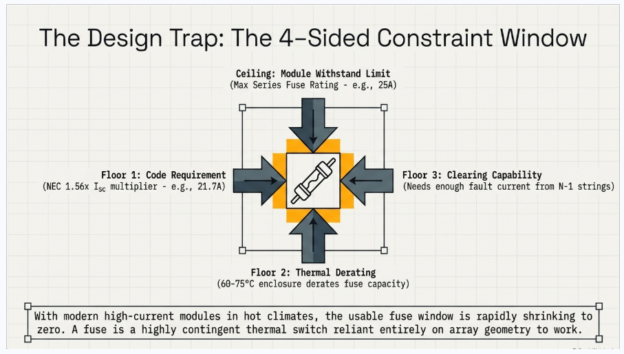
String fuse selection is over-constrained. Four independent requirements must be satisfied simultaneously, and on high-current modules in hot climates they are not always all satisfiable — which is itself a design finding that should be reported rather than papered over.
6.1 Constraint One — Do Not Nuisance-Operate
The National Electrical Code establishes maximum PV source circuit current as 125 percent of module short-circuit current, and then requires the overcurrent device to be rated at not less than 125 percent of that value. The compound result is the familiar 156 percent multiplier. A 13.9 A module therefore requires a fuse of at least 21.7 A, rounding up to the next standard size.
6.2 Constraint Two — Do Not Exceed Module Withstand
The fuse rating must not exceed the nameplate maximum series fuse rating. With a 25 A nameplate and a 21.7 A floor, the entire selectable window for the example module is a 25 A fuse. There is no engineering margin left in either direction.
6.3 Constraint Three — Derate for Enclosure Temperature
PV fuses are qualified at a reference ambient, but combiner enclosures in desert and high-plains sites routinely reach 60 to 75 degrees Celsius internally under full sun with the array producing. Manufacturers publish derating curves; a common figure is 70 to 80 percent of nominal rating at 60 degrees Celsius and lower still above that. A 25 A fuse in a 70 degree enclosure may only be good for 18 to 20 A continuous — below the 21.7 A the code requires.
That contradiction cannot be resolved by ignoring it. The available responses are a larger fuse (blocked by the module rating), a cooler enclosure (ventilated or shaded combiners, light-coloured enclosures, thermal modelling of the installed condition), a different fuse series with a better temperature characteristic, fewer strings per combiner to reduce internal heat load, or a fuseless architecture. Choosing among those is a real engineering decision with cost and reliability consequences on both sides.
6.4 Constraint Four — Be Able to Clear
The available backfeed current from Section 4 must be high enough, at the irradiance levels where faults actually occur, to drive the fuse into its clearing region within a time short enough to protect the compromised string. Working backwards from a target of roughly three times nominal fuse current for reliable operation and the 156 percent floor, the minimum string count per protected group falls in the range of five to six. Below that, a fuse is decoration.
| Constraint | Governing requirement | Direction of pressure | Typical failure if ignored |
|---|---|---|---|
| Nuisance operation | NEC 690.8(A) and 690.9(B): 1.56 × Isc floor | Pushes fuse rating up | Fuses open on clear high-irradiance days; string outages attributed to "bad fuses" |
| Module withstand | Nameplate maximum series fuse rating; IEC 61730-2 MST 26 basis | Caps fuse rating | Module reverse-current damage, hot spots, backsheet burn-through |
| Thermal derating | Fuse manufacturer derating curve at installed enclosure temperature | Pushes required rating up | Chronic hot fuse holders, contact annealing, combiner arcing faults |
| Clearing capability | Available backfeed = (N−1) × 1.25 × Isc versus fuse time-current curve | Sets minimum string count | Non-clearing faults, sustained heating, fire |
7. Fused and Fuseless Architecture
Both the North American and IEC frameworks recognise that string overcurrent protection is not always required. The logic is identical in both: if the worst-case reverse current the parallel strings can deliver is below what the module can withstand, there is nothing for a fuse to protect against.
The IEC array design standard expresses this as a direct comparison — protection may be omitted where the number of parallel strings minus one, multiplied by module short-circuit current, does not exceed the module's maximum overcurrent rating. The NEC reaches the same place through the overcurrent protection article, where the requirement attaches to circuits that could be subject to currents exceeding conductor ampacity from parallel sources, with the familiar allowance for arrangements with a small number of source circuits and no external sources.
In practice, with modules in the 13 to 19 A Isc range and 20 to 30 A maximum series fuse ratings, genuine fuseless operation is limited to two, occasionally three, parallel strings per protected group. That is a common architecture in residential and small commercial work and in string-inverter plants where each MPPT input takes two strings directly. It is not a utility-scale central-inverter combiner architecture.
7.1 The Awkward Middle
Between roughly three and five strings per group, neither architecture is comfortable. Reverse current exceeds module withstand, so fuseless is not defensible; but available backfeed current is too low for confident fuse clearing. Designs that land here should be restructured — either consolidate to a higher string count per fuse group or split to a genuinely fuseless two-string arrangement — rather than accepting a protection scheme that only works on paper.
7.2 One Pole or Two
Whether to fuse both polarities depends on the array's earthing architecture. In a functionally grounded system where the reference is established through the inverter, a single fuse per string in one polarity is the common approach. In a genuinely floating array, a single ground fault does not by itself produce current, but a second fault in the opposite polarity elsewhere in the array creates a loop that a single-pole fuse arrangement may not interrupt at both ends. The decision should follow from the inverter's earthing topology, the ground-fault detection scheme, and the applicable code edition, and it should be documented in the design basis rather than inherited from a combiner vendor's standard product.
8. Code and Standards Framework
The following are the provisions that a DC collection design review should actually be able to cite. Editions differ by jurisdiction and by the code cycle adopted locally; the design basis should name the specific edition in force.
| Reference | Subject | Relevance to mismatch and reverse current |
|---|---|---|
| NEC Article 690.8 | Circuit sizing and current | Establishes maximum PV source circuit current at 125% of Isc, and conductor ampacity at 125% of that value |
| NEC Article 690.9 | Overcurrent protection | Requires string overcurrent protection where parallel sources can exceed conductor ampacity; sets device rating basis and the conditions under which protection may be omitted |
| NEC Article 690.11 | DC arc-fault protection | Arc-fault detection requirement for PV DC circuits above the voltage threshold on or penetrating buildings; frequently specified by owners beyond code minimum on ground-mount plants |
| NEC Article 690.13 / 690.15 | Disconnecting means | Isolation provisions that determine how a compromised string can be safely removed from the bus |
| UL 61730-1 / -2 | PV module safety | Harmonised module safety standard; contains the reverse-current overload qualification underlying the maximum series fuse rating |
| IEC 61730-2, MST 26 | Reverse current overload test | The test that establishes module reverse-current withstand at 1.35 × declared maximum overcurrent rating |
| IEC 61215, MQT 09 | Hot-spot endurance | Qualifies module behaviour under localised reverse bias and cell shading |
| UL 248-19 / IEC 60269-6 | Photovoltaic fuses | Fuse construction, DC interruption, and time-current characteristics specific to PV service |
| IEC 62548 | PV array design requirements | String protection criteria, the fuseless allowance, and the string fuse sizing window |
| IEC 62446-1 | Commissioning and verification | Category 1 and Category 2 test regimes including I-V curve verification and insulation resistance |
| IEC TS 62446-3 | Outdoor infrared thermography | Method, conditions, and reporting for IR inspection of PV modules and arrays |
| IEC TS 60904-13 | Electroluminescence imaging | Method for crack, inactive-area, and interconnect defect detection |
| NFPA 70E | Electrical safety in the workplace | DC arc-flash assessment; note that IEEE 1584 covers AC only, so DC incident energy uses the maximum power or Doan approaches |
9. What Actually Fails, and How
9.1 Cell-Level Hot Spots
When reverse current is forced through a string, it must pass through every cell in series. A cell that is cracked, shaded, or mismatched relative to its neighbours cannot carry that current at forward bias, so it goes into reverse bias. The reverse-bias voltage across that one cell can reach tens of volts before breakdown, and the product of that voltage and the string current is dissipated in a few square centimetres of silicon.
Localised temperatures well above 150 degrees Celsius are readily reached. The consequences progress from encapsulant browning and delamination, through solder joint reflow and interconnect ribbon failure, to backsheet scorching and, in the worst case, ignition. Bypass diodes are the designed defence — they clamp substring reverse voltage to roughly a volt — but a diode that has failed open removes that defence entirely, and a diode that has failed short removes substring voltage and pushes the string closer to the reversal condition in the first place.
9.2 Bypass Diode Thermal Failure
A conducting bypass diode carries full string current, and in a reverse-current event it carries the backfeed current from all parallel strings. Junction box thermal design assumes intermittent conduction under transient shading, not sustained conduction under a permanent voltage-collapse fault. Sustained conduction drives junction temperature up, forward voltage down, and current concentration higher, which is a positive-feedback path to junction failure. Once the diode fails open, the substring it was protecting is exposed.
9.3 Connector and Termination Failure
Reverse current does not stop at the module. It flows through every connector, splice, fuse holder, and lug in the string path. A joint with elevated contact resistance dissipates I-squared-R at a point with almost no thermal mass. Cross-mated connectors, connectors field-crimped without the manufacturer's tooling, and connectors mated with contamination on the pins are the usual sites. The failure signature — a melted connector shell with copper conductor visible and the racking scorched beneath — is one of the most common DC-side incident photographs in the industry.
9.4 DC Arcing
Direct current does not have a natural zero crossing. An arc established in a DC circuit at 1000 or 1500 V sustains itself as long as the source can supply current and the gap geometry permits. Series arcs (a degraded connection in the string path) and parallel arcs (insulation breakdown between conductors or to ground) both become plausible once thermal degradation has begun. Arc-fault detection is the mitigating control, but it is a detection layer over a design problem, not a substitute for correct protection sizing.
9.5 Harvest Loss and Inverter Behaviour
The energy consequence is often larger than operators assume, because it is not confined to the affected string. When a badly mismatched string is present on an MPPT, the tracker's aggregate power curve develops local maxima. A tracker that settles on a local rather than global maximum can leave several percent of the MPPT's output on the table across every string it serves, not just the compromised one. Global scan intervals, sweep behaviour, and the inverter's handling of multi-peak curves become material — and vary considerably between manufacturers and firmware versions.
10. Reading the Standard Diagram Correctly
The one-line and block-diagram treatments of this topic that circulate widely — including the array diagram that prompted this paper — communicate the shape of the problem well and get several important details wrong. Four clarifications are worth making explicitly, because the errors have design consequences.
Clarification 1 — The inverter is not the source of reverse current
Diagrams commonly draw an arrow from the inverter back into the array, labelled reverse flow. In a grid-tied transformerless PV inverter this is not the sustained mechanism. The inverter presents a controlled DC bus voltage; it does not push power back into the array. The source of sustained reverse current is the healthy parallel strings on the same bus, and the correct arrow runs laterally from string to string through the combiner bus, not backwards from the inverter. This matters because it determines where the protection goes and what the available fault current is.
Clarification 2 — Mismatch and reverse current are different regimes
Showing soiled or lightly shaded modules and destructive backfeed in the same picture implies a continuum that does not exist. Reverse current requires the string voltage to fall below the bus voltage. Most soiling and most partial shading do not achieve that; they cost energy and nothing else. Treating every mismatch alarm as a fire risk produces alarm fatigue, and alarm fatigue is why the one that mattered got closed without a truck roll.
Clarification 3 — A fuse symbol is not protection
Every string in every diagram has a fuse symbol on it, which implies the problem is solved. As Section 6 shows, whether that fuse can clear depends on the number of parallel strings, the prevailing irradiance, and the enclosure temperature. The symbol carries none of that. A protection review must show the arithmetic.
Clarification 4 — Measurement belongs at the combiner, and it must be signed
Reverse-current measurement drawn at the end of a string is conceptually right but operationally impractical. The instrumentation that exists in real plants is at the combiner: a current transducer per string on the positive or negative leg. What determines whether it is useful is whether it reports signed current. A sensor that reports magnitude only cannot distinguish a string producing 8 A from a string absorbing 8 A, and the second condition is the one that burns.
Specification language that changes outcomes
Require string-level current monitoring with signed output and explicit negative-current alarming, not magnitude-only measurement.
Require accuracy sufficient to resolve a 5 percent deviation from combiner median at irradiance above 600 W/m², which in practice means better than ±1 percent of full scale.
Require combiner internal temperature monitoring with alarming, so that fuse-holder heating is visible before it becomes an incident.
11. Detection and Measurement
11.1 String Current Trending
The workhorse method. Compare each string's current to the median of its combiner group, filtered to irradiance above roughly 600 W/m² and to periods without transient shading. A persistent deviation beyond five percent over multiple days is a work order. A negative reading at any irradiance is an immediate dispatch. The filtering matters — unfiltered comparison at low irradiance generates enough false positives to make the alarm useless.
11.2 String Voltage and Open-Circuit Verification
Because reversal is a voltage phenomenon, string voltage is the more direct indicator, but it is rarely instrumented per string. Where it is not, periodic manual open-circuit voltage measurement per string, temperature-corrected using the module's temperature coefficient and compared to the combiner group, remains the fastest field screen for a voltage-type fault.
11.3 I-V Curve Tracing
The definitive diagnostic. A traced curve translated to standard test conditions and compared against the module datasheet distinguishes among fault classes by curve shape:
- Reduced Isc with normal Voc and fill factor: uniform soiling or irradiance-type loss.
- Reduced Voc with normal Isc: modules missing from the string, or shorted bypass diodes.
- A distinct step or shoulder in the curve: one or more bypass diodes in conduction, indicating shading or an open substring.
- Reduced fill factor with a shallow slope near Voc: series resistance growth — connectors, solder bonds, terminations.
- Reduced fill factor with a steep slope near Isc: shunt resistance loss, characteristic of PID or cell damage.
Full-population curve tracing at commissioning is the highest-value quality step available on the DC side, and it is the one most often cut for schedule.
11.4 Infrared Thermography
Aerial infrared survey has made full-plant thermal inspection economical. Interpretation follows recognisable patterns: a single hot cell indicates a cell-level defect under reverse bias; a hot substring band indicates a conducting bypass diode; a uniformly hot module indicates the module is short-circuited or carrying reverse current; a hot junction box indicates a diode or termination problem. Temperature differentials above roughly 20 kelvin against neighbouring cells warrant intervention. Surveys should be flown at irradiance above 600 W/m², with the plant producing, and reported per the applicable thermography technical specification.
11.5 Electroluminescence Imaging
For root-cause work on modules already flagged, electroluminescence reveals cracks, inactive cell regions, and interconnect failures that are invisible in both visual and thermal inspection. It is a night-time or enclosure method and is used on samples, not populations.
11.6 Insulation Resistance and Ground-Fault Detection
Ground faults on a floating array are a voltage-collapse mechanism and a reverse-current path. Insulation resistance testing per the commissioning standard, plus a functioning ground-fault detection and interruption or residual-current monitoring scheme at the inverter, closes the loop. Ground-fault detectors that have been bypassed to keep a plant online — which happens more than the industry likes to acknowledge — remove the only automatic defence against this class of fault.
12. Design Controls
The following controls, applied at design stage, eliminate most of the failure modes above at negligible cost. Applied after commissioning, the same items cost ten to a hundred times more.
- Build every string on a shared MPPT to identical module count. Where terrain forces a short string, give it a dedicated MPPT input or dedicated inverter, or omit it.
- Bin modules and keep a single bin within a combiner group. Record the binning in the as-built so that future replacements can respect it.
- Never mix module models or production vintages on a shared MPPT, including during warranty replacement. Maintain an attic stock of the original model for the life of the plant, or plan replacements at whole-MPPT granularity.
- Separate orientations and tilts onto separate MPPTs.
- For bifacial plants, group edge rows separately from interior rows where the layout permits, and specify uniform ground treatment beneath the array.
- Compute the four-sided fuse constraint window explicitly for the specific module and fuse series, at the actual expected combiner internal temperature, and document it. If the window is empty, change the architecture.
- Set strings per protected group to satisfy both the module withstand limit and the fuse clearing requirement — typically six to twelve for current module technology.
- Specify combiner enclosures with thermal performance appropriate to the site, not the catalogue default: ventilation or thermal management, light exterior finish, and where practical shading from the array itself.
- Specify signed string-level current monitoring with negative-current alarming and combiner internal temperature monitoring.
- Specify a single connector manufacturer and part number across the entire DC system, prohibit cross-mating in the specification, and require manufacturer tooling and installer certification for any field terminations.
- Specify arc-fault detection where it is code-required and evaluate it where it is not, particularly on plants with long service lives and limited site attendance.
- Perform DC arc-flash analysis for combiner and inverter DC compartment work, recognising that the AC incident-energy standard does not apply.
13. Commissioning Protocol
The commissioning sequence below is ordered so that the destructive errors are caught before the array is energised onto a common bus.
- Verify polarity on every string at the combiner before landing conductors on the bus. This is non-negotiable and it is the single highest-value step in the sequence.
- Measure open-circuit voltage on every string with the combiner bus open. Temperature-correct and confirm each string is within roughly two percent of the group mean. Any outlier is a module count or connection error and must be resolved before proceeding.
- Measure short-circuit or operating current on every string and confirm consistency within the group.
- Perform insulation resistance testing per the commissioning standard on every source circuit.
- Trace I-V curves on the string population — full population where the contract permits, otherwise a statistically defensible sample with mandatory full-population tracing on any combiner showing an outlier.
- Verify fuse ratings installed against the design calculation, physically, per combiner. Substitutions made in the field to keep a schedule are common and are exactly the failure this step exists to catch.
- Verify termination torque on every fuse holder, lug, and bus connection, and record it.
- Confirm the monitoring system reports signed string current and that negative-current alarms are configured and tested by injection or simulation.
- Perform a baseline aerial infrared survey with the plant producing at above 600 W/m², and archive it as the reference against which all future surveys are compared.
- Archive the commissioning dataset — string Voc, string current, I-V curves, insulation resistance, torque records, IR imagery — as the plant's electrical birth certificate. Its absence is the most common obstacle to a successful serial-defect warranty claim.
14. Operations, Trending, and Warranty
The operational regime that keeps this class of failure out of the incident log is unglamorous and consists of four habits.
First, trend string current against combiner median continuously, with irradiance filtering, and treat sign reversal as a dispatch condition rather than an alarm to be acknowledged. Second, repeat the aerial infrared survey annually and compare against the commissioning baseline rather than against an absolute threshold — the rate of appearance of new thermal anomalies is far more informative than the count. Third, sample I-V curves annually on a rotating basis so that the whole plant is traced over a three to five year cycle, which surfaces gradual degradation before it becomes mismatch. Fourth, treat any module that has carried reverse current as scrap, not as a candidate for return to service.
On the commercial side, this data has a second life. Serial defect claims against module and connector manufacturers succeed or fail on the quality of the baseline and the trend record. An owner who can demonstrate a defect population with commissioning I-V curves, sequential thermal surveys, and electroluminescence on failed samples is in a materially different negotiating position from an owner presenting photographs of burnt connectors.
15. How Keentel Supports This Work
Keentel Engineering provides the electrical design and engineering analysis behind DC collection systems that behave predictably over a twenty-five to thirty-five year service life. On PV and PV-plus-storage projects our involvement typically covers:
- DC collection system design and review — string sizing, combiner architecture, conductor sizing, and the explicit fuse constraint analysis described in Section 6, documented to a defensible design basis.
- Protection coordination across the DC collection system, inverter, and MV collection, including DC arc-flash analysis for maintenance work planning.
- Owner's engineer services — specification development, design review of EPC submittals, factory and site witness testing, and commissioning oversight including I-V curve and thermography programme specification.
- Interconnection engineering and power system studies for the AC side of the same plants: point-of-interconnection studies, short-circuit and load flow, harmonic and flicker analysis, and EMT modelling where the interconnecting utility requires it.
- NERC compliance support for registered generating facilities, and QA/QC review of third-party design packages.
The firm holds a Florida Certificate of Authorization and maintains offices in Tampa, Austin, Sacramento, and Baltimore, supporting projects across the interconnections.
16. Frequently Asked Questions
Q1. What exactly is reverse current in a PV array?
It is current flowing into a string from the DC bus rather than out of it. It occurs when a string's open-circuit voltage falls below the bus voltage the inverter is holding, at which point the string has no operating point on its own I-V curve and is driven into reverse conduction by the healthy strings in parallel with it.
Q2. Where does the reverse current come from — the inverter or the other strings?
The other strings. A grid-tied transformerless inverter does not sustain reverse current into the array. Its DC-link capacitance can contribute a brief transient, but the sustained source is the parallel strings on the same combiner bus, and their total contribution is bounded by the number of strings times short-circuit current.
Q3. Does shading cause reverse current?
Usually not on its own. Shading is primarily a current-limiting condition; the string still develops most of its voltage. Severe shading that drives multiple bypass diodes into conduction can collapse enough voltage to matter, but ordinary partial shading and soiling cost energy without producing destructive backfeed. The faults that cause reversal are the ones that remove voltage: missing modules, shorted diodes, open substrings, ground faults, and reversed polarity.
Q4. How much reverse current can flow into a faulted string?
Approximately the number of parallel strings minus one, multiplied by short-circuit current, multiplied by 1.25 to account for above-STC irradiance events. In an eight-string combiner with a 13.9 A module that is roughly 122 A into a module rated to withstand 25 A.
Q5. What does the maximum series fuse rating on the module nameplate actually mean?
It is the largest overcurrent device permitted upstream of the module, derived from a fire-safety qualification test in which the module is subjected to reverse current at 1.35 times the declared rating and must not ignite. It is a survival threshold, not a performance rating, and a module that has been through a real reverse-current event should be replaced.
Q6. Why would a string fuse fail to clear?
Because its available fault current is limited to what the parallel strings supply, and that current scales with irradiance. With few parallel strings, or at moderate irradiance, the backfeed current can be only slightly above the fuse rating — which places the fuse in its non-clearing region. The element runs hot indefinitely without opening, degrading the fuse holder contacts and setting up an arcing fault inside the combiner.
Q7. How many strings should be on one combiner?
For current module technology, typically six to twelve per protected group. Fewer than about five and the fuse cannot clear reliably; many more and reverse current becomes so large relative to module withstand that fuse clearing time becomes the governing coordination check. The number should be calculated for the specific module and fuse, not taken from a combiner catalogue.
Q8. When is a fuseless design legitimate?
When the worst-case reverse current — parallel strings minus one, times short-circuit current — does not exceed the module's maximum overcurrent rating. With modern high-current modules that generally means two, occasionally three, strings per protected group. It is a valid architecture for string-inverter plants and small systems; it is not a substitute for combiner protection in a central-inverter plant.
Q9. Should both DC poles be fused?
It depends on the array earthing architecture. A functionally grounded system referenced through the inverter commonly uses single-pole fusing. A genuinely floating array raises the question of whether a two-fault scenario can create a loop that single-pole fusing cannot interrupt at both ends. The decision should follow from the inverter topology, the ground-fault detection scheme, and the code edition in force, and it should be stated in the design basis.
Q10. What temperature derating should be applied to string fuses?
Whatever the fuse manufacturer's curve specifies at the actual internal combiner temperature — which in hot climates under full sun is frequently 60 to 75 degrees Celsius, not the 25 or 40 degrees a datasheet reference assumes. Derating factors of 0.7 to 0.8 are common at those temperatures, and applying them often reveals that the code-required minimum rating exceeds the derated capability of the largest fuse the module permits.
Q11. What happens if that constraint window comes out empty?
The architecture has to change. Options are a fuse series with a better temperature characteristic, active or passive thermal management of the combiner, fewer strings per combiner to reduce internal heat load, relocating combiners out of direct sun, or moving to a string-inverter architecture with a genuinely fuseless two-string arrangement. What is not an option is documenting the nominal rating and moving on.
Q12. Can a shorted bypass diode cause reverse current by itself?
On a long string, rarely. A shorted diode removes one substring, typically a two to four percent voltage deficit on a twenty-eight module string — a yield loss, not a reversal. It matters because it is cumulative and silent: several shorted diodes across a string, or a shorted diode combined with a short string or high cell temperature, moves that string into the reversal regime.
Q13. How do I distinguish a current-type fault from a voltage-type fault in the field?
Measure string open-circuit voltage with the string isolated, temperature-correct it, and compare to the combiner group mean. A voltage deficit points to missing modules, shorted diodes, or an open substring. If voltage is normal and current is low, the fault is soiling, shading, or a current-type module degradation. An I-V curve gives the same answer with more resolution and identifies series and shunt resistance problems the two-point measurement misses.
Q14. What monitoring specification actually catches this?
Per-string current measurement with signed output, negative-current alarming, accuracy better than about one percent of full scale, irradiance-filtered comparison against combiner median, and combiner internal temperature monitoring with alarming. Magnitude-only current sensing cannot distinguish a producing string from an absorbing one, which is precisely the distinction that matters.
Q15. How often should infrared surveys be performed?
A baseline at commissioning and annually thereafter, flown at irradiance above 600 W/m² with the plant producing, reported per the applicable thermography specification. The value is in the comparison against the baseline: the appearance rate of new anomalies is a far better indicator of plant health than any absolute anomaly count.
Q16. Are blocking diodes a solution?
They prevent reverse current by construction, but they impose a continuous forward-voltage loss on every string — roughly 0.5 to 1 percent of annual energy — and they introduce a series component that itself fails, usually short, at which point the protection is gone and nobody knows. They are not standard practice in modern grid-connected plants, and correct fuse or fuseless design is the better answer.
Q17. Do bifacial modules change the analysis?
Yes, in both directions. Rear-side gain raises effective short-circuit current, pushing the required fuse rating up against a maximum series fuse rating that has not risen proportionally. It also introduces a new mismatch mechanism, because rear irradiance varies with row position, ground albedo, ground clearance, and nearby structures far more than front irradiance does. Sizing should use the maximum expected current including rear gain, and string grouping should account for edge-row effects.
Q18. How much energy does mismatch actually cost?
A well-built plant with binned modules and uniform strings loses roughly one to three percent to module and string mismatch, and that figure is already in the standard energy model. The number worth worrying about is the growth in that loss over time as cracking, diode failures, and non-uniform degradation accumulate, and the additional loss when a badly mismatched string causes an MPPT to settle on a local rather than global power maximum — which can cost several percent of that entire tracker's output, not just the affected string.
Q19. Is a module that has carried reverse current safe to return to service?
Treat it as scrap. The reverse-current qualification test establishes that a module will not ignite under a defined reverse-current exposure; it does not establish that the module is undamaged afterwards. Solder joint degradation, encapsulant damage, and diode stress are cumulative and largely invisible. Returning such a module to a string reintroduces the same mismatch that caused the event.
Q20. What is the highest-value single step an owner can take?
Full-population I-V curve tracing plus string polarity and open-circuit voltage verification at commissioning, with the results archived. It catches construction-origin defects while the EPC is still on site and under warranty, and it establishes the baseline that every later diagnostic and every serial-defect claim depends on. It is also the step most frequently deleted to protect a substantial completion date.
Notice and Disclaimer
This document is original technical content prepared by Keentel Engineering LLC for general professional information. It is not project-specific engineering advice and does not constitute a design, a design review, or a certification for any particular installation. Code citations are provided by article and subject; the edition adopted by the authority having jurisdiction governs, and provisions change between code cycles. Standards references are provided for orientation; the current published edition of each standard governs its own requirements.
Product ratings, module characteristics, and fuse performance data cited in examples are representative of current commercial equipment and are used for illustration only. Actual design must use the specific manufacturer data for the equipment selected, at the environmental conditions of the installed location.
Keentel Engineering LLC is an independent engineering consultancy. Reference to any standard, code, industry organisation, or equipment category in this document does not imply affiliation with, endorsement by, or sponsorship from any such organisation or manufacturer.

About the Author:
Sandip "Sonny" R. Patel, P.E.
IEEE Senior Member · Founder & CEO, Keentel Engineering
In 1995, Sonny Patel earned his Electrical Engineering degree from the University of Illinois. But degrees don't build legacies — action does.
For three decades, he has worked the power industry from every side of the table: 16 years as a utility engineer at Exelon/Commonwealth Edison; generation leadership across hydroelectric, industrial steam turbine, and a 9 GW renewable fleet; NERC Regional Entity Senior Compliance Engineer and Audit Team Lead, auditing some of the nation's largest utilities; and testing and commissioning lead on equipment up to 765 kV — the very top of the North American grid.Utility. Generator. Regulator. Consultant. Few engineers have seen all four seats. Fewer still have sat in them.
His experience spans nuclear, hydro, conventional generation, renewables, oil and gas, mining — and today's data centers, where he is authoring a three-book series on data center design. He is a Licensed Professional Engineer in six states and a Licensed Electrical Contractor in Florida (Unlimited EC) — he doesn't just design the work; he's qualified to stand behind its execution.Today, as Founder and CEO of Keentel Engineering, Sonny leads a nationwide team of engineers delivering substation design, power system studies, NERC compliance, and commissioning — done right, coast to coast.Three decades. Every side of the table. One standard: accountable engineering.
Services

Let's Discuss Your Project
Let's book a call to discuss your electrical engineering project that we can help you with.
About the Author:
Sandip "Sonny" R. Patel, P.E.
IEEE Senior Member · Founder & CEO, Keentel Engineering
In 1995, Sonny Patel earned his Electrical Engineering degree from the University of Illinois. But degrees don't build legacies — action does.
For three decades, he has worked the power industry from every side of the table: 16 years as a utility engineer at Exelon/Commonwealth Edison; generation leadership across hydroelectric, industrial steam turbine, and a 9 GW renewable fleet; NERC Regional Entity Senior Compliance Engineer and Audit Team Lead, auditing some of the nation's largest utilities; and testing and commissioning lead on equipment up to 765 kV — the very top of the North American grid.
Utility. Generator. Regulator. Consultant. Few engineers have seen all four seats. Fewer still have sat in them.
His experience spans nuclear, hydro, conventional generation, renewables, oil and gas, mining — and today's data centers, where he is authoring a three-book series on data center design. He is a Licensed Professional Engineer in six states and a Licensed Electrical Contractor in Florida (Unlimited EC) — he doesn't just design the work; he's qualified to stand behind its execution.
Today, as Founder and CEO of Keentel Engineering, Sonny leads a nationwide team of engineers delivering substation design, power system studies, NERC compliance, and commissioning — done right, coast to coast.Three decades. Every side of the table. One standard: accountable engineering.
Leave a Comment
Thank you for contacting us.
We will get back to you as soon as possible.
We will get back to you as soon as possible.
Oops, there was an error sending your message.
Please try again later.
Please try again later.
Related Posts

By SANDIP R PATEL
•
October 11, 2026
Explore grid inertia, RoCoF and frequency response, with swing equation calculations, frequency nadir analysis and US power system simulation examples.

By SANDIP R PATEL
•
October 10, 2026
Learn BESS DC sizing with power, energy, current and C-rate calculations, battery losses, degradation and a 100 MW/400 MWh utility-scale example.

By SANDIP R PATEL
•
October 10, 2026
Learn how BESS ROI is calculated using peak shaving, energy arbitrage, power quality and battery storage economics, with a practical 5 MW/10 MWh example.
By SANDIP R PATEL
•
October 10, 2026
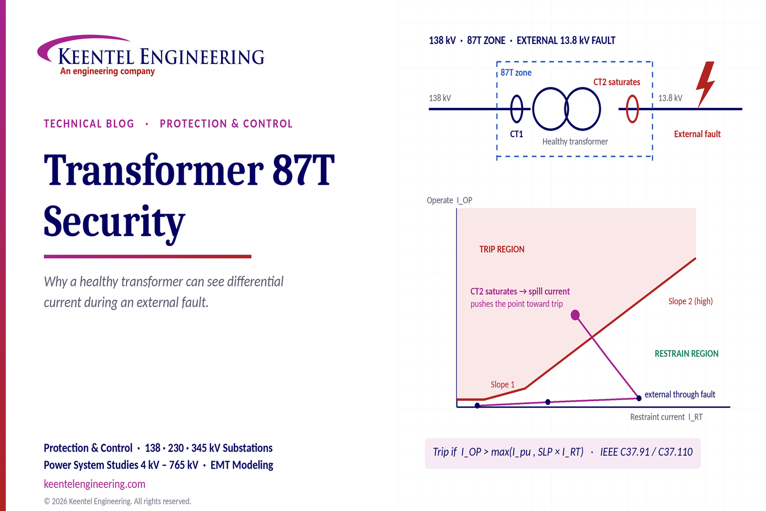
Learn why transformer differential relays detect current during external faults, how CT saturation causes spill current, and how secure 87T protection prevents trips.
By SANDIP R PATEL
•
October 10, 2026
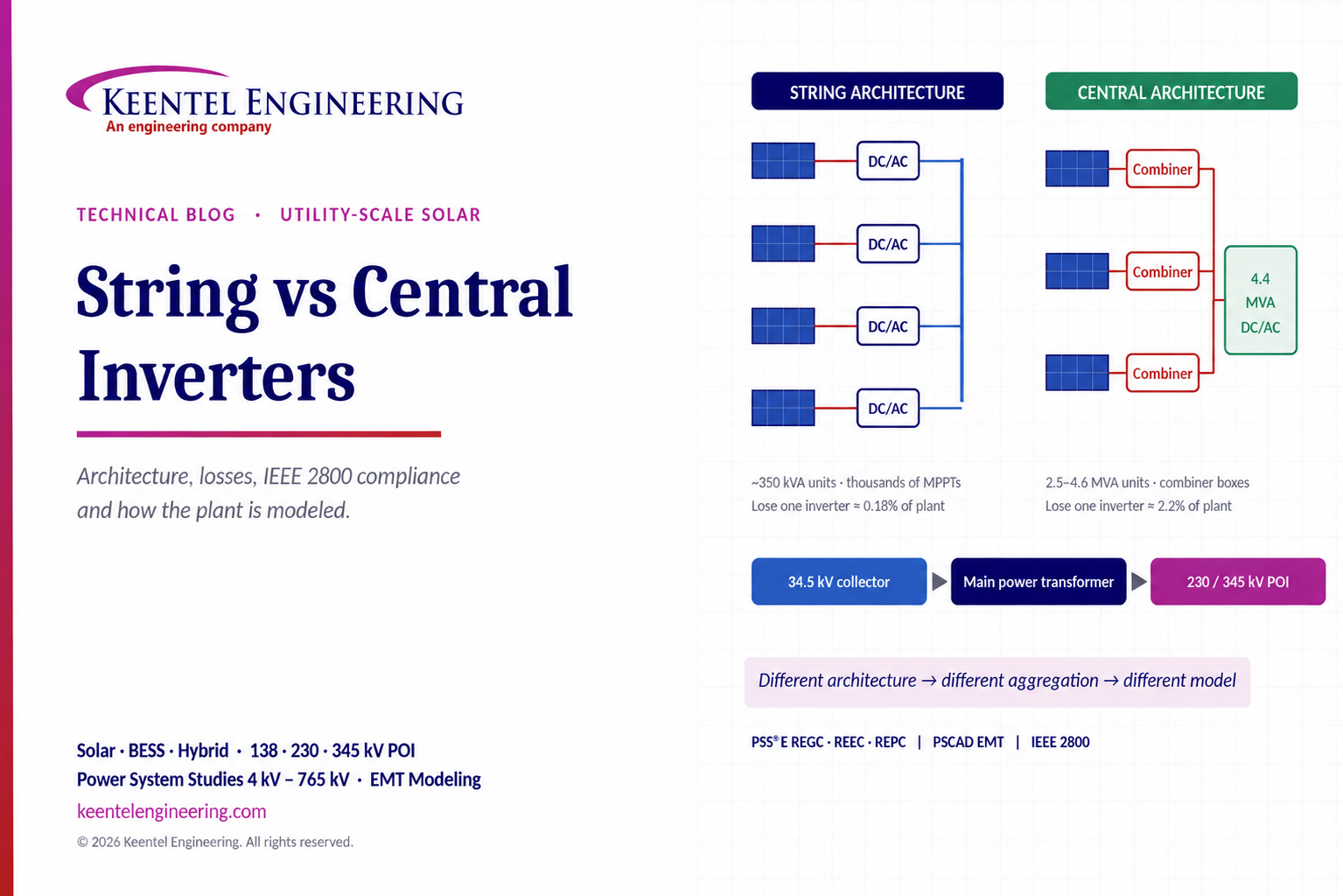
Compare string vs central inverters for utility-scale solar, including efficiency, maintenance, grid compliance, reactive power and interconnection studies.

By SANDIP R PATEL
•
October 3, 2026
Engineering guide to PRC-028 disturbance recording, PRC-029 ride-through and PRC-030 event detection for inverter-based resources.

By SANDIP R PATEL
•
October 3, 2026
A practical guide to SSO classification, SSR, PEDI, Wind-SSCI, EMT analysis, mitigation and protection based on CIGRE TB 909.

By SANDIP R PATEL
•
October 3, 2026
Learn ERCOT generator testing for PFR, MOD-025 and MOD-026/027, including staged tests, capability verification, dynamic models and field testing.

By SANDIP R PATEL
•
October 3, 2026
Learn how PV string I-V curve testing identifies hidden solar performance losses, including soiling, shading, mismatch, degradation, and wiring faults.





