
A Coordinated Electric System Interconnection Review—the utility’s deep-dive on technical and cost impacts of your project.
Challenge: Frequent false tripping using conventional electromechanical relays
Solution: SEL-487E integration with multi-terminal differential protection and dynamic inrush restraint
Result: 90% reduction in false trips, saving over $250,000 in downtime
PRC-006-5 NERC Compliance Services Content Library
Aug 11, 2026 | Blog
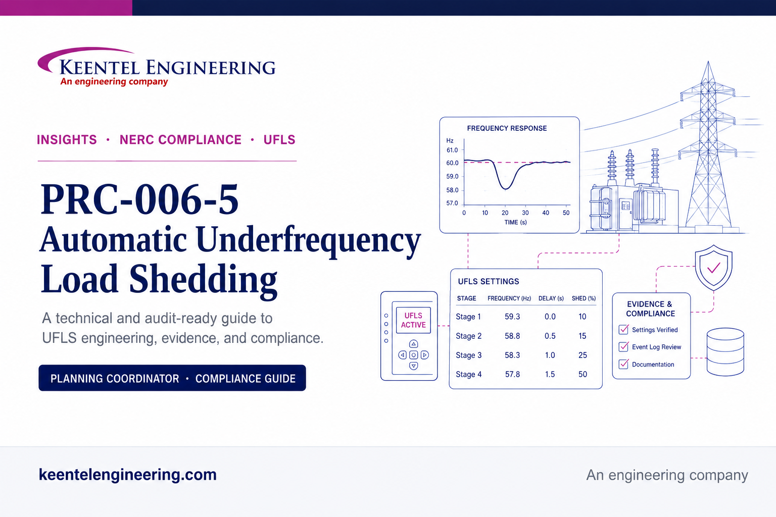
A technical and audit-ready guide to Automatic Underfrequency Load Shedding compliance and Keentel Engineering support services
Executive overview
PRC-006-5 addresses a narrow but critical reliability problem: how an electrical island should arrest a severe frequency decline, stabilize within acceptable limits, and preserve as much of the system as practicable when generation and load are suddenly out of balance. The standard does this by requiring a coordinated automatic underfrequency load shedding program supported by documented island criteria, dynamic simulation, field implementation, database maintenance, event assessment, and corrective action governance.
For compliance leaders, the central challenge is that PRC-006-5 is not satisfied by a single relay-setting file or a five-year study report. Compliance depends on an interconnected chain of controls. The Planning Coordinator must define the planning basis, identify islands, demonstrate performance, coordinate with other Planning Coordinators, maintain model-ready data, and act on event or assessment deficiencies. UFLS entities and Transmission Owners must provide accurate data and implement the program in the field. Every link must be supported by dated, traceable evidence.
Keentel Engineering supports that full chain. Its NERC compliance services combine technical engineering review, requirement-by-requirement gap assessment, RSAW narrative development, evidence architecture, mock-audit preparation, corrective action planning, and configurable NERC compliance software. The objective is not merely to assemble documents before an audit. The objective is to build a repeatable compliance system in which engineering conclusions, field configurations, ownership, dates, approvals, and evidence remain aligned throughout the compliance cycle.
Keentel Engineering perspective
A defensible PRC-006-5 program connects four disciplines that are often managed separately: system planning, protection and control, compliance governance, and records management. Audit risk rises when any one of these disciplines works from a different data set, schedule, or interpretation.
Why automatic underfrequency load shedding matters
System frequency is an immediate indicator of the balance between generation and electrical demand. When an island loses generation or separates with insufficient generation, frequency can decline rapidly. Governor response, available reserves, load-frequency characteristics, and other controls may slow the decline, but a sufficiently severe imbalance can progress toward generator tripping, voltage stress, equipment exposure, and uncontrolled collapse. UFLS is therefore a last-resort preservation measure rather than a routine operating tool.
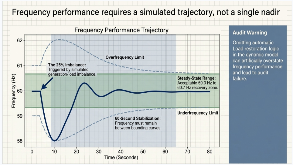
PRC-006-5 requires the UFLS design to be tested against underfrequency conditions resulting from an imbalance of up to 25 percent within identified islands. The design must keep simulated frequency between the applicable underfrequency and overfrequency performance characteristics for the prescribed duration or until an acceptable steady state is reached. It must also limit excessive volts-per-hertz exposure at specified generator and generator step-up transformer buses. These technical criteria connect load shedding design to both frequency recovery and equipment protection.
1: Frequency performance: the simulated response must remain above the underfrequency performance characteristic and below the overfrequency performance characteristic for 60 seconds or until the defined steady-state condition is reached
2: Steady-state range: the general requirement uses a range from 59.3 Hz to 60.7 Hz, subject to applicable regional variance provisions
3: V/Hz exposure: 1.18 per unit may not be exceeded for longer than two cumulative seconds per simulated event, and 1.10 per unit may not be exceeded for longer than 45 cumulative seconds per simulated event at the specified buses
4:
Modeling completeness: applicable underfrequency and overfrequency generator trip settings and automatic load restoration that affects stabilization must be represented in the design assessment
Applicability and accountability
PRC-006-5 assigns different responsibilities to different functional roles. The Planning Coordinator establishes and assesses the program. UFLS entities implement automatic load tripping and provide data. Transmission Owners may also be responsible for automatic switching of existing capacitor banks, transmission lines, and reactors when the UFLS program requires those actions to control over-voltage following load shedding.
| Role | Primary requirement coverage | Core accountability |
|---|---|---|
| Planning Coordinator | R1-R7 and R11-R15, subject to regional variance | Planning basis, island identification, UFLS program design, dynamic assessment, coordination, database maintenance, event assessment, comments, and corrective action planning |
| UFLS entity | R8-R9 | Provide data in the Planning Coordinator format and schedule; implement automatic tripping of Load according to the UFLS program and any Corrective Action Plan |
| Transmission Owner | R10 and potentially R8-R9 when also a UFLS entity | Implement required automatic switching for over-voltage control and retain dated settings or logic evidence |
| Compliance and records teams | Supports all applicable requirements | Maintain ownership, dates, approvals, evidence retention, audit narratives, and response packages |
Applicability caution
Registration alone does not answer every PRC-006-5 question. A registered entity may have multiple roles, assets in more than one Planning Coordinator area, or obligations established by the Planning Coordinator UFLS program. Applicability should be documented at the requirement and asset leve
PRC-006-5 requirement map
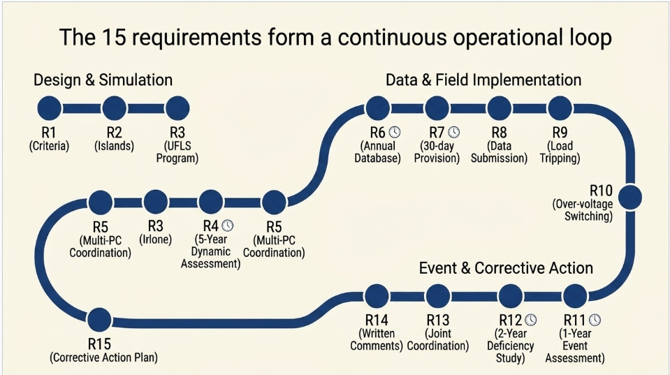
| Req | Owner | Control objective | Critical timing |
|---|---|---|---|
| R1 | PC | Document criteria for selecting BES portions that may form islands | Criteria current and approved |
| R2 | PC | Identify study islands, planned islands, and regional/interconnection basis islands | Whenever planning basis changes |
| R3 | PC | Develop a compliant UFLS program and implementation schedule | Program lifecycle |
| R4 | PC | Conduct and document a dynamic UFLS design assessment | At least once every five years |
| R5 | PC | Coordinate design for islands spanning multiple PC areas | When multi-PC island applies |
| R6 | PC | Maintain a model-ready UFLS database | Each calendar year; no more than 15 months |
| R7 | PC | Provide the database to another PC upon request | Within 30 calendar days |
| R8 | UFLS entity | Provide data in the requested format and schedule | Per PC request |
| R9 | UFLS entity | Implement automatic Load tripping | Per program and CAP schedule |
| R10 | TO | Implement required automatic switching for over-voltage control | Per program and CAP schedule |
| R11 | PC | Assess qualifying BES islanding events | Within one year of event actuation |
| R12 | PC | Assess design after event deficiencies are identified | Within two years of event actuation |
| R13 | PC | Coordinate multi-PC event assessments | For qualifying multi-PC events |
| R14 | PC | Respond to written comments before finalization | Before final UFLS program action |
| R15 | PC | Develop a CAP and implementation schedule when performance is not met | Within the applicable R4 or R12 timeframe |
Detailed interpretation of R1 through R15
The following sections translate each requirement into an operating control, an evidence expectation, and a practical Keentel Engineering service opportunity.
The discussion is intentionally broader than the minimum Measure language because audit defensibility depends on traceability, not only on possession of a final document.
R1 - Criteria for selecting portions of the BES that may form islands
Primary responsible role: Planning Coordinator
What the requirement establishes: R1 requires documented criteria that consider both historical events and system studies when selecting BES portions, including relevant interconnected portions in adjacent Planning Coordinator and Regional Entity areas, that may form islands.
Technical execution: A strong R1 methodology explains the topology conditions, protection or remedial action behavior, credible separation points, generation-load balance concerns, and historical experience used to screen potential islands. The criteria should be reproducible. A reviewer should be able to apply the methodology and understand why a portion of the BES was included or excluded.
Audit and evidence focus: Common weaknesses include a study report with no formal criteria, a historical-event reference with no retained analysis, and a methodology that does not address adjacent areas. Evidence should include the approved criteria, source studies, historical-event review, revision history, and ownership.
How Keentel Engineering supports
the requirement: Keentel Engineering can facilitate criteria workshops, document the methodology, map source studies and events, and configure a controlled evidence package so the basis remains traceable through future R2 and R4 activities.
R2 - Identification of islands used to design the UFLS program
Primary responsible role: Planning Coordinator
What the requirement establishes: R2 requires the Planning Coordinator to identify one or more islands based on the R1 criteria, include portions designed to detach through relay schemes or Special Protection Systems, and include the required regional or interconnection basis island. Adjusted boundaries require mutual consent when used to produce contiguous regional islands suitable for simulation.
Technical execution: The island record should connect one-line diagrams, model topology, planning criteria, planned-island logic, and the simulation case naming convention. The same island should not be described differently across the criteria document, study report, UFLS program, and evidence index.
Audit and evidence focus: Audit risk arises when island boundaries exist only inside a simulation case, planned islands are omitted, or mutual-consent evidence cannot be produced. Maps, topology diagrams, memoranda, and dated coordination communications are valuable evidence.
How Keentel Engineering supports
the requirement: Keentel Engineering can reconcile island definitions across documents and models, create an island register, and develop a traceability matrix linking each island to R1 criteria, planned schemes, study cases, and approvals.
R3 - Development of a UFLS program that meets performance characteristics
Primary responsible role: Planning Coordinator
What the requirement establishes: R3 requires a UFLS program, notification, and an implementation schedule that meet the frequency and V/Hz performance characteristics for simulated imbalance scenarios of up to 25 percent within each identified island.
Technical execution: The program design normally includes load blocks, frequency thresholds, time delays, load composition assumptions, expected generation response, restoration philosophy, and any related voltage-control actions. The engineering report should preserve the complete performance envelope, not only the lowest frequency value. It should show the trajectory relative to both performance curves and calculate cumulative V/Hz exposure at every required bus.
Audit and evidence focus: Typical failure points include incomplete V/Hz documentation, unclear scenario selection, missing notification evidence, and an implementation schedule that is not tied to specific UFLS entities. Passing plots without reproducible inputs may not be sufficient.
How Keentel Engineering supports
the requirement: Keentel Engineering can review scenario coverage, performance calculations, report structure, implementation schedules, and notification records, then convert the program into an auditable control-and-evidence package.
R4 - Five-year dynamic UFLS design assessment
Primary responsible role: Planning Coordinator
What the requirement establishes: R4 requires a documented dynamic
assessment at least once every five years for every R2 island. The simulation must model applicable underfrequency and overfrequency generator trip settings and any automatic Load restoration that affects stabilization during the simulated period.
Technical execution: R4 requires disciplined model governance. The Planning Coordinator should know which individual units exceed 20 MVA, which plants or facilities exceed 75 MVA in aggregate, which common-bus facilities exceed 75 MVA, which trip settings cross the modeling curves, and which restoration schemes operate during the study window. Input data should be dated, validated, and tied to the model version used in each case.
Audit and evidence focus: A frequent weakness is a polished final report that cannot demonstrate the completeness of the generator inventory, the origin of trip settings, the treatment of restoration, or the software and model versions. The five-year clock also requires explicit scheduling.
How Keentel Engineering supports
the requirement: Keentel Engineering can establish the study data request, model inventory, assumptions register, simulation QA/QC, performance review, and final evidence map needed to support M4.
R5 - Coordination when an island spans multiple Planning Coordinator areas
Primary responsible role: Planning Coordinator
What the requirement establishes: R5 requires coordination with every other Planning Coordinator whose area or portion of area is included in the same identified island. The standard permits a common program, a joint assessment, or an independent assessment with required recommendations when performance is not met.
Technical execution: Coordination must extend beyond attendance at meetings. Study assumptions, topology, dynamic models, event definitions, load shedding behavior, conclusions, and recommended modifications should be aligned or differences should be formally handled.
Audit and evidence focus: Meeting invitations alone rarely establish the substance of coordination. Strong evidence includes agreed assumptions, joint reports, comment logs, decision records, recommendation letters, and dated communications to affected Planning Coordinators and the ERO when required.
How Keentel Engineering supports the requirement: Keentel Engineering can organize the coordination record, document decisions and open items, manage versioned comments, and prepare a defensible narrative showing how the selected R5 pathway was completed.
R6 - Annual maintenance of the UFLS database
Primary responsible role: Planning Coordinator
What the requirement establishes: R6 requires a database containing the data necessary to model the UFLS program for event analyses and assessments. Maintenance must occur at least once each calendar year with no more than 15 months between maintenance activities.
Technical execution: The database should include enough information to reproduce the program in a dynamic study and understand actual implementation. Typical fields include entity, station, feeder or load block, frequency threshold, time delay, armed Load, relay or logic reference, status, effective date, and data-source metadata.
Audit and evidence focus: The rolling 15-month limit creates risk even when an update occurs in every calendar year. Other weaknesses include untracked spreadsheet revisions, missing validation, and a database that does not reconcile to R9 field evidence.
How Keentel Engineering supports the requirement: Keentel Engineering can define the data model, normalize submissions, implement validation rules, configure annual workflow reminders, and preserve current and prior-year evidence.
R7 - Provision of the UFLS database to other Planning Coordinators
Primary responsible role: Planning Coordinator
What the requirement establishes: R7 requires the Planning Coordinator to provide its UFLS database to another Planning Coordinator within the same Interconnection within 30 calendar days of a request.
Technical execution: A controlled process should log the request date, scope, assigned owner, data version, security method, transmission date, and acknowledgement. The transmitted database should match the controlled source or clearly identify any permitted redaction or format conversion.
Audit and evidence focus: The most common issue is not the database itself but the absence of a dated request-and-response record proving the 30-day requirement was met.
How Keentel Engineering supports the requirement: Keentel Engineering can configure request intake, deadline calculation, approval, secure transmittal evidence, and automatic retention within NERC compliance software.
R8 - UFLS entity data submission to the Planning Coordinator
Primary responsible role: UFLS entity
What the requirement establishes: R8 requires each UFLS entity to submit data in the format and on the schedule specified by its Planning Coordinator to support maintenance of the UFLS database.
Technical execution: The UFLS entity should control the source of each field and validate that feeder status, armed Load, relay settings, and implementation dates are current. A submission that is timely but not in the specified format can still create compliance exposure.
Audit and evidence focus: Common weaknesses include missing transmittal evidence, late internal review, inconsistent naming, empty required fields, and inability to reproduce the submitted file.
How Keentel Engineering supports the requirement: Keentel Engineering can establish data-owner workflows, pre-submission validation, change control, and an evidence package that includes the request, completed file, approval, transmission, and acknowledgement.
R9 - Automatic tripping of Load in accordance with the UFLS program
Primary responsible role: UFLS entity
What the requirement establishes: R9 requires the UFLS entity to provide automatic tripping of Load according to the Planning Coordinator program, implementation schedule, and any Corrective Action Plan in every applicable Planning Coordinator area where it owns assets.
Technical execution: R9 is the field implementation bridge. The controlled program should reconcile to actual feeder assignments, relay settings, logic enablement, armed Load values, one-line diagrams, maintenance status, and approved deviations. The denominator used to calculate implementation percentage should be clear and reproducible.
Audit and evidence focus: Installed hardware is not enough. Auditors may examine whether the scheme was enabled, whether settings match the program, whether Load values are current, and whether CAP milestones were completed. Dated feeder spreadsheets, settings, commissioning records, and field verification support the Measure.
How Keentel Engineering supports the requirement: Keentel Engineering can perform program-to-field reconciliation, settings review, sample-based verification, implementation percentage checks, and evidence indexing.
R10 - Automatic switching to control over-voltage after UFLS operation
Primary responsible role: Transmission Owner
What the requirement establishes: R10 applies when the UFLS program requires automatic switching of existing capacitor banks, transmission lines, or reactors to control over-voltage resulting from load shedding.
Technical execution: The Transmission Owner should document the applicability decision, required devices, initiating logic, timing, permissives, blocking conditions, and coordination with the UFLS program. As-built logic and tested settings should match the approved design.
Audit and evidence focus: A common weakness is assuming R10 is not applicable without retaining the Planning Coordinator determination or technical basis. Where it is applicable, missing functional testing and outdated logic diagrams are significant risks.
How Keentel Engineering supports the requirement: Keentel Engineering can document applicability, review switching logic, map design to as-built evidence, and establish a controlled test-and-approval package.
R11 - Assessment of a qualifying BES islanding event
Primary responsible role: Planning Coordinator
What the requirement establishes: R11 is triggered when a BES islanding event in the Planning Coordinator area causes system frequency to move below the UFLS program initializing set points. The event must be assessed within one year to evaluate both equipment performance and program effectiveness.
Technical execution: Equipment performance asks whether relays, logic, communications, and breakers acted as expected. Program effectiveness asks whether the overall design arrested the decline, supported recovery, limited adverse effects, and behaved consistently with the modeled program. These are related but distinct analyses.
Audit and evidence focus: A disturbance report that only reconstructs the event may not satisfy R11. The report should state the trigger, data sources, expected versus actual UFLS response, equipment findings, program-level conclusions, and identified deficiencies.
How Keentel Engineering supports the requirement: Keentel Engineering can establish an event data plan, build the frequency and operation timeline, compare expected and actual behavior, and prepare the dated assessment and supporting evidence.
R12 - Design assessment when event deficiencies are identified
Primary responsible role: Planning Coordinator
What the requirement establishes: R12 requires a documented UFLS design assessment within two years of event actuation when the R11 assessment identifies program deficiencies.
Technical execution: The follow-up assessment should convert event findings into revised assumptions and cases. It should show how each deficiency was represented, whether the program meets R3 after proposed changes, and which changes require a Corrective Action Plan under R15.
Audit and evidence focus: Weaknesses include closing the event report without a formal deficiency decision, starting the two-year clock from the wrong date, or performing a general study that does not specifically consider the identified deficiencies.
How Keentel Engineering supports the requirement: Keentel Engineering can maintain the deficiency register, develop the study scope, update models, map conclusions to R15, and track the two-year deadline.
R13 - Coordination of multi-Planning Coordinator event assessments
Primary responsible role: Planning Coordinator
What the requirement establishes: R13 applies when the qualifying islanding event includes areas or portions of areas of other Planning Coordinators. The affected Planning Coordinators must coordinate through a joint assessment or one of the permitted independent-assessment pathways.
Technical execution: The coordination record should compare data, timelines, equipment operations, model assumptions, conclusions, and recommendations. If conclusions differ, likely causes must be identified and reported as required.
Audit and evidence focus: Separate reports with no documented comparison are a common weakness. Evidence should show substantive coordination and disposition of differences, not merely distribution of final reports.
How Keentel Engineering supports the requirement: Keentel Engineering can facilitate a common event evidence set, comparison matrix, coordinated conclusions, and required reporting.
R14 - Written responses to comments before finalizing the UFLS program
Primary responsible role: Planning Coordinator
What the requirement establishes: R14 requires written responses to written comments submitted by UFLS entities and Transmission Owners following a comment period and before finalizing the UFLS program, design assessment, or data-submittal format and schedule.
Technical execution: A formal comment-disposition process should identify the commenter, issue, affected document, technical evaluation, decision, resulting change, approval, and response date.
Audit and evidence focus: Verbal discussion or meeting minutes do not replace the required written response. Another risk is issuing the response after finalization or failing to explain why a change was not made.
How Keentel Engineering supports the requirement: Keentel Engineering can operate a controlled comment log, prepare technical dispositions, maintain versions, and demonstrate that responses preceded finalization.
R15 - Corrective Action Plan and implementation schedule
Primary responsible role: Planning Coordinator
What the requirement establishes: R15 is triggered when an R4, R5, or R12 design assessment determines that the UFLS program does not meet R3 performance characteristics. The Planning Coordinator must develop a dated Corrective Action Plan and schedule for implementation by UFLS entities within the applicable assessment timeframe.
Technical execution: A defensible CAP identifies the specific deficiency, technical remedy, affected entities and assets, responsible owners, engineering dependencies, interim risk controls, milestones, evidence required for completion, and closure criteria. The schedule must be realistic yet aligned to the standard timeframe.
Audit and evidence focus: Common weaknesses include informal remediation lists, missing implementation dates, unclear ownership, milestones without evidence, and closure based on planned rather than completed work.
How Keentel Engineering supports the requirement: Keentel Engineering can draft the CAP, build an implementation evidence plan, configure milestone governance in compliance software, and perform closure verification.
Technical deep dive on R3 and R4
1: Scenario design and the 25 percent imbalance
The imbalance is defined using Load and actual generation output within the island. A strong study process does more than run one case at the maximum imbalance. It establishes a scenario matrix that captures different island sizes, generation compositions, Load levels, governor response, protection behavior, and restoration assumptions. The scenario register should explain why each case is credible and which case is expected to be limiting.
1: Define the island topology and initial operating point
2: Document the generation loss or separation mechanism and calculate the resulting imbalance
3: Identify the UFLS stages, thresholds, delays, and Load quantities represented in the model
4: Document generation controls, frequency-dependent Load behavior, and other dynamic assumptions
5: Run sensitivity cases where uncertainty could change performance conclusions
6: Retain the case files, input versions, output traces, and engineering disposition
2: Frequency performance is a trajectory, not a single number
A minimum frequency value is important, but the standard evaluates whether the entire simulated trajectory remains within the underfrequency and overfrequency performance characteristics. The analysis should preserve time-series plots and, ideally, an automated pass/fail calculation showing the margin to each curve. The report should also explain how the steady-state condition was determined and whether the simulation ended because the 60-second duration was reached or because the defined steady state was achieved.
3: V/Hz calculations require bus-level traceability
V/Hz must be evaluated at the generator bus and generator step-up transformer high-side bus associated with the specified unit and facility thresholds. The analysis should identify every applicable bus, calculate per-unit voltage divided by per-unit frequency, and accumulate the time above each threshold. A single system-level voltage plot is generally not a substitute for bus-level cumulative-duration evidence.
1: Build the list of applicable units, plants, facilities, and common-bus aggregations
2: Map each applicable generator to the modeled generator bus and GSU high-side bus
3: Calculate the V/Hz trace using consistent per-unit bases
4: Calculate cumulative time above 1.18 per unit and above 1.10 per unit
5: Retain a result table showing pass/fail status for every bus and scenario
6: Investigate limiting buses and document design changes or CAP actions when necessary
4: Generator trip-setting model governance
R4 does not require every generator trip setting to be modeled. It requires modeling of applicable settings relative to the Attachment 1 generator underfrequency and overfrequency trip modeling curves. This creates a data-governance problem: the Planning Coordinator needs a complete inventory, a threshold determination, and a record of which settings were included or excluded and why. Facility aggregation rules also need to be applied consistently.
5: Automatic Load restoration can change the conclusion
Restoration that occurs during the simulation can reintroduce Load before frequency is fully stabilized. If restoration logic is omitted, the model may overstate performance. The assessment should identify automatic restoration schemes, timing, reset behavior, blocking conditions, and the Load quantity restored. Where no automatic restoration affects the study interval, the evidence should document how that conclusion was reached.
Evidence retention and RSAW readiness
The compliance section of PRC-006-5 assigns different retention expectations by requirement. A sustainable program should translate these expectations into an evidence schedule rather than rely on staff memory. The evidence system should distinguish current controlled evidence, evidence since the last audit, prior-year database evidence, transmittal records, and six-year event evidence.
| Requirement group | Owner | Retention focus |
|---|---|---|
| R1, R2, R3, R4, R5, R12, R14, R15 | Planning Coordinator | Current evidence plus evidence needed to show compliance since the last audit |
| R6 | Planning Coordinator | Current UFLS database update evidence plus the prior year update |
| R7 | Planning Coordinator | Database transmittal evidence since the last audit |
| R8 | UFLS entity | Data transmittal evidence since the last audit |
| R9 | UFLS entity | Current adherence evidence plus adherence evidence since the last audit |
| R10 | Transmission Owner | Current adherence evidence plus adherence evidence since the last audit |
| R11 and R13 | Planning Coordinator | Six calendar years |
An effective RSAW response should tell a coherent story. It should identify the control owner, describe the process in the entity's own words, map each statement to specific evidence, and explain how the evidence demonstrates every part of the requirement. A long list of files without a narrative can make a compliant program difficult to audit. Conversely, a strong narrative cannot cure missing or contradictory evidence.
1: Prepare one applicability statement for each requirement and regional variance
2: Write a concise compliance narrative describing who performs the control, when it occurs, how it is approved, and where evidence is retained
3: Map each requirement part to one or more evidence items
4: Confirm that evidence is dated, final, approved, and consistent with related requirements
5: Perform a mock auditor challenge using the expected evidence and technical questions
6:
Create an audit export that contains only the approved files and index needed to answer the request
Regional variances
Quebec Interconnection
The Quebec Interconnection variance replaces R3 and R4 in their entirety with D.A.3 and D.A.4. The variance uses specified extreme events rather than the general imbalance formulation, uses the Attachment 1A curves, permits a steady-state frequency range down to 59.0 Hz, and applies Quebec-specific BES generator treatment. A Quebec applicability review should therefore begin with the variance, not the general R3 and R4 text.
Western Interconnection
The Western Interconnection variance replaces R1 through R5 and R11 through R15 with coordinated requirements D.B.1 through D.B.4 and D.B.11 through D.B.12. It emphasizes joint regional review, a Western Interconnection-wide coordinated UFLS program, coordinated five-year design assessment, and coordinated event assessment. Base requirements R6 through R10 remain important for database, data submission, field implementation, and over-voltage switching responsibilities.
Regional governance risk
The applicable requirement number changes under a variance, but the underlying audit themes remain: documented criteria, complete modeling, substantive coordination, dated evidence, field implementation, event analysis, and corrective action governance.
A sustainable compliance operating model
PRC-006-5 becomes easier to manage when converted from a collection of periodic tasks into a lifecycle with named owners and recurring controls. Keentel Engineering recommends an operating model that connects the five-year assessment cycle, annual database cycle, field implementation process, stakeholder comment process, event triggers, and CAP workflow.
1: Governance layer: assign a standard owner, requirement owners, technical approvers, evidence custodians, and executive escalation path
2: Technical layer: control island definitions, study assumptions, dynamic models, generator trip-setting inventories, restoration models, field settings, and implementation status
3: Compliance layer: maintain applicability, narratives, evidence maps, retention rules, due dates, and audit request procedures
4: Coordination layer: preserve Planning Coordinator, UFLS entity, Transmission Owner, Regional Entity, and ERO communications and decisions
5:
Improvement layer: track deficiencies, recommendations, CAP milestones, verification, and closure evidence
Keentel Engineering PRC-006-5 compliance services
Keentel Engineering can support a focused requirement, a full PRC-006-5 program review, or an integrated multi-standard NERC compliance transformation. The service model is designed to translate engineering work into audit-ready compliance evidence without weakening technical rigor.
| Service area | Representative deliverables |
|---|---|
| Applicability and gap assessment | Requirement and regional-variance applicability, existing control review, evidence inventory, risk ranking, remediation plan |
| UFLS engineering support | Island basis review, study scope, scenario matrix, performance analysis, V/Hz review, trip-setting model governance, restoration review |
| RSAW and audit readiness | Compliance narratives, evidence mapping, auditor question preparation, mock audit, response package quality control |
| Database and field reconciliation | R6 data model, R8 submission workflow, R9 feeder and relay reconciliation, R10 applicability and logic evidence |
| Event and CAP support | R11 event assessment, R12 deficiency study, R13 coordination, R14 comment disposition, R15 CAP and closure verification |
| Program governance | RACI, annual calendar, five-year schedule, retention matrix, procedures, training, management reporting |
Keentel NERC compliance software for PRC-006-5
Keentel Engineering's NERC compliance software framework is designed to support the evidence and workflow requirements that spreadsheets and shared drives often handle inconsistently. Software does not replace engineering judgment or prove compliance by itself. It creates control over ownership, dates, versions, approvals, dependencies, and audit retrieval.
1: Requirement workspace: maintain applicable requirement text, entity interpretation, control owner, compliance narrative, and related procedures
2: Evidence map: link every requirement part to controlled evidence with date, version, approval, retention category, and confidentiality metadata
3: Compliance calendar: track the five-year R4 cycle, annual R6 updates, the 15-month limit, R7 30-day requests, R11 one-year events, R12 two-year studies, and R15 CAP milestones
4: Data request workflow: issue, receive, validate, approve, and retain R8 submissions and supporting acknowledgements
5: Field implementation register: reconcile UFLS program requirements to feeder assignments, relay settings, armed Load, testing, and effective dates
6: Coordination log: preserve comments, meetings, decisions, recommendations, responses, and approvals for R5, R13, and R14
7: CAP management: assign owners, dependencies, milestones, evidence, status, risk, and closure criteria
8: Audit export: produce a controlled RSAW narrative and evidence index without exposing unrelated files
Software design principle
The system should make the compliant path the normal path. Each recurring task should automatically create the expected approval, evidence, metadata, and reminder rather than depend on a separate manual records exercise.
A 90-day PRC-006-5 readiness roadmap
| Period | Primary activities |
|---|---|
| Days 1-15 | Confirm roles, Planning Coordinator areas, regional variance, requirement applicability, existing procedures, and key technical owners |
| Days 16-30 | Inventory R1-R15 evidence, study models, database files, field settings, event records, CAPs, and prior audit responses |
| Days 31-45 | Evaluate island criteria, study completeness, V/Hz results, trip-setting inventories, restoration treatment, and field reconciliation |
| Days 46-60 | Rank gaps by violation risk and operational significance, define corrective actions, owners, dates, and interim controls |
| Days 61-75 | Configure software workflows, evidence metadata, calendars, request timers, comment logs, and CAP tracking |
| Days 76-90 | Finalize RSAW narratives, conduct a mock audit, resolve inconsistencies, approve the evidence package, and establish the recurring compliance calendar |
Conclusion and next step
PRC-006-5 is a system-preservation standard with equally demanding engineering and evidence expectations. A Planning Coordinator can have a technically capable UFLS design and still face audit exposure if island criteria, model data, coordination, implementation schedules, or corrective actions are not traceable. A UFLS entity can have relays in service and still face exposure if the field configuration cannot be reconciled to the Planning Coordinator program and dated evidence.
Keentel Engineering helps close that gap by combining power-system engineering, NERC compliance services RSAW readiness, and configurable NERC compliance software. The resulting program is easier to operate, easier to explain, and easier to defend because every technical conclusion is connected to an owner, an approval, a deadline, and evidence.
Call to action
Schedule a PRC-006-5 readiness assessment with Keentel Engineering to evaluate applicability, technical study completeness, evidence quality, field implementation, event and CAP governance, and opportunities to automate recurring compliance workflows.
Anonymous Composite PRC-006-5 Case Studies
Planning Coordinator UFLS Program and Audit Readiness
Island basis, five-year design assessment, coordination evidence, RSAW preparation, and sustainable compliance governance
Case study at a glance
| Case study element | Anonymous composite profile |
|---|---|
| Entity context | A Planning Coordinator responsible for a multi-entity UFLS program and periodic dynamic assessment |
| Primary requirements | R1, R2, R3, R4, R5, R14, and R15 |
| Primary risk | Technically useful studies existed, but island definitions, model inputs, coordination, and evidence were not consistently traceable |
| Keentel service focus | Engineering gap assessment, study governance, evidence architecture, RSAW readiness, and CAP workflow |
| Software focus | Requirement mapping, evidence control, five-year calendar, coordination log, comment disposition, and CAP milestones |
Background
The anonymous Planning Coordinator maintained a mature UFLS program and had completed previous frequency studies. The engineering team understood the system and had extensive technical records. The compliance team, however, found that the records had evolved over several study cycles, multiple staff changes, and separate document repositories. The primary concern was not the absence of engineering work. It was whether the organization could demonstrate a complete, consistent, and timely compliance chain from R1 criteria through R4 assessment and any resulting R15 actions.
A planned audit-readiness review also identified that the same island was described with different names and boundary conventions in a methodology, a dynamic model case, and a stakeholder presentation. Some coordination decisions were preserved only in long e-mail threads. The final assessment report contained frequency plots but did not present a complete bus-by-bus V/Hz table or a transparent disposition of generator trip settings relative to the Attachment 1 modeling curves.
Initial risk findings
1: R1 criteria referred to system studies and historical events but did not show a controlled mapping from each criterion to the supporting study or event record
2: R2 island definitions were technically similar but not identical across the island register, one-line diagrams, model cases, and final report
3: R3 performance evidence focused on frequency nadir and recovery but did not provide a complete cumulative V/Hz result table for every required bus and scenario
4: R4 source data did not include one controlled inventory showing all applicable generators, plant aggregates, common-bus aggregates, trip-setting source dates, and modeling dispositions
5: Automatic Load restoration was discussed in engineering notes but not clearly identified as modeled, not modeled, or not applicable for each island and scenario
6: R5 coordination was substantial in practice but difficult to prove because assumptions, decisions, comments, and recommendations were distributed across e-mail and meeting records
7: R14 comment responses were available, but the evidence package did not clearly demonstrate that each written response occurred before program finalization
8: Potential R15 corrective actions did not yet have a standardized CAP template, evidence plan, or software-controlled closure criteria
Keentel Engineering approach
Phase 1: Requirement and evidence architecture
Keentel Engineering structured the review around the exact control chain rather than around existing folders. Each R1 through R5, R14, and R15 part was mapped to an owner, process, technical record, approval, date, and retention requirement. The team created a single evidence index and marked records as authoritative, supporting, superseded, or missing.
1: Confirmed requirement applicability, regional variance status, island scope, and multi-PC coordination triggers
2: Created a requirement-to-evidence matrix that separated final evidence from supporting calculations and working papers
3: Established a controlled naming convention for islands, study cases, model versions, and final reports
4: Identified inconsistencies requiring technical resolution rather than document-only correction
Phase 2: Technical study governance
The engineering workstream focused on reproducibility. The team did not simply reformat the final report. It rebuilt the study traceability needed to explain the technical conclusions under audit.
1: Linked each R1 criterion to historical-event and study support
2: Reconciled R2 island maps, one-line diagrams, model topology, and case names
3: Reviewed the R3 scenario matrix and verified that the up-to-25-percent imbalance basis was documented
4: Developed a V/Hz results register showing every applicable generator bus and GSU high-side bus, threshold, cumulative duration, and pass/fail result
5: Built a generator trip-setting inventory with size, connection, aggregation, setting source, curve comparison, and modeling disposition
6: Documented automatic Load restoration applicability and modeling treatment by scenario
7: Established independent engineering review and signoff for assumptions, results, and final conclusions
Phase 3: Coordination, comments, and audit readiness
Keentel Engineering converted informal coordination into a structured record without recreating decisions that had not occurred. Existing e-mails, meeting minutes, markups, and reports were indexed by issue and date. Open technical differences were assigned for resolution. Written comments and responses were linked to the version that was ultimately finalized.
1: Created an R5 coordination matrix covering assumptions, models, results, recommendations, and final agreement
2: Created an R14 comment-disposition log showing commenter, issue, technical evaluation, decision, response date, resulting change, and finalization date
3: Prepared requirement-specific RSAW narratives written in the entity's own process language
4: Conducted a mock audit using expected auditor questions and evidence challenges
5: Created an R15 CAP template with milestones, dependencies, evidence expectations, verification, and closure approval
How NERC compliance software supported the control model
The software configuration was organized around the recurring compliance cycle. It was not used as a generic document repository. Each requirement had a control owner, narrative, due date logic, evidence map, approval, and status. The five-year assessment included interim milestones for data requests, model freeze, simulation, review, stakeholder comments, finalization, and CAP determination.
1: R1 and R2 records were linked to controlled island and criteria registers
2: R3 and R4 evidence was linked to model versions, assumptions, result registers, and approvals
3: R5 coordination items were assigned, dated, and closed with supporting evidence
4: R14 comments could not be closed without a written response and disposition
5: R15 CAP milestones required approved evidence before completion status was accepted
6: The audit export produced the narrative, index, and approved evidence without exposing working drafts
Representative deliverables
1: PRC-006-5 applicability and responsibility matrix
2: R1 criteria traceability matrix and supporting-event register
3: R2 controlled island register with maps and model references
4: R3 performance and V/Hz result register
5: R4 generator trip-setting and restoration inventories
6: R5 coordination matrix and decision record
7: R14 comment-disposition register
8: R15 CAP template and closure evidence plan
9: RSAW narratives, evidence index, mock-audit questions, and remediation log
10: Configured NERC compliance software workflows and compliance calendar
Representative outcomes
The Planning Coordinator retained ownership of all technical decisions. The Keentel Engineering approach improved the organization's ability to demonstrate how those decisions were made, reviewed, coordinated, and implemented. Island definitions became consistent across the program and study artifacts. The assessment record included a complete technical basis for generator trip modeling, restoration, frequency performance, and V/Hz results. Coordination and comment records became easy to retrieve and explain.
The most important outcome was a sustainable control model. Future five-year assessments could begin from a controlled island register, data inventory, evidence map, and schedule rather than reconstructing the prior cycle. Potential CAP actions had assigned owners, evidence expectations, and verification criteria from the beginning.
Lessons for other Planning Coordinators
1: A technically correct study is not automatically an audit-ready study
2: Island naming and boundary consistency should be controlled as master data
3: V/Hz and generator trip-setting evidence should be structured before simulations begin
4: Substantive coordination should be captured by issue and decision, not left in chronological e-mail chains
5: The CAP evidence plan should be designed when the corrective action is approved, not at closure
6: Compliance software adds the most value when it controls the engineering lifecycle rather than only storing final PDFs
Keentel Engineering service fit
This service model is appropriate for a Planning Coordinator preparing a five-year assessment, responding to a gap review, consolidating inherited evidence, or building an audit-ready R1 through R5 and R14 through R15 program.
UFLS Data and Field Implementation
UFLS database controls, Planning Coordinator data submissions, relay implementation, armed Load verification, and over-voltage switching evidence
Case study at a glance
| Case study element | Anonymous composite profile |
|---|---|
| Entity context | An integrated utility acting as a UFLS entity and Transmission Owner in more than one Planning Coordinator area |
| Primary requirements | R6 interface, R7 awareness, R8, R9, and R10 |
| Primary risk | The Planning Coordinator database, internal feeder register, relay settings, and field evidence did not share one controlled source of truth |
| Keentel service focus | Data normalization, submission workflow, program-to-field reconciliation, R10 applicability, testing evidence, and audit package |
| Software focus | Annual data calendar, request templates, validation, settings register, field status, transmittal evidence, and exception workflow |
Background
The anonymous utility had UFLS relays installed across a large distribution footprint and owned transmission devices that could be relevant to post-UFLS over-voltage control. Different departments maintained feeder Load data, relay-setting exports, maintenance records, one-line diagrams, and Planning Coordinator submission templates. Each source was useful, but the sources were not consistently synchronized.
The annual Planning Coordinator data request created a recurring manual effort. Compliance personnel collected spreadsheets from operations, protection, distribution planning, and records teams, then attempted to reconcile identifiers and dates before the submission deadline. Field changes completed after the prior annual submission were not always visible in the compliance register. R10 applicability was understood by engineering, but the basis was not documented in a single audit-ready record.
Initial risk findings
1: The internal annual calendar tracked the Planning Coordinator due date but did not track the Planning Coordinator R6 maintenance cycle or the effect of the 15-month limit on upstream requests
2: The feeder register used operations names while the Planning Coordinator template used planning model names, creating duplicate and unmatched records
3: Armed Load values came from different timestamps and methods, making the submitted total difficult to reproduce
4: Relay-setting files were available, but the evidence index did not identify the approved setting version, effective date, and corresponding feeder record
5: Several feeder transfers and retirements were reflected in one-line diagrams but not consistently reflected in the UFLS submission file
6: Commissioning and periodic test records were stored by work order and not linked to the applicable R9 asset record
7: R10 was treated as not applicable for some areas, but the evidence did not preserve the Planning Coordinator determination or engineering basis
8: Exceptions and temporary configurations were managed operationally but were not visible to the compliance evidence owner
Keentel Engineering approach
Phase 1: Build the controlled UFLS asset and data model
Keentel Engineering established a master record that could connect the Planning Coordinator template to internal engineering and field systems. The design used stable identifiers rather than relying only on descriptive names. Each record included the station, feeder or Load block, Planning Coordinator area, required setting, actual setting, armed Load, effective date, relay or logic reference, implementation status, and evidence links.
1: Mapped Planning Coordinator field definitions to internal source systems and data owners
2: Established cross-reference identifiers for feeders, stations, relays, and one-line diagram references
3: Defined a controlled method and timestamp for armed Load calculations
4: Created validation rules for missing fields, duplicate records, inconsistent settings, inactive assets, and stale dates
5: Separated permanent configurations, approved temporary conditions, planned changes, and retired records
Phase 2: Reconcile the program to field implementation
The field-reconciliation workstream compared the Planning Coordinator program to the actual implementation record. The objective was to confirm that required automatic tripping was not only designed but enabled, current, tested, and supported by dated evidence.
1: Compared required frequency thresholds and delays to approved relay settings
2: Reconciled each Load block to the installed relay or logic and current one-line diagram
3: Verified armed status and reviewed disabled, bypassed, or maintenance conditions
4: Compared submitted Load values to the controlled calculation method and source date
5: Linked commissioning, as-left testing, maintenance, and change-control evidence to the asset record
6: Calculated implementation status using a reproducible numerator and denominator
7: Opened exceptions for missing, inconsistent, or overdue field actions
Phase 3: Document R10 applicability and switching evidence
Keentel Engineering worked with transmission planning and protection personnel to document whether the Planning Coordinator program required automatic switching of capacitor banks, transmission lines, or reactors. Where R10 was applicable, the device list, logic, settings, testing, and program reference were mapped. Where it was not applicable, the basis and source determination were retained.
1: Identified each Planning Coordinator area and the applicable UFLS voltage-control direction
2: Documented applicable devices, initiating conditions, timing, permissives, and blocking logic
3: Reconciled approved design, as-built logic, relay settings, and functional test evidence
4: Established change-control triggers so future logic changes update the compliance record
5: Created an applicability record for areas where no R10 switching was required
How NERC compliance software supported the control model
The configured software workflow began with the annual Planning Coordinator request and ended with an approved submission and retained acknowledgement. Data owners received assigned tasks for specific fields rather than an open request to review a large spreadsheet. Validation errors had to be resolved or formally approved as exceptions before submission.
1: Automatic reminders controlled internal review dates before the external deadline
2: Template versions were locked to the applicable Planning Coordinator area
3: Field records linked directly to settings, diagrams, tests, and work orders
4: Changes after submission were flagged for the next update and evaluated for immediate notification needs
5: Transmittal evidence preserved the exact file version, approval, date, recipient, and acknowledgement
6: R9 and R10 dashboards showed implemented, pending, exception, and evidence-incomplete records
7: Audit exports produced the current and historical records required by the retention strategy
Representative deliverables
1: UFLS data dictionary and Planning Coordinator template mapping
2: Controlled feeder, Load block, relay, and setting register
3: Armed Load calculation methodology and validation record
4: R8 submission procedure, approval checklist, transmittal package, and acknowledgement record
5: R9 program-to-field reconciliation matrix and exception log
6: R10 applicability determination and automatic switching evidence matrix
7: Commissioning, testing, one-line, and change-control evidence links
8: Configured annual workflow, reminders, validation rules, and audit export
Representative outcomes
The utility gained a single controlled view of required and actual UFLS implementation. The Planning Coordinator submission could be reproduced from source records rather than assembled manually from unrelated files. Feeder changes, setting revisions, tests, and armed Load calculations were linked to the same asset record. Exceptions became visible to engineering and compliance at the same time.
R10 applicability was no longer an undocumented assumption. The entity could show the Planning Coordinator direction, engineering determination, applicable device logic, or basis for non-applicability by area. Audit preparation shifted from searching for documents to reviewing a pre-existing evidence map.
Lessons for UFLS entities and Transmission Owners
1: The annual data submission should be the output of a controlled asset process, not a once-a-year spreadsheet exercise
2: Names change more often than assets, so stable identifiers and cross-references are essential
3: Armed Load values need a controlled method, source, and timestamp
4: R9 evidence should show enabled and implemented operation, not only design intent
5: R10 non-applicability should be documented as carefully as applicable switching logic
6: Compliance software is most effective when linked to field change management and testing records
Keentel Engineering service fit
This service model is appropriate for UFLS entities and Transmission Owners preparing annual data submissions, reconciling inherited feeder and relay records, responding to audit requests, or replacing spreadsheet-based implementation tracking.
ANONYMOUS COMPOSITE CASE STUDY 3
Event Assessment and Corrective Action Plan Governance
BES islanding event assessment, multi-Planning Coordinator coordination, deficiency studies, stakeholder comments, and corrective action closure
Case study at a glanc
| Case study element | Anonymous composite profile |
|---|---|
| Entity context | An integrated utility acting as a UFLS entity and Transmission Owner in more than one Planning Coordinator area |
| Primary requirements | R6 interface, R7 awareness, R8, R9, and R10 |
| Primary risk | The Planning Coordinator database, internal feeder register, relay settings, and field evidence did not share one controlled source of truth |
| Keentel service focus | Data normalization, submission workflow, program-to-field reconciliation, R10 applicability, testing evidence, and audit package |
| Software focus | Annual data calendar, request templates, validation, settings register, field status, transmittal evidence, and exception workflow |
Background
A BES separation created an island that included portions of two Planning Coordinator areas. Frequency moved below the UFLS program initializing set points and multiple UFLS stages operated. The initial operations review confirmed that the event met the R11 trigger, which started the one-year assessment period. The event also created the possibility of R13 coordination, R12 follow-up assessment, and R15 corrective action.
Event evidence was spread across phasor measurement data, sequence-of-events records, relay targets, oscillography, breaker records, operator logs, model files, and communications from multiple entities. Some devices appeared to operate as designed, while several load blocks differed from the quantities assumed in the most recent study. The Planning Coordinators also used different event timelines during their initial reviews.
Initial risk findings
1: The event trigger and actuation date were recognized operationally but were not immediately entered into a compliance-controlled deadline process
2: Data requests were issued by multiple groups with overlapping scope and different naming conventions
3: The preliminary report described relay operations but did not clearly separate equipment performance from overall UFLS program effectiveness
4: Expected versus actual shed Load was difficult to compare because field Load values and study values used different timestamps
5: The two Planning Coordinators had different sequence assumptions for the initial separation and first UFLS stage
6: Potential deficiencies were discussed before a formal deficiency classification and owner were established
7: The relationship between event findings, the R12 design assessment, R14 comments, and a possible R15 CAP was not defined at the start
8: Closure evidence expectations had not been established for potential corrective actions
Keentel Engineering approach
Phase 1: Establish the event compliance command structure
Keentel Engineering helped structure the event response around the standard deadlines and decisions. A single event register captured the actuation date, trigger determination, one-year R11 deadline, two-year R12 deadline if deficiencies were identified, responsible owners, affected Planning Coordinators, and evidence locations.
1: Confirmed and documented the R11 trigger and event actuation date
2: Established a single data request and evidence intake process
3: Assigned owners for equipment analysis, system analysis, modeling, coordination, compliance, and records
4: Created a common event naming and time-reference convention
5: Set interim milestones for data completeness, draft findings, coordination, comment, approval, and CAP determination
Phase 2: Build the technical event record
The technical workstream created a common event timeline and evaluated expected versus actual behavior. Frequency, voltage, relay operations, breaker status, Load shed, generator response, and restoration were aligned to one time basis. Each UFLS operation was traced from initiating condition through relay and breaker response to estimated Load effect.
1: Collected and quality-checked PMU, sequence-of-events, oscillography, relay target, breaker, operator, and Load data
2: Established the separation time, frequency trajectory, UFLS stage operations, restoration actions, and stabilization point
3: Compared actual relay and breaker performance to settings and expected operation
4: Reconciled actual shed Load to field records and study assumptions
5: Evaluated voltage and V/Hz behavior where data supported the analysis
6: Compared observed performance to the UFLS program purpose and modeled expectations
7: Classified findings as equipment performance issue, data issue, modeling issue, program design issue, process issue, or no deficiency
Phase 3: Coordinate the R13 assessment
The two Planning Coordinators used a structured comparison matrix rather than exchanging only final reports. Differences in topology, timing, Load estimates, and model assumptions were documented. The teams reached common conclusions on most issues and formally explained the remaining differences.
1: Agreed on a common factual timeline and data-source hierarchy
2: Compared equipment findings, program-effectiveness conclusions, and recommended actions
3: Documented differences in assumptions and their effect on conclusions
4: Prepared coordinated language and retained approvals and communications
5: Established the pathway for any required reporting of unresolved differences
Phase 4: Convert deficiencies into R12 and R15 actions
The final R11 assessment identified a program deficiency related to Load representation and restoration behavior. Keentel Engineering helped define the R12 study scope so the identified deficiency was explicitly represented in updated cases. The follow-up assessment then determined which program changes were necessary and whether R15 was triggered.
1: Created a deficiency register linked to the R11 finding and supporting evidence
2: Defined revised Load, restoration, and field implementation assumptions for the R12 study
3: Updated the scenario matrix and reran limiting cases
4: Documented the effect of proposed program changes on frequency and V/Hz performance
5: Prepared a CAP with affected entities, milestones, dependencies, evidence, interim controls, and closure criteria
6: Managed written stakeholder comments and responses before finalization
7: Established verification testing and post-implementation model-update requirements
How NERC compliance software supported the control model
The event workflow connected dates, findings, evidence, decisions, and corrective actions. The one-year and two-year clocks were calculated from the event actuation date. The system prevented a finding from being closed without a disposition and prevented a CAP milestone from being closed without approved evidence.
1: Event dashboard showed trigger status, R11 due date, R12 conditional due date, R13 coordination status, R14 comments, and R15 CAP status
2: Data requests were assigned to specific entities and evidence types with receipt and quality status
3: Each finding linked to source data, analysis, owner, classification, recommendation, and approval
4: Coordination records preserved comments, differences, decisions, and final conclusions
5: CAP milestones carried dependencies, risk, evidence requirements, verification, and closure approval
6: Audit export assembled the event assessment, supporting evidence index, coordination record, design assessment, comments, and CAP package
Representative deliverables
1: R11 trigger determination and event compliance plan
2: Common event timeline and evidence-source register
3: UFLS equipment performance assessment
4: UFLS program effectiveness assessment
5: R13 multi-PC coordination and differences matrix
6: Deficiency register and R12 design assessment scope
7: Updated simulation assumptions, results, and conclusions
8: R14 comment-disposition record
9: R15 Corrective Action Plan, implementation schedule, evidence plan, and closure criteria
10: Configured event and CAP workflows in NERC compliance software
Representative outcomes
The Planning Coordinator completed a coherent event record that distinguished device behavior from program effectiveness. The common timeline reduced disagreement between teams and allowed findings to be tied to source data. The R13 record showed how the affected Planning Coordinators coordinated and how differences were resolved or explained.
The R12 study was directly connected to the deficiency identified in the R11 assessment, and the resulting CAP had measurable milestones and evidence requirements. Management could see the compliance deadlines and technical dependencies in one place. Closure depended on verified implementation and approved evidence rather than on a narrative statement that work was complete.
Lessons for Planning Coordinators
1: The compliance clock starts with the event, not with completion of the preliminary report
2: A common time reference and data hierarchy should be established before technical conclusions are debated
3: Equipment performance and program effectiveness require separate conclusions
4: A deficiency should have a formal classification, owner, evidence, and disposition
5: R13 coordination is easier when Planning Coordinators compare findings and assumptions before final reports are written
6: R12 should explicitly model the R11 deficiency rather than repeat a generic study
7: R15 CAP closure should require technical verification and approved evidence
Keentel Engineering service fit
This service model is appropriate after a qualifying UFLS event, when multiple Planning Coordinators or entities must coordinate, when event findings may trigger a design reassessment, or when a Corrective Action Plan requires disciplined implementation and closure.
Engage Keentel Engineering for PRC-006-5 Compliance Support
Keentel Engineering supports the complete PRC-006-5 lifecycle by connecting power-system engineering protection and control, evidence governance, RSAW readiness, audit preparation, event response, Corrective Action Plan management, and configurable NERC compliance software.
1: PRC-006-5 applicability, regional-variance, and requirement gap assessments
2: UFLS program, island criteria, dynamic simulation, generator trip-modeling, and V/Hz review
3: UFLS database design, annual maintenance controls, data validation, and R8 submission workflows
4: R9 field implementation, relay-setting, armed Load, commissioning, testing, and exception reconciliation
5: R10 automatic switching applicability, logic review, and evidence development
6: R11 event assessment, R12 deficiency study, R13 coordination, R14 comment disposition, and R15 CAP support
7: RSAW narratives, evidence indexes, auditor interview preparation, mock audits, and remediation tracking
8: NERC compliance software configuration for evidence, calendars, workflows, approvals, CAPs, and audit exports
Next step
Schedule a focused PRC-006-5 readiness assessment or NERC compliance software demonstration with Keentel Engineering. The review can be scoped to a single requirement, a five-year design assessment, a UFLS database and field-reconciliation program, an event assessment, or a complete audit-readiness initiative.
Technical Reference Basis and Compliance Notice
1: NERC Reliability Standard PRC-006-5 - Automatic Underfrequency Load Shedding
2: PRC-006-5 Reliability Standard Audit Worksheet, 2021 Version 1
3: Applicable implementation-plan provisions, regional variances, Planning Coordinator program requirements, and entity-specific facts should be confirmed for each engagement
Keentel Engineering provides technical, compliance-program, audit-readiness, and software support. Final compliance determinations remain with the applicable Compliance Enforcement Authority. Each registered entity should confirm applicability, evidence sufficiency, confidentiality, and retention obligations for its circumstances.
PRC-006-5 Technical FAQ
Fifty detailed questions and answers for engineering, compliance, audit, field implementation, event assessment, and NERC compliance software teams

About the Author:
Sandip "Sonny" R. Patel, P.E.
IEEE Senior Member · Founder & CEO, Keentel Engineering
In 1995, Sonny Patel earned his Electrical Engineering degree from the University of Illinois. But degrees don't build legacies — action does.
For three decades, he has worked the power industry from every side of the table: 16 years as a utility engineer at Exelon/Commonwealth Edison; generation leadership across hydroelectric, industrial steam turbine, and a 9 GW renewable fleet; NERC Regional Entity Senior Compliance Engineer and Audit Team Lead, auditing some of the nation's largest utilities; and testing and commissioning lead on equipment up to 765 kV — the very top of the North American grid.Utility. Generator. Regulator. Consultant. Few engineers have seen all four seats. Fewer still have sat in them.
His experience spans nuclear, hydro, conventional generation, renewables, oil and gas, mining — and today's data centers, where he is authoring a three-book series on data center design. He is a Licensed Professional Engineer in six states and a Licensed Electrical Contractor in Florida (Unlimited EC) — he doesn't just design the work; he's qualified to stand behind its execution.Today, as Founder and CEO of Keentel Engineering, Sonny leads a nationwide team of engineers delivering substation design, power system studies, NERC compliance, and commissioning — done right, coast to coast.Three decades. Every side of the table. One standard: accountable engineering.
Services

Let's Discuss Your Project
Let's book a call to discuss your electrical engineering project that we can help you with.
About the Author:
Sandip "Sonny" R. Patel, P.E.
IEEE Senior Member · Founder & CEO, Keentel Engineering
In 1995, Sonny Patel earned his Electrical Engineering degree from the University of Illinois. But degrees don't build legacies — action does.
For three decades, he has worked the power industry from every side of the table: 16 years as a utility engineer at Exelon/Commonwealth Edison; generation leadership across hydroelectric, industrial steam turbine, and a 9 GW renewable fleet; NERC Regional Entity Senior Compliance Engineer and Audit Team Lead, auditing some of the nation's largest utilities; and testing and commissioning lead on equipment up to 765 kV — the very top of the North American grid.
Utility. Generator. Regulator. Consultant. Few engineers have seen all four seats. Fewer still have sat in them.
His experience spans nuclear, hydro, conventional generation, renewables, oil and gas, mining — and today's data centers, where he is authoring a three-book series on data center design. He is a Licensed Professional Engineer in six states and a Licensed Electrical Contractor in Florida (Unlimited EC) — he doesn't just design the work; he's qualified to stand behind its execution.
Today, as Founder and CEO of Keentel Engineering, Sonny leads a nationwide team of engineers delivering substation design, power system studies, NERC compliance, and commissioning — done right, coast to coast.Three decades. Every side of the table. One standard: accountable engineering.
Leave a Comment
Thank you for contacting us.
We will get back to you as soon as possible.
We will get back to you as soon as possible.
Oops, there was an error sending your message.
Please try again later.
Please try again later.
Related Posts

By SANDIP R PATEL
•
September 26, 2026
Learn how to prepare a MISO large-load interconnection package, including PSS®E models, BESS smoothing, harmonic data and transmission-owner requirements.

By SANDIP R PATEL
•
September 26, 2026
Learn where storage belongs in an 800 VDC AI data center, including capacitors, flywheels, BESS, fault current, protection, grounding, and EMT design.

By SANDIP R PATEL
•
September 26, 2026
Learn how SPP’s HILL and HILLGA framework works for large-load projects, including studies, BTM generation, modeling, EMT requirements, and firm service.

By SANDIP R PATEL
•
September 25, 2026
Learn how IBR time synchronization, IEEE 2800, IRIG-B verification, and PTP solutions help meet disturbance monitoring compliance requirements.

By SANDIP R PATEL
•
September 24, 2026
Learn why continuing technical training matters in power engineering, including standards, software skills, PDH requirements, and career growth.
By SANDIP R PATEL
•
September 22, 2026
2026 ERCOT commissioning guide covering the Commissioning Plan, Checklist Parts 1–3, BESS requirements, TSP/QSE coordination, field testing and COD.

By SANDIP R PATEL
•
September 22, 2026
Learn PRC-030-1 R1 event detection requirements for inverter-based resources, SEL platforms, disturbance monitoring, and audit-ready compliance.
By SANDIP R PATEL
•
September 22, 2026
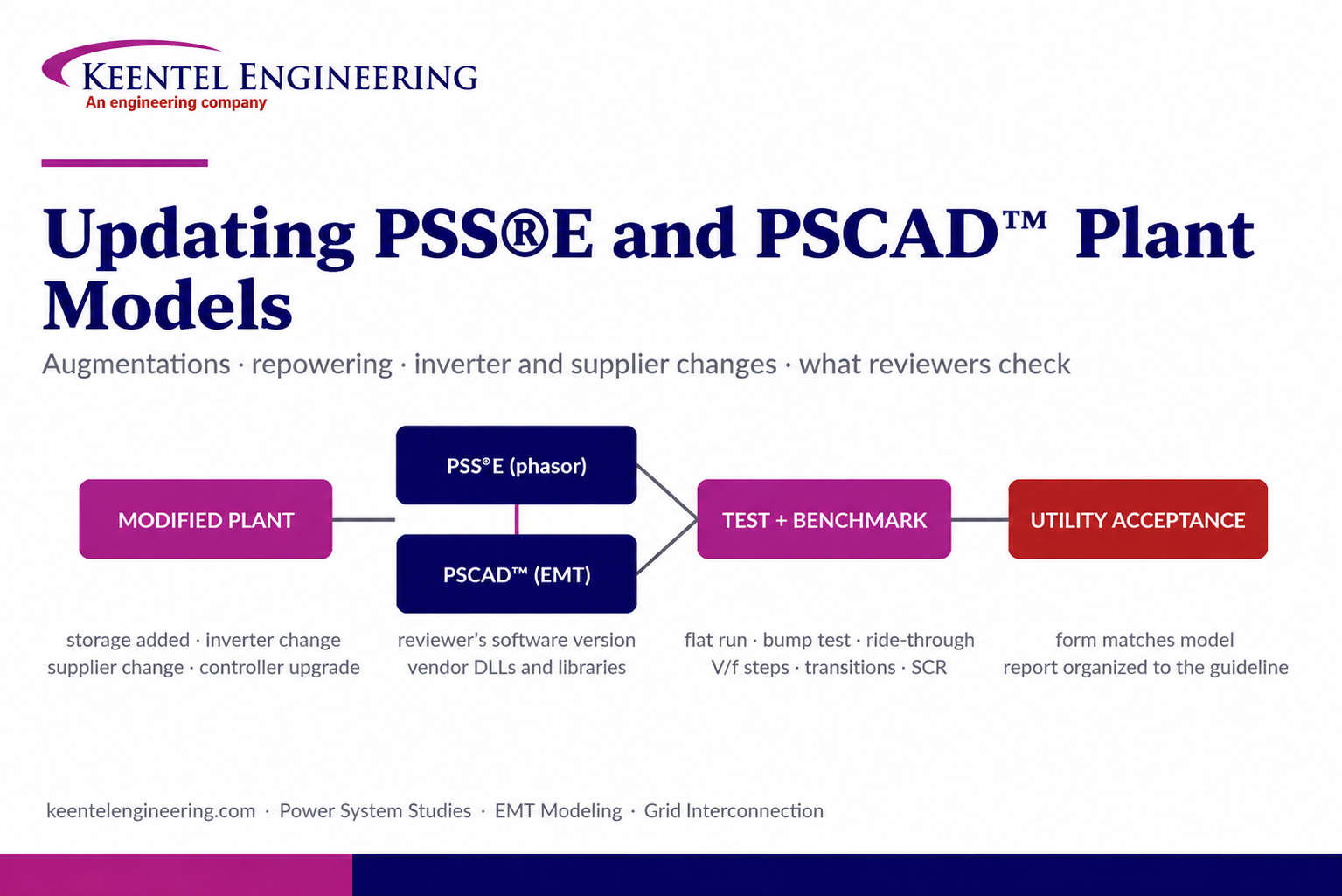
Learn how PSS®E and PSCAD™ model updates support plant augmentations, repowering, equipment changes, testing, benchmarking, and grid compliance.
By SANDIP R PATEL
•
September 20, 2026
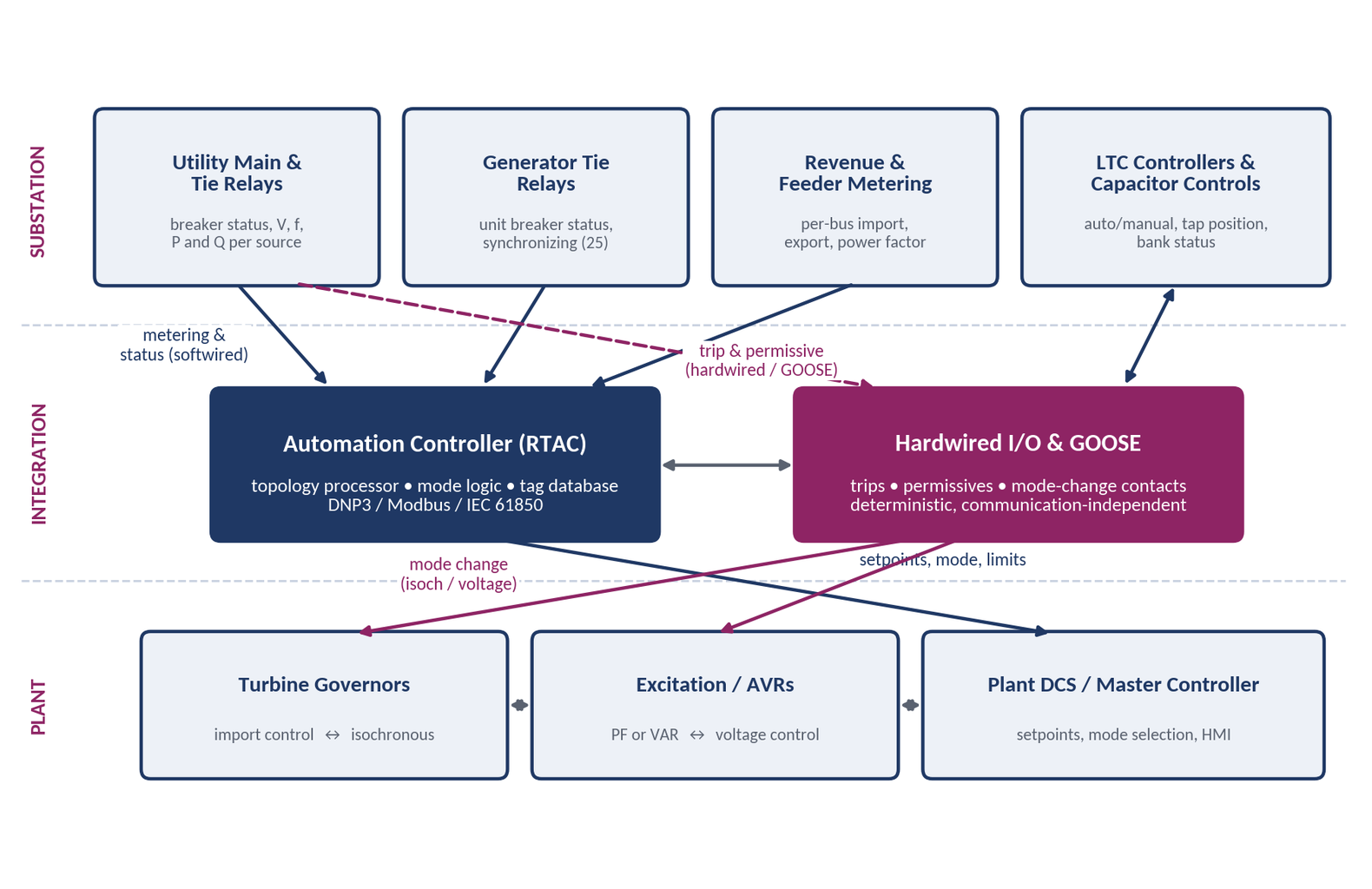
Learn CHP load following and island detection engineering for campus plants, including protection, controls, power studies, and grid transition design.





