
A Coordinated Electric System Interconnection Review—the utility’s deep-dive on technical and cost impacts of your project.
Challenge: Frequent false tripping using conventional electromechanical relays
Solution: SEL-487E integration with multi-terminal differential protection and dynamic inrush restraint
Result: 90% reduction in false trips, saving over $250,000 in downtime
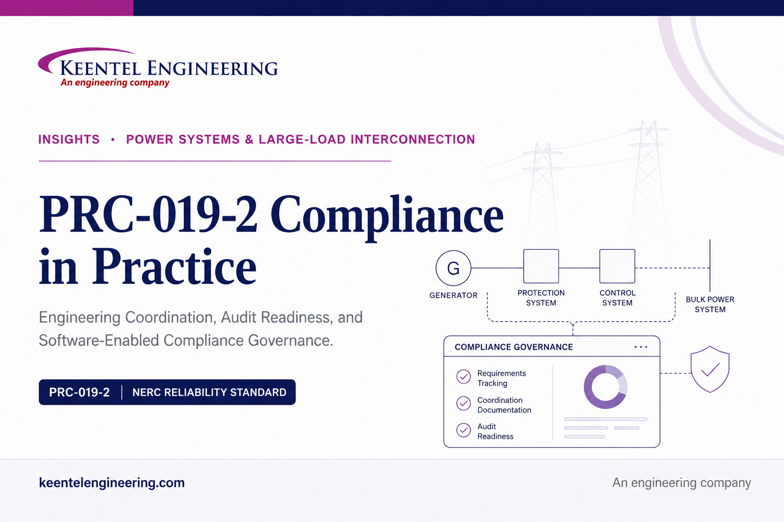
PRC-019-2 Compliance: A Technical Guide to Generator Voltage Control Coordination, Audit Readiness, and Compliance Software
Aug 12, 2026 | Blog
For Generator Owners and Transmission Owners managing synchronous generators, synchronous condensers, dispersed power producing resources, solar, wind, and battery energy storage facilities
Executive overview
NERC Reliability Standard PRC-019-2 requires Generator Owners and applicable Transmission Owners to coordinate generating unit or plant equipment capabilities, voltage regulating system controls, in-service limiters, protection functions, and applicable Protection System settings. The standard is designed to prevent two opposite reliability failures: unnecessary disconnection while the equipment is still operating within an acceptable capability region, and delayed isolation when operating conditions exceed equipment capability or stability limits.
The requirement appears concise, but the engineering and governance work behind it is substantial. A defensible PRC-019-2 program must connect facility applicability, equipment data, excitation or inverter controls, relay settings, capability curves, study assumptions, field configuration, document dates, periodic review, change management, evidence retention, and audit traceability. For synchronous machines, the program commonly includes volts-per-hertz coordination, overexcitation coordination, and underexcitation coordination on P-Q or R-X planes. For dispersed power producing resources and inverter-based resources, the RSTC/SPCWG guidance illustrates voltage coordination at the inverter, collector bus, and point of interconnection.
Requirement R1 establishes a maximum five-calendar-year interval for the coordination review. Requirement R2 requires the same coordination within 90 calendar days after the identification or implementation of a system, equipment, or setting change that affects the R1 coordination. The compliance burden is therefore both periodic and event-driven. An entity can have technically sound relay settings and still create audit exposure if it cannot prove when the analysis was performed, which settings were analyzed, what changed, who approved the determination, and whether the required interval was met.
Keentel Engineering can support this full lifecycle through NERC compliance services that combine protection and controls engineering, facility applicability review, study development, evidence package preparation, RSAW readiness, remediation planning, and software-enabled compliance governance. The goal is not to produce a single plot or a one-time audit binder. The goal is to establish a repeatable system that keeps the engineering baseline, field configuration, change records, due dates, and evidence aligned over the life of the facility.
Core compliance principle
Controls and limiters should act early enough to preserve the unit or facility when operation remains recoverable. Protection should act decisively when equipment capability or stability limits are exceeded. The evidence must show both sides of that coordination and must be dated, traceable, and repeatable.
Why PRC-019-2 Matters to Reliability, Operations, and Compliance
PRC-019-2 sits at the intersection of equipment protection and Bulk Electric System performance. A generator, synchronous condenser, or inverter-based plant can be harmed if protection does not operate when capability limits are exceeded. The same facility can create a wider reliability problem if protection operates too early and removes needed real or reactive power during a system disturbance. The standard therefore asks the owner to demonstrate an intentional operating hierarchy rather than treat each relay, limiter, controller, or OEM curve as an isolated artifact.
From an operations perspective, voltage regulating controls are expected to support terminal voltage or plant-level voltage objectives within the equipment capability envelope. Limiters constrain the control system before the equipment is driven into an unsafe region. Protection provides the next layer of defense by isolating or de-energizing equipment when the abnormal condition exceeds capability or stability boundaries. A technically strong study shows where each layer begins, what assumptions were used, and why the sequence is appropriate.
From a compliance perspective, PRC-019-2 is a documentation-intensive standard. The measure for R1 expects dated evidence that the coordination was performed. The measure for R2 expects dated evidence that the event-driven coordination was completed within the specified interval. The RSAW reinforces the need for a list of applicable voltage regulating controls, facility summaries, compliance narratives, evidence references, document revisions, dates, relevant pages, and descriptions of applicability. The audit team may review all facilities or a sample, so every facility record should be capable of standing on its own.
The standard carries a Medium Violation Risk Factor and a Long-term Planning time horizon for both requirements. Those labels should not be interpreted as a reason to defer action. The R1 deadline remains five calendar years, and the R2 deadline remains 90 calendar days. Violation Severity Level bands describe the severity of noncompliance after a missed deadline; they are not compliance grace periods.
Applicability: Determining Which Facilities Are in Scope
A reliable PRC-019-2 program begins with a controlled applicability determination. The standard applies to Generator Owners and to Transmission Owners that own synchronous condensers. The facility thresholds and special categories should be evaluated using gross nameplate ratings, Bulk Electric System connectivity, common-bus aggregation, dispersed power producing resource configuration, and blackstart designation.
| Facility category | Applicability test | Program implication |
|---|---|---|
| Individual generating unit | Greater than 20 MVA gross nameplate and directly connected to the BES | Maintain unit-specific controls, protection, capability, study, review-date, and change records |
| Individual synchronous condenser | Greater than 20 MVA gross nameplate and directly connected to the BES | Apply generator-like overflux, overexcitation, and underexcitation coordination adapted to condenser operation |
| Generating plant or facility | One or more units connected to the BES at a common bus with more than 75 MVA gross aggregate generation | Define whether coordination is performed at unit, plant, or both levels based on actual control and protection architecture |
| Dispersed power producing resources | Facilities identified through BES Inclusion I4 where voltage regulating control is performed solely at individual generating units | Evaluate the individual generating units and associated facility protection interfaces |
| Blackstart generator | Any size when material to and designated in a Transmission Operator restoration plan | Do not rely on the normal MVA threshold to exclude the unit |
Applicability errors often occur when ownership and control boundaries do not match the simplified one-line diagram. A plant may have individual inverter controls, feeder protection, a plant controller, reactive devices, and high-side protection owned or maintained by different groups. The compliance record should identify the responsible entity, applicable facility boundary, voltage regulating functions, in-service limiters, protection functions, and Protection System devices that are included in the analysis.
A strong applicability file should include the BES determination, gross nameplate data, common-bus aggregation logic, blackstart status, one-line diagram, asset ownership, control architecture, and approval by a knowledgeable subject matter expert. The file should also record why any nearby asset or function was excluded. Documented exclusions are valuable because they show that the entity considered the issue rather than simply omitted it.
Requirement R1: The Five-Year Engineering Coordination Obligation
Requirement R1 requires each applicable entity to coordinate voltage regulating system controls, including in-service limiters and protection functions, with applicable equipment capabilities and settings of applicable Protection System devices and functions at a maximum interval of every five calendar years. The verification assumes the normal automatic voltage regulator control loop and steady-state system operating conditions.
The standard then establishes two complementary tests. First, in-service limiters should be set to operate before the Protection System in order to avoid unnecessary disconnection. Second, applicable in-service Protection System devices should be set to isolate or de-energize equipment when operating conditions exceed equipment capabilities or stability limits. A complete study must therefore demonstrate both adequate operating margin and adequate protection.
What “coordination” should mean in a defensible engineering record
Coordination is more than confirming that two numerical pickups are different. It requires a common engineering basis that allows controls, limiters, protection characteristics, and equipment capabilities to be compared. That basis may include per-unit conversion, current or voltage transformer ratios, generator or plant MVA base, terminal-voltage assumptions, frequency assumptions, transformer impedance, system equivalent reactance, time-delay characteristics, control tolerances, measurement error, modeling limitations, and normal operating conditions.
The record should explain how the engineer determined that a limiter has a meaningful opportunity to act before the Protection System. For time-dependent functions, that may require comparing inverse-time characteristics and thermal capability curves. For P-Q or R-X coordination, it may require comparing the UEL, loss-of-field zones, machine capability, steady-state stability limit, and expected operating region. For inverter-based resources, it may require comparing inverter ride-through controls and trips with feeder, collector bus, and point-of-interconnection voltage protection.
Minimum engineering inputs for an R1 review
1: Controlled facility data: gross MVA ratings, one-line diagrams, transformer data, auxiliary transformer data, ownership boundaries, and normal operating configurations
2: Equipment capability data: OEM generator capability curves, field and stator thermal limits, end-region limits, generator and transformer volts-per-hertz capability, inverter current and voltage capability, and reactive device ratings
3: Control settings: AVR settings, OEL, UEL, volts-per-hertz limiter, inverter control limits, plant controller set points, reactive device controls, and relevant control logic
4: Protection settings: loss-of-field, overexcitation, volts-per-hertz, overvoltage, undervoltage, feeder protection, collector bus protection, high-side transformer protection, and other functions that define the operating boundary
5: Field configuration evidence: relay setting exports, excitation or inverter parameter files, firmware or software versions, commissioning records, and confirmation that the analyzed settings match the in-service configuration
6: Study assumptions and bases: per-unit bases, voltage and frequency assumptions, system equivalent data, stability assumptions, tolerances, and any conservative margins
7: Approval and date evidence: engineer review, independent check where required, approval date, revision number, and the next five-year due date
R1 technical deliverables by coordination domain
| Coordination domain | Technical objective | Typical evidence |
|---|---|---|
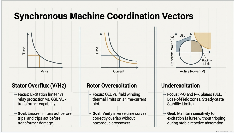
| Stator overflux or V/Hz | Show that limiter and alarm action precede relay or excitation-system protection while generator, GSU, and applicable auxiliary transformer capability are protected | Time versus V/Hz plot, OEM capability curves, limiter settings, relay settings, basis conversions, and margin explanation |
| Rotor or field overexcitation | Show that the OEL acts before protective tripping and that protection operates before field winding thermal damage | Time versus field current plot, OEL curve, excitation protection, relay curve, field thermal capability, and current-base calculations |
| Underexcitation | Show that UEL action, loss-of-field protection, machine capability, end-region limit, and stability boundary are appropriately separated | P-Q diagram, R-X diagram, UEL characteristic, LOF zones, capability curve, SSSL, and operating region |
| Synchronous condenser | Apply the same layered philosophy while accounting for condenser operation near zero real power and reactive production or absorption | Overflux and overexcitation curves plus underexcitation plot across the relevant D-curve region |
| Inverter-based or dispersed resources | Coordinate inverter ride-through and trips with feeder protection, collector bus protection and reactive controls, and POI protection or interconnection capability | Voltage-time plots at inverter, collector bus, and POI; control settings, protection settings; plant-controller logic; and vendor capability data |
Evidence quality: what makes an R1 package audit-ready
An audit-ready R1 package allows a reviewer to move from the facility inventory to the final engineering conclusion without guessing. The package should include a controlled study report, a settings and data appendix, legible plots, clear labels, units and bases, document dates, revision history, reviewer approval, and a cross-reference to the facility and protection records. Each plot should show the relevant capability boundaries and operating regions, not merely a line labeled “compliant.”
The RSAW suggests that evidence may take the form of P-Q diagrams, R-X diagrams, inverse-time diagrams, or an equivalent table. That flexibility is valuable, but equivalent evidence must still demonstrate the actual coordination. A table listing pickups without showing the relationship to capability, time, stability, and operating region may not be persuasive. The engineering narrative should explain why the selected representation is technically appropriate for the equipment and control architecture.
Important scope limitation
The standard does not require an entity to install or activate every limiter or protection function listed in Section G. It requires coordination of the applicable functions that are installed and activated. The inventory should therefore distinguish in-service functions from available but disabled functions and should document the basis for that status.
Technology-Specific Coordination for Synchronous Machines and Inverter-Based Resources
Synchronous generator stator overflux coordination
Stator overflux coordination compares the excitation system volts-per-hertz limiter and related alarms or protection with relay volts-per-hertz protection and the overexcitation capability of the generator and connected transformers. The engineering objective is to allow the control system to correct or limit the condition before a trip is required, while ensuring that prolonged or severe overfluxing is cleared before equipment damage.
The study should use consistent voltage, frequency, and time bases. Transformer and generator capability curves may not be expressed on the same base, and auxiliary transformers may have different limitations. The final plot should identify the most restrictive applicable equipment capability, the limiter curve, relay stages, excitation-system protection if present, and the expected normal operating point. Where tolerances could erode margin, the engineer should address them explicitly.
Synchronous generator overexcitation coordination
Overexcitation coordination addresses rotor or field winding heating caused by excessive field current. The normal hierarchy is field current regulation or limiting, followed by excitation-system or relay protection, with the equipment thermal capability as the ultimate boundary. Because both limiter and protection may use inverse-time behavior, the complete curve matters more than a single pickup point.
A defensible study identifies current bases, CT ratios where applicable, field-current measurement scaling, cold or hot capability assumptions, limiter timing, protection timing, and the OEM thermal capability. The engineer should verify the full range of interest, including high-magnitude short-duration conditions and lower-magnitude sustained conditions. Any crossover between a limiter and protection curve should be understood and justified.
Synchronous generator underexcitation coordination
Underexcitation coordination is frequently the most complex part of a PRC-019-2 study because it combines control, protection, thermal capability, and stability. The UEL is intended to keep the generator away from unsafe or unstable underexcited operation. Loss-of-field protection must remain sensitive to genuine excitation failures while avoiding operation during stable, permissible reactive-power absorption or during the UEL response.
The study may be developed on a P-Q plane, an R-X plane, or both. The P-Q representation is intuitive for operations because it shows real and reactive power. The R-X representation aligns directly with impedance-based loss-of-field relay zones. The record should explain the transformations, bases, machine reactances, system equivalent reactance, terminal voltage, and any steady-state stability limit calculation. The standard reference section provides equations for the steady-state stability limit using generator direct-axis synchronous reactance and the equivalent reactance to the infinite bus.
The final conclusion should not be limited to “no overlap.” The engineer should evaluate expected operating trajectories, relay time delays, voltage dependence, system strength, end-region heating, limiter tolerances, and the practical ability of the UEL to respond. Where a coordination conflict exists, the remediation may involve control settings, relay settings, operating limits, or a documented engineering justification approved through the entity’s change-control process.
Synchronous condenser coordination
A synchronous condenser has no real-power production objective, but its excitation system, field winding, stator, transformers, limiters, and protection still require coordination. The RSTC/SPCWG guidance uses overflux, overexcitation, and underexcitation examples analogous to synchronous generation. Underexcitation analysis should account for the small amount of real power absorbed from the grid to operate the machine and may be shown over the entire D-curve where that representation better communicates the operating range.
The compliance record should avoid copying a generator template without adapting the assumptions. Real-power direction, normal operating region, reactive capability, transformer configuration, auxiliary load, and protection logic may differ. The study should reflect the actual condenser controls and in-service protection.
Dispersed power producing resources and inverter-based resources
Dispersed power producing resources differ fundamentally from synchronous machines because they do not use a conventional excitation system. The RSTC/SPCWG guidance therefore illustrates a layered voltage-coordination approach rather than a generator capability and excitation-limiter approach. The three example levels are the inverter, collector bus, and point of interconnection.
1: Inverter voltage coordination: compare inverter low-voltage and high-voltage ride-through or trip characteristics with feeder protection and internal controls so the inverter does not disconnect unnecessarily for disturbances that should be cleared or ridden through
2: Collector bus voltage coordination: compare collector-bus voltage protection with capacitor-bank controls, SVCs, STATCOMs, plant-controller logic, and the voltage capability of collection-system equipment
3: Point-of-interconnection voltage coordination: compare high-side main-transformer or POI protection with interconnection voltage capability, transmission-system expectations, and plant-level control behavior
For modern solar, wind, and battery facilities the study team should also manage vendor parameter files, inverter model or firmware versions, plant-controller modes, reactive-priority logic, current limiting, active-power recovery behavior, and the relationship between local inverter trips and plant-level protection. PRC-019-2 does not replace other applicable ride-through or modeling standards, but the coordination evidence should be internally consistent with the facility’s actual operating strategy and protection architecture.
A recurring risk is that the plant controller, inverter settings, feeder relays, collector-bus relays, and POI relays are maintained by different parties. Keentel Engineering’s integrated review approach can create one controlled coordination baseline that identifies the owner and revision of every input, highlights gaps, and assigns actions across the relevant engineering disciplines.
Requirement R2: Change-Triggered Coordination Within 90 Calendar Days
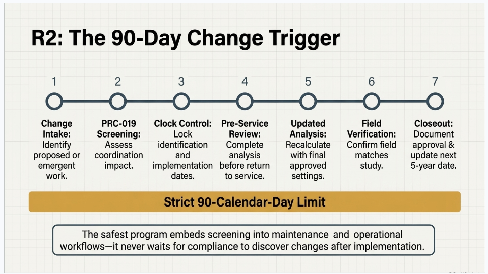
Requirement R2 applies when an entity identifies or implements a system, equipment, or setting change that affects the coordination required by R1. The entity must perform the R1 coordination within 90 calendar days. The standard lists voltage-regulating settings or equipment changes, Protection System settings or component changes, equipment capability changes, and generator or synchronous-condenser step-up transformer changes as examples, but the list is not exclusive.
R2 is best understood as an engineering configuration-management requirement. The compliance risk is not limited to major capital projects. A relay setting revision, excitation-system parameter change, firmware update, control-logic change, CT or VT replacement, transformer replacement, uprate, revised capability curve, plant-controller tuning change, reactive-device change, or protection-function enablement can affect the coordination. The entity needs a formal screening process that captures both planned and emergent work.
A defensible R2 workflow
1: Change intake: capture the proposed or discovered change with the facility, equipment, affected settings, reason, owner, planned implementation date, and supporting documents
2: PRC-019 screening: determine whether the change can alter a control characteristic, limiter, protection function, equipment capability, stability assumption, transformer characteristic, measurement basis, or study conclusion
3: Clock control: record both the identification date and implementation date, assign a responsible owner, and apply a conservative due-date rule so the 90-calendar-day interval is not missed
4: Pre-service engineering review: for changes with clear coordination impact, complete or substantially complete the engineering review before returning the equipment to service when practicable; the RSTC/SPCWG guidance specifically recommends this approach for changes such as excitation-system or generator-relay replacement
5: Updated analysis: recalculate affected plots or tables using the final approved settings and equipment data, not preliminary values
6: Independent verification: confirm that the implemented field configuration matches the studied configuration and that all affected layers were considered
7: Approval and closeout: document the conclusion, approval date, evidence references, implementation confirmation, and whether the five-year baseline or next review date changes under the entity’s program
Impact determinations and “no change to coordination” decisions
Not every maintenance action requires a full new study, but every credible trigger should be screened. A “no impact” determination should identify the change, describe the affected function, explain why the existing coordination remains valid, reference the current study and settings, and include qualified engineering approval. A one-line statement that a change is “administrative” is weak if the underlying firmware, scaling, curve, control logic, or relay element behavior changed.
The screening process should distinguish document-only changes from functional changes. It should also identify situations where an apparently unrelated change affects the common engineering basis. For example, a CT ratio change may not alter the relay’s displayed secondary setting but can alter the primary operating characteristic. A transformer replacement can change V/Hz capability, impedance, or the system equivalent used in underexcitation analysis. A plant-controller update can change voltage control priority even when individual inverter trip thresholds remain unchanged.
R2 evidence that survives audit sampling
| Evidence item | Purpose | Audit-ready content |
|---|---|---|
| Change register | Defines the audit population | All relevant changes, dates, facility, equipment, owner, screening result, and linked work order or engineering change notice |
| Impact assessment | Shows why R2 did or did not apply | Technical rationale, affected coordination domains, reviewer, approval, and references to settings or capability data |
| Updated study | Demonstrates R1 coordination after the change | Revised plots or tables, calculations, final settings, date, revision, and conclusions |
| Implementation confirmation | Links the study to the field | As-left relay or control settings, commissioning test, settings checksum or export, firmware version, and return-to-service date |
| Timeline record | Demonstrates the 90-day interval | Identification date, implementation date, study completion date, approval date, and due-date calculation |
R2 control principle
The safest program does not wait for the compliance department to discover changes after implementation. PRC-019 screening should be embedded in protection, controls, maintenance, procurement, commissioning, and management-of-change workflows.
Audit Readiness: How the RSAW Shapes Evidence Expectations
The PRC-019-2 Reliability Standard Audit Worksheet is a reference document that describes part of the methodology NERC and Regional Entities may use to assess compliance. It is not a substitute for the standard, does not create additional enforceable requirements, and does not guarantee compliance when an entity follows its examples. Nevertheless, it is an important audit-preparation tool because it reveals the structure of likely evidence requests and auditor review.
For R1, the RSAW asks whether the entity has applicable facilities, requests a summary of those facilities, requires a compliance narrative, and suggests a list of all applicable voltage regulating system controls. It then requests dated coordination evidence for all or sampled facilities and identifies P-Q diagrams, R-X diagrams, inverse-time diagrams, or equivalent evidence as possible forms. The auditor assessment approach focuses on whether limiters operate before protection and whether protection isolates equipment when capability or stability limits are exceeded.
For R2, the RSAW asks whether the entity identified or implemented changes during the audit period that affected R1 coordination. It requests a list of changes, dated evidence of the updated coordination, and proof that the 90-calendar-day interval was met. This structure means the audit team may begin with the change population rather than with the studies. If the change register is incomplete, the entity may be unable to demonstrate that the audit population itself is complete.
What auditors are likely to test
1: Completeness: whether all applicable facilities, controls, limiters, protection functions, and qualifying changes are included
2: Technical validity: whether the study uses correct equipment data, settings, bases, assumptions, and capability or stability boundaries
3: Timing: whether the five-year and 90-day requirements were met using dated evidence
4: Configuration alignment: whether the studied settings and firmware match the in-service equipment
5: Traceability: whether each conclusion can be traced to a controlled document, revision, page, plot, setting file, and approval
6: Process execution: whether the written procedure is actually followed across engineering, maintenance, operations, and compliance
Evidence-index design for fast audit response
The RSAW asks entities to identify file name, document title, revision or version, document date, relevant pages or sections, and a description of document applicability. Keentel Engineering recommends building the evidence index before the audit rather than assembling it reactively. Every item should have a unique identifier and a direct link to the controlled source. Study plots should be bookmarked, and the evidence narrative should identify the exact page where each R1 or R2 assertion is demonstrated.
The standard requires the Generator Owner and Transmission Owner to retain evidence of compliance with R1, R2, M1, and M2 for six years. If noncompliance is identified, related evidence must be retained until mitigation is complete and approved or for the normal period, whichever is longer. A software-enabled retention rule can prevent accidental deletion while also avoiding uncontrolled duplicate files.
Common PRC-019-2 Failure Patterns and Control Weaknesses
The highest-risk PRC-019-2 weaknesses are usually not isolated mathematical errors. They are breaks in the chain between scope, data, engineering, implementation, change control, and evidence. The following patterns should be treated as leading indicators of audit exposure.
1: Incomplete applicability inventory: a blackstart unit, synchronous condenser, aggregate plant, dispersed unit, or newly registered facility is absent from the program
2: Relay-only study: the package includes relay settings but omits in-service limiters, control behavior, capability curves, or stability limits
3: Uncontrolled equipment data: OEM curves are undated, scanned without provenance, based on a different rating, or inconsistent with the current transformer or equipment configuration
4: Field-to-study mismatch: the relay export, AVR settings, inverter firmware, or plant-controller revision in service does not match the version analyzed
5: Overexcitation gap: the OEL, excitation protection, relay curve, and field thermal capability are not shown on a common basis across the relevant time range
6: Underexcitation gap: the UEL and loss-of-field zones are plotted without a credible machine capability, end-region limit, SSSL, or operating region
7: IBR coordination gap: the facility relies on vendor ride-through settings but does not coordinate inverter, feeder, collector-bus, reactive-device, and POI protection
8: Five-year tracking weakness: due dates are maintained in personal calendars or spreadsheets without escalation, ownership, or evidence linkage
9: R2 trigger weakness: engineering and maintenance changes are not screened consistently, and compliance learns about them after the 90-day interval
10: Weak no-impact determination: a change is closed as non-impacting without technical rationale or qualified approval
11: Undated or ambiguous evidence: the study exists, but the entity cannot prove when coordination was completed or which revision was approved
12: RSAW narrative without evidence mapping:
the narrative repeats the requirement but does not explain the entity’s actual process or point to exact evidence
How Keentel Engineering Supports PRC-019-2 Compliance
Keentel Engineering can help Generator Owners and applicable Transmission Owners establish or strengthen a complete PRC-019-2 program. The service model can be scaled from a targeted engineering review for one facility to a portfolio-wide compliance transformation that includes technical studies, governance, software workflows, and audit preparation.
| Service area | Keentel Engineering support | Client value |
|---|---|---|
| Applicability and inventory | Facility screening, BES and threshold documentation, controls and protection inventory, ownership mapping, and gap identification | A controlled population for R1, R2, and audit sampling |
| Engineering studies | V/Hz, overexcitation, underexcitation, P-Q, R-X, inverse-time, synchronous-condenser, inverter, collector-bus, and POI coordination | Technically defensible evidence aligned to actual equipment and settings |
| Data validation | Review of OEM capability, relay exports, AVR or inverter parameters, transformer data, firmware, and as-left configuration | Reduced risk of study-to-field mismatch |
| R2 change management | Trigger criteria, intake forms, impact assessments, due-date controls, pre-service review gates, and closeout records | Reliable identification and completion of event-driven coordination |
| Audit readiness | RSAW narrative support, evidence index, sampling preparation, mock interviews, gap closure, and response packages | Faster, clearer, and more consistent audit response |
| Compliance software | Asset registry, requirement mapping, due dates, change workflows, approvals, evidence repository, dashboards, and audit package generation | Sustainable compliance beyond a one-time study |
A practical Keentel Engineering delivery model
1: Phase 1 - Scope and readiness: confirm applicability, identify facilities and owners, inventory controls and protection, review existing evidence, and prioritize gaps
2: Phase 2 - Data and configuration validation: collect controlled equipment data, obtain as-left settings, resolve base and revision conflicts, and document assumptions
3: Phase 3 - Technical coordination: develop or update required plots and calculations, evaluate margins, identify conflicts, and prepare engineering recommendations
4: Phase 4 - Remediation and implementation support: support approved setting or control changes, verify final configuration, and update the compliance baseline
5: Phase 5 - Audit-ready evidence: assemble the dated report, evidence matrix, approvals, page references, R1 narrative, and R2 records
6: Phase 6 - Sustainable governance: configure software workflows, review schedules, change triggers, evidence retention, dashboards, and periodic quality checks
This delivery model is intentionally cross-functional. PRC-019-2 cannot be sustained by the compliance team alone. Keentel Engineering can facilitate the technical handoffs among plant engineering, protection, controls, operations, maintenance, asset management, IT or operational technology, and compliance personnel so that the same approved configuration is reflected in the study, field, and evidence repository.
NERC Compliance Software for Sustainable PRC-019-2 Governance
NERC compliance software should do more than store PDF files. For PRC-019-2, the software needs to maintain relationships among facilities, equipment, controls, limiters, protection functions, studies, settings revisions, changes, deadlines, approvals, and evidence. Keentel Engineering can help design, configure, or support a software-enabled control environment around those relationships.
Recommended software capabilities
1: Facility and asset registry: a controlled list of applicable facilities with ownership, ratings, BES basis, blackstart status, control architecture, protection devices, and accountable SMEs
2: Requirement mapping: direct mapping of R1 and R2 obligations, measures, evidence types, retention rules, and internal controls to each applicable facility
3: Five-year due-date engine: automated calculation of next review dates, reminder escalation, management visibility, and evidence of timely completion
4: R2 change intake and screening: workflow forms that capture identification and implementation dates, affected equipment, change type, screening questions, engineering determination, and 90-day due date
5: Configuration and revision control: links to relay exports, AVR files, inverter parameters, firmware, capability data, studies, and as-left verification
6: Approval workflow: qualified preparer, independent reviewer, compliance review, owner approval, electronic date stamp, and controlled closeout
7: Evidence repository: single-source storage with required metadata, page references, document versions, bookmarks, retention status, and audit-package tagging
8: Dashboards and exceptions: open R2 actions, studies due within defined windows, overdue approvals, incomplete inventories, and field-to-study mismatches
9: Audit package builder: export of facility lists, narratives, evidence indexes, change populations, timing calculations, and linked supporting documents
10: Management reporting: portfolio-level status, risk trends, upcoming obligations, remediation progress, and recurring root causes
How software reduces PRC-019-2 risk
Software creates value when it enforces the process rather than merely recording the result. A change request can require PRC-019 screening before approval. A setting file cannot be closed without the final as-left attachment. A facility record can show that the current study references an obsolete firmware revision. A dashboard can escalate an R2 action before the 90-day deadline. An audit package can be generated from controlled metadata instead of reconstructed from email and shared drives.
Keentel Engineering’s compliance software services can include requirements configuration, workflow design, evidence taxonomy, legacy data migration, role and permission mapping, dashboard definition, user acceptance testing, procedure alignment, training, and ongoing quality review. This combination of technical engineering and compliance-system design is particularly valuable for PRC-019-2 because the software must understand the meaning of the engineering records it is governing.
Software design principle
The best PRC-019-2 system connects every compliance conclusion to the current facility, current configuration, current study, responsible engineer, required due date, and exact evidence location.
Three Anonymized Composite Case Studies
Case study notice
The following case studies are anonymized composite scenarios based on common industry conditions and the technical expectations reflected in the supplied PRC-019-2 documents. They do not identify any client, facility, or project and should not be read as claims about a specific engagement.
Case Study 1: Closing Synchronous Generator Coordination Gaps Before the Five-Year Deadline
| Facility profile | A conventional BES-connected synchronous generating unit with a static excitation system, digital generator protection, a generator step-up transformer, and an auxiliary transformer |
| Primary requirement | R1 periodic coordination, with R2 screening for settings changes identified during the review |
| Primary risk | The existing package contained relay settings and an old capability curve but did not demonstrate complete limiter-to-protection-to-capability coordination |
| Keentel focus | Data validation, V/Hz, overexcitation, underexcitation, configuration reconciliation, evidence indexing, and change-control integration |
Situation
The owner had a legacy PRC-019 study that was approaching the five-year maximum interval. The document included a generator capability curve and loss-of-field relay zones, but the source of the curve was unclear, the UEL revision was not identified, and the R-X conversion did not match the present relay setting file. The V/Hz section showed the generator curve but did not include the step-up transformer or auxiliary transformer capability. The overexcitation section listed an OEL pickup and relay pickup without showing inverse-time characteristics or field winding thermal capability.
A preliminary evidence review also found that an excitation-system maintenance activity had changed a parameter several years earlier. The maintenance record did not state whether the change affected PRC-019 coordination. This created both an R1 technical gap and a potential R2 governance question.
Keentel Engineering approach
1: Scope confirmation: verified the unit’s applicability, equipment boundary, in-service control and protection functions, and accountable engineering owners
2: Configuration reconciliation: compared relay exports, excitation-system settings, one-line diagrams, CT and VT ratios, transformer data, and prior study revisions to identify the true as-left configuration
3: Capability-data validation: obtained or reconstructed controlled generator, field, stator, end-region, GSU, and auxiliary-transformer capability data with documented sources and bases
4: V/Hz coordination: placed limiter, excitation protection, relay stages, alarms, and all applicable equipment capability curves on a common voltage-frequency-time basis
5: Overexcitation coordination: developed a time-versus-field-current plot showing OEL action, excitation protection, relay behavior, and field thermal capability across the relevant range
6: Underexcitation coordination: updated P-Q and R-X plots with the current UEL, loss-of-field zones, generator capability, end-region boundary, and steady-state stability limit
7: R2 screening: documented the prior excitation parameter change, evaluated its effect, and linked the determination to the current study rather than leaving the question unresolved
8: Evidence package: created a dated report, revision history, assumptions appendix, settings index, approval record, RSAW cross-reference, and next-review tracking record
Illustrative findings
The composite analysis identified that the technical conclusion could not be supported by the original evidence because the equipment capabilities and settings were not on a consistent basis. The updated study showed acceptable coordination in several regions but identified a narrow underexcitation margin that required an engineering decision. Rather than make an undocumented adjustment, the owner’s protection and controls teams reviewed operating needs, relay sensitivity, UEL response, and stability assumptions through the formal change process.
The V/Hz review also showed that transformer capability, not generator capability, governed part of the time range. Including that curve changed the protection rationale and strengthened the evidence that the selected stages protected all applicable equipment.
Illustrative outcome
The facility obtained a complete R1 package that connected current settings to equipment capability and documented every basis conversion. The owner also established a repeatable R2 screening gate for excitation and relay work. The primary value was not a single plot; it was the removal of uncertainty about configuration, data provenance, engineering margin, and evidence timing.
For Keentel Engineering clients, this type of engagement can be delivered as a focused gap closure or as the first facility in a standardized fleet methodology. The final deliverables can be structured for direct use in the entity’s evidence repository and RSAW response.
Case Study 2: Coordinating Inverter, Collector Bus, and POI Voltage Protection After a Controls Update
| Facility profile | A BES-connected inverter-based generating facility with multiple inverter feeders, a collector system, a dynamic reactive device, a plant controller, and high-side transformer protection |
| Primary requirement | R2 change-triggered coordination supported by R1-equivalent technical evidence |
| Primary risk | Vendor firmware and plant-controller changes were implemented through separate work streams, while protection settings remained in a different document-control system |
| Keentel focus | Change screening, voltage-time coordination at three facility levels, vendor-setting reconciliation, and software workflow integration |
Situation
The facility implemented an inverter firmware update intended to improve fault ride-through and a plant-controller tuning update intended to improve voltage response at the point of interconnection. The changes were managed by different vendors. The feeder relays, collector-bus relays, dynamic reactive device, and high-side transformer relays were maintained by the owner. No single record evaluated the combined effect on PRC-019 coordination.
The existing compliance package relied on generic vendor ride-through curves. It did not identify the firmware revision, actual parameter set, measurement location, feeder relay time delay, collector-bus voltage stages, reactive-device control response, or POI protection settings. The owner needed to determine whether R2 was triggered, establish the 90-day timeline, and produce facility-specific evidence.
Keentel Engineering approach
1: Change chronology: established the identification, approval, implementation, commissioning, and return-to-service dates for the firmware and plant-controller updates
2: Parameter inventory: collected inverter ride-through and trip parameters, firmware versions, plant-controller logic, feeder settings, collector-bus protection, reactive-device controls, and POI settings
3: Measurement mapping: documented where each voltage was measured and converted settings to consistent bases across inverter terminals, collector voltage levels, and the high side of the main transformer
4: Inverter coordination plot: compared low- and high-voltage ride-through or trip behavior with feeder protection and internal inverter limits
5: Collector-bus coordination plot: compared bus protection with plant-controller actions, capacitor or reactive-device controls, and collection-system capability
6: POI coordination plot: compared high-side protection with plant-level voltage control and interconnection capability
7: Scenario review: evaluated credible voltage trajectories, control delays, trip logic, and the possibility that one layer could disconnect equipment before another layer had time to respond
8: Software workflow: configured a change record linking the vendor releases, impact assessment, 90-day due date, study revision, approvals, and as-left parameter files
Illustrative findings
The composite review found that individual settings appeared reasonable when viewed separately, but the collector-bus protection delay and plant-controller response were not documented on the same time basis. A high-voltage action in the plant controller was also close to a protection threshold after conversion to the correct measurement location. The facility needed an integrated engineering decision rather than independent vendor assurances.
The updated evidence clarified which controls were intended to regulate voltage, which functions were intended to limit equipment, and which protection stages were intended to trip. The owner could then approve coordinated changes through normal protection and controls governance and verify the final parameter files after implementation.
Illustrative outcome
The facility closed the R2 record with a complete date chain, facility-specific plots at the inverter, collector, and POI levels, controlled settings files, and a signed technical conclusion. The software workflow preserved the relationship between the firmware update and every affected evidence item, making future reviews and audits materially easier.
For Keentel Engineering, this type of work demonstrates the value of combining inverter-based-resource engineering with NERC compliance process design. A technically correct study is necessary, but a sustainable program also needs vendor-change intake, parameter version control, due-date escalation, and evidence traceability.
Case Study 3: Building a Fleet-Wide PRC-019-2 Program With Compliance Software
| Facility profile | A mixed portfolio of conventional generating units and inverter-based facilities managed by multiple operating teams |
| Primary requirement | R1 five-year scheduling, R2 change management, evidence retention, and audit readiness across the portfolio |
| Primary risk | Facility lists, studies, settings, due dates, and change records were maintained in disconnected spreadsheets, shared drives, email, and local engineering folders |
| Keentel focus | Program governance, evidence taxonomy, software configuration, migration, dashboards, and risk-based technical review |
Situation
The owner could produce studies for most facilities, but there was no single authoritative inventory showing which units were applicable, which controls and protection functions were in service, when each R1 study was approved, which changes had occurred, or whether those changes were screened under R2. Different groups used different naming conventions. Some studies referenced relay files that had been superseded, and several change records did not identify the exact facility or equipment revision.
The compliance team spent significant effort before each assessment requesting files and reconciling dates. Engineering personnel could answer technical questions, but the answers were not consistently preserved as controlled evidence. The organization needed a program that was sustainable during personnel changes, acquisitions, equipment upgrades, and expanding inverter-based-resource ownership.
Keentel Engineering approach
1: Program architecture: defined the facility, equipment, control, limiter, protection, study, change, approval, evidence, and retention data relationships needed for PRC-019-2
2: Applicability cleanup: normalized facility names, ratings, common-bus relationships, blackstart status, ownership, and accountable SMEs
3: Evidence taxonomy: standardized document types, required metadata, revision fields, exact page references, and status values for controlled evidence
4: Five-year workflow: configured due-date calculation, staged reminders, escalation, preparer and reviewer tasks, approval, and automatic next-review scheduling
5: R2 workflow: configured change intake, technical screening, 90-day calculation, pre-service hold points, impact determination, study update, as-left verification, and closure
6: Data migration: linked current studies, settings, capability records, approvals, and prior changes to the correct facilities and flagged unresolved mismatches
7: Risk-based engineering review: prioritized facilities with overdue studies, unclear settings, IBR evidence gaps, transformer changes, or incomplete underexcitation analysis
8: Audit package design: generated facility lists, narratives, evidence indexes, change populations, due-date records, and linked documents in a repeatable format
9: Training and governance: defined roles, procedures, quality checks, management dashboards, and periodic reviews to keep the system current
Illustrative findings
The composite implementation showed that the largest risk was not the absence of documents but the absence of controlled relationships among documents. A technically current relay export was not necessarily linked to the current study. A study date did not necessarily represent the final engineering approval. A work order did not necessarily indicate whether R2 screening occurred. The software data model converted those disconnected facts into a traceable compliance record.
The portfolio view also revealed recurring technical themes, including inconsistent V/Hz capability sources, incomplete IBR collector-bus coordination, and uneven no-impact determinations. Those trends allowed the owner to direct engineering resources to systemic risks rather than respond only to the next audit sample.
Illustrative outcome
The owner established a single controlled PRC-019-2 program with visible R1 due dates, active R2 actions, evidence completeness, responsible SMEs, and unresolved technical exceptions. Audit preparation shifted from document discovery to validation of an already organized evidence set. Engineering personnel gained a reliable baseline for future settings and equipment changes.
Keentel Engineering’s role in this type of program can include both the technical content and the compliance software configuration. That combination helps ensure that the workflow asks the right engineering questions, requires the right evidence, and produces records that are useful to both subject matter experts and auditors.
Conclusion and Call to Action
PRC-019-2 is a concise standard with a broad operational footprint. It requires more than periodic relay review. It requires the owner to understand how voltage controls, limiters, protection, equipment capability, stability limits, and facility configuration interact; to prove that interaction at least every five calendar years; and to repeat the analysis within 90 calendar days when an impactful change is identified or implemented.
For synchronous generators and condensers, the technical core commonly includes V/Hz, overexcitation, and underexcitation coordination. For dispersed and inverter-based resources, the evidence should address voltage control and protection at the inverter, collector bus, and point of interconnection. Across all technologies, the program must preserve dated evidence, current settings, approvals, change records, and audit-ready traceability.
Keentel Engineering provides NERC compliance services that connect the engineering analysis to the compliance process. Support can include applicability review, technical coordination studies, settings and capability validation, R1 and R2 evidence packages, RSAW readiness, change-management design, audit support, remediation, and NERC compliance software implementation or optimization.
Recommended next step
Schedule a PRC-019-2 readiness review with Keentel Engineering to evaluate facility applicability, study age, controls and protection inventory, R2 change capture, field-to-study configuration alignment, evidence quality, and compliance software workflow maturity.
Technical FAQ
Fifty detailed questions and answers for engineering, compliance, audit, field implementation, event assessment, and NERC compliance software teams

About the Author:
Sandip "Sonny" R. Patel, P.E.
IEEE Senior Member · Founder & CEO, Keentel Engineering
In 1995, Sonny Patel earned his Electrical Engineering degree from the University of Illinois. But degrees don't build legacies — action does.
For three decades, he has worked the power industry from every side of the table: 16 years as a utility engineer at Exelon/Commonwealth Edison; generation leadership across hydroelectric, industrial steam turbine, and a 9 GW renewable fleet; NERC Regional Entity Senior Compliance Engineer and Audit Team Lead, auditing some of the nation's largest utilities; and testing and commissioning lead on equipment up to 765 kV — the very top of the North American grid.Utility. Generator. Regulator. Consultant. Few engineers have seen all four seats. Fewer still have sat in them.
His experience spans nuclear, hydro, conventional generation, renewables, oil and gas, mining — and today's data centers, where he is authoring a three-book series on data center design. He is a Licensed Professional Engineer in six states and a Licensed Electrical Contractor in Florida (Unlimited EC) — he doesn't just design the work; he's qualified to stand behind its execution.Today, as Founder and CEO of Keentel Engineering, Sonny leads a nationwide team of engineers delivering substation design, power system studies, NERC compliance, and commissioning — done right, coast to coast.Three decades. Every side of the table. One standard: accountable engineering.
Services

Let's Discuss Your Project
Let's book a call to discuss your electrical engineering project that we can help you with.
About the Author:
Sandip "Sonny" R. Patel, P.E.
IEEE Senior Member · Founder & CEO, Keentel Engineering
In 1995, Sonny Patel earned his Electrical Engineering degree from the University of Illinois. But degrees don't build legacies — action does.
For three decades, he has worked the power industry from every side of the table: 16 years as a utility engineer at Exelon/Commonwealth Edison; generation leadership across hydroelectric, industrial steam turbine, and a 9 GW renewable fleet; NERC Regional Entity Senior Compliance Engineer and Audit Team Lead, auditing some of the nation's largest utilities; and testing and commissioning lead on equipment up to 765 kV — the very top of the North American grid.
Utility. Generator. Regulator. Consultant. Few engineers have seen all four seats. Fewer still have sat in them.
His experience spans nuclear, hydro, conventional generation, renewables, oil and gas, mining — and today's data centers, where he is authoring a three-book series on data center design. He is a Licensed Professional Engineer in six states and a Licensed Electrical Contractor in Florida (Unlimited EC) — he doesn't just design the work; he's qualified to stand behind its execution.
Today, as Founder and CEO of Keentel Engineering, Sonny leads a nationwide team of engineers delivering substation design, power system studies, NERC compliance, and commissioning — done right, coast to coast.Three decades. Every side of the table. One standard: accountable engineering.
Leave a Comment
Thank you for contacting us.
We will get back to you as soon as possible.
We will get back to you as soon as possible.
Oops, there was an error sending your message.
Please try again later.
Please try again later.
Related Posts

By SANDIP R PATEL
•
September 26, 2026
Learn how to prepare a MISO large-load interconnection package, including PSS®E models, BESS smoothing, harmonic data and transmission-owner requirements.

By SANDIP R PATEL
•
September 26, 2026
Learn where storage belongs in an 800 VDC AI data center, including capacitors, flywheels, BESS, fault current, protection, grounding, and EMT design.

By SANDIP R PATEL
•
September 26, 2026
Learn how SPP’s HILL and HILLGA framework works for large-load projects, including studies, BTM generation, modeling, EMT requirements, and firm service.

By SANDIP R PATEL
•
September 25, 2026
Learn how IBR time synchronization, IEEE 2800, IRIG-B verification, and PTP solutions help meet disturbance monitoring compliance requirements.

By SANDIP R PATEL
•
September 24, 2026
Learn why continuing technical training matters in power engineering, including standards, software skills, PDH requirements, and career growth.
By SANDIP R PATEL
•
September 22, 2026
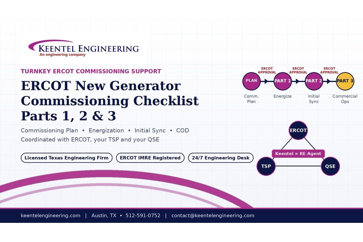
2026 ERCOT commissioning guide covering the Commissioning Plan, Checklist Parts 1–3, BESS requirements, TSP/QSE coordination, field testing and COD.

By SANDIP R PATEL
•
September 22, 2026
Learn PRC-030-1 R1 event detection requirements for inverter-based resources, SEL platforms, disturbance monitoring, and audit-ready compliance.
By SANDIP R PATEL
•
September 22, 2026
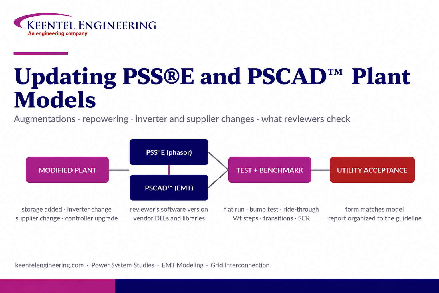
Learn how PSS®E and PSCAD™ model updates support plant augmentations, repowering, equipment changes, testing, benchmarking, and grid compliance.
By SANDIP R PATEL
•
September 20, 2026
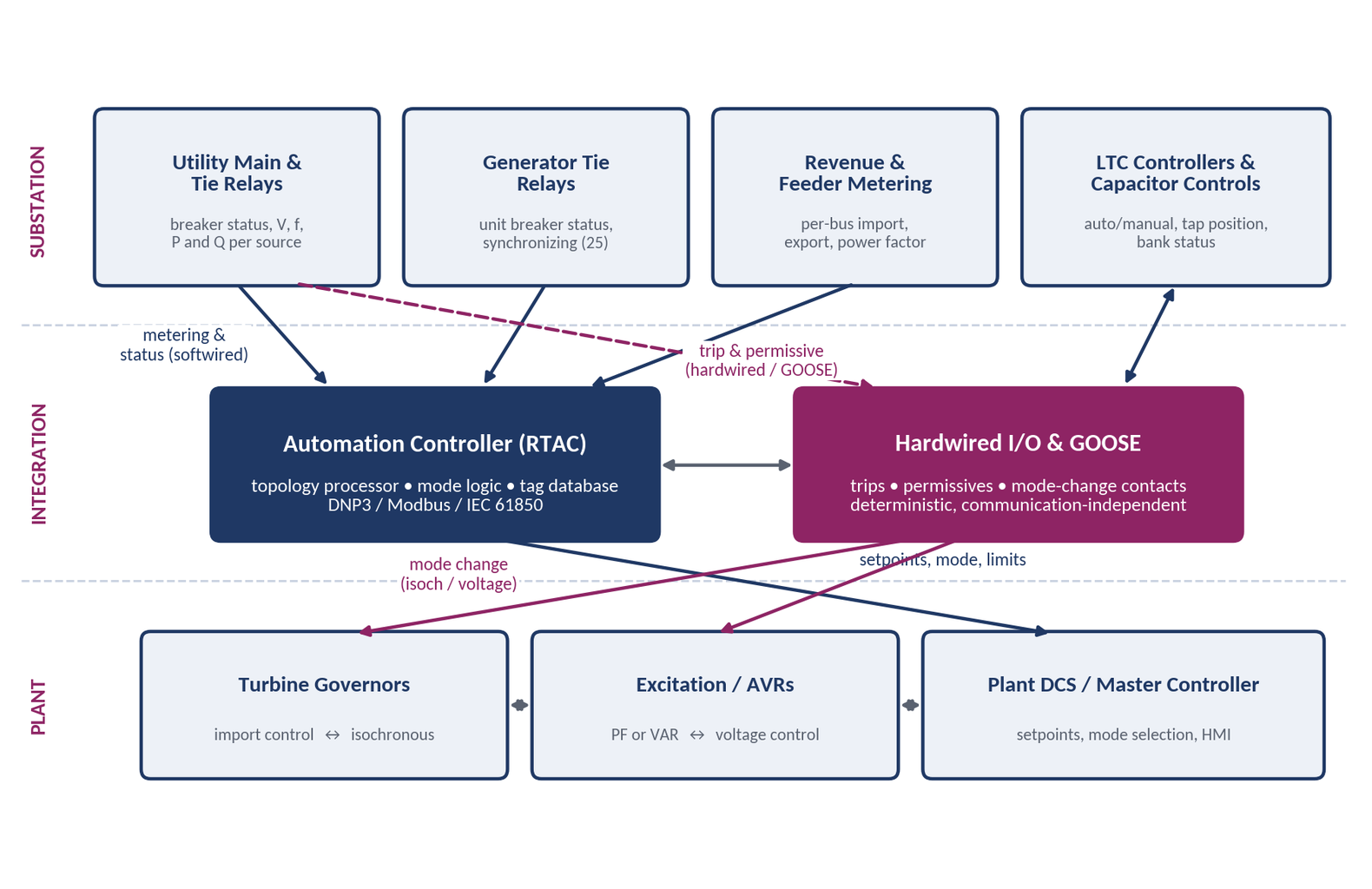
Learn CHP load following and island detection engineering for campus plants, including protection, controls, power studies, and grid transition design.





