
A Coordinated Electric System Interconnection Review—the utility’s deep-dive on technical and cost impacts of your project.
Challenge: Frequent false tripping using conventional electromechanical relays
Solution: SEL-487E integration with multi-terminal differential protection and dynamic inrush restraint
Result: 90% reduction in false trips, saving over $250,000 in downtime
ERCOT enforces all of the above through simulation, which means your model is your compliance case. The bar is now high:
- Whole-facility scope. The model must represent everything the IT load, the UPS and power conversion, the cooling plant, the protection and control systems in formats compatible with ERCOT's study platforms (PSS/E, PSCAD, TSAT).
- Real control loops, not approximations. Generic textbook representations are unacceptable. The model must capture the actual inner control behavior of your power electronics.
- Hardware-validated converter models. For electronic loads, the PSCAD model must be benchmarked against actual hardware testing including voltage ride-through and subsynchronous response. A model assembled from standard PSCAD library blocks fails by definition, because a generic block has never been tested against your vendor's hardware. The good news: validation is a hardware-type test, so results for a given converter product are reusable across every facility that uses it.
- Format migration. Facilities that previously submitted the older composite load model (CMLD) format must transition to EPRI's PERC1 format.
- Three checkpoints. Models are reviewed before the stability study begins (no model, no study), before each quarterly stability assessment, and for electronic loads one final time before energization, when you must submit as-built models with a documented comparison against the previously studied data and a sworn attestation that the model matches actual field settings. ERCOT's review takes 10 business days, extendable by 20 put it on your critical path.
- A living obligation. Change your technology, controls, or relay settings in a way that affects ride-through including converting a crypto mining site to an AI data center — and you've triggered a new interconnection study, even if your megawatts don't change.
| Parameter | Detail |
|---|---|
| System | 230 kV / 138 kV transmission corridors, wind and wet-snow icing exposure |
| Data basis | 15 years of minute-resolution forced-outage records + regional weather observations |
| Core methods | Event grouping, MVA performance curves, time-to-95%-restore, area outage rate curves, fragility modeling, rerun-history benefits, exceedance and log-domain risk metrics |
| Headline result | ≈85% of maximum resilience benefit at 60% of original capital; worst-event restoration window cut from 11 days to 5 in rerun-history terms |
| Decision supported | Capital portfolio selection; resilience plan filing; post-investment verification framework |
| System / Topic | Governing Standard(s) | What It Controls |
|---|---|---|
| Overall plant electrical distribution | IEEE 141 (Red Book); IEEE 666 | Distribution architecture, voltage selection, design of generating station auxiliary service systems |
| Power system studies | IEEE 399 (Brown Book); IEEE 551 | Load flow, symmetrical/asymmetrical short circuit, motor starting methodologies down to the lowest LV panelboard |
| Protection & coordination | IEEE 242 (Buff Book); IEEE 3004.5; IEEE C37 series | Generator relaying (21, 59N, 87G), time-current coordination, selective clearing between LV and MV tiers |
| GSU / UAT / SST transformers | IEEE C57.12.00 and C57 family | Transformer ratings, impedance, testing, loading |
| HV switchyard breakers | IEEE C37.06 | AC high-voltage circuit breaker preferred ratings |
| MV switchgear (13.8 kV) | IEEE C37.20.2; IEEE C37.20.7 | Metal-clad construction, compartmentalization, vacuum breakers; arc-resistant design with plenum venting |
| MV cable | UL 1072; ICEA S-93-639 (NEMA WC 74) | Type MV-105 shielded cable, 133% insulation level for HRG systems |
| LV switchgear (480 V) | IEEE C37.13; UL 1558 | Metal-enclosed LV power circuit breaker switchgear to 635 V, draw-out ACBs with electronic trip units |
| Motor control centers | UL 845; NEMA ICS 18 | LV-MCC construction, MCCB/MCP protection for motors under ~200 HP |
| Motors | NEMA MG-1 | Motor performance, starting characteristics, service factors |
| DC & battery systems | IEEE 485; IEEE 946 | Lead-acid battery sizing (125/250 VDC), DC auxiliary system design |
| Grounding | IEEE 80; IEEE 142 (Green Book) | Ground grid step/touch potential limits; system grounding including high-resistance grounding |
| Lightning protection | IEEE 998 | Direct-stroke shielding of switchyard and outdoor generator structures |
| Arc flash & electrical safety | IEEE 1584; NFPA 70E | Incident energy calculation; worker safety boundaries and PPE |
| Fire protection | NFPA 850 | Fire protection and risk management for combustion turbine generating plants |
| Installation code | NEC (NFPA 70); NESC | Wiring methods inside the plant fence; overhead/outdoor clearances at the switchyard |
| Interconnection & compliance | FERC LGIP; NERC MOD-025/026/027, PRC-019/024/029, FAC-008 | Interconnection process, model validation, protection/ride-through coordination, facility ratings |
| IFC / Construction Deliverable | Purpose |
|---|---|
| Stamped IFC packages | Legal basis for construction; P.E. responsible charge |
| Final relay settings & TCCs | Protection as-installed matches the coordination study |
| Calculation archive | Owner records; NERC audit evidence trail |
| Commissioning procedures | Safe, sequenced energization; MOD field testing |
| Construction support | RFIs, field changes, FAT/SAT witness |
| As-builts & model handoff | Operating baseline; future study currency |
| Metric | Outcome |
|---|---|
| Defects found pre-occupancy | Three topology defects and one settings-mismatch family corrected before load migration; the shared-switchboard defect alone would have invalidated the concurrently-maintainable claim on day one |
| IST findings | Fourteen additional discrepancies surfaced under scenario testing (control logic, alarm mapping, one generator sequencing fault) — all closed before handover instead of during operations |
| Black-building test | Passed on second execution; the first attempt exposed the generator sequencing fault under true block load, exactly the failure the compressed plan would never have found |
| Handover quality | Operations team certified on the actual failure scenarios; corrected EOPs and settings documentation delivered as controlled documents |
| Business outcome | Occupancy proceeded three weeks behind the original date — against an independent estimate that the uncorrected sequencing fault carried a high probability of a full facility outage within the first year |
Part 2 — Frequently Asked Questions: Large Load Interconnection
| Who | Acronym | Plain-English Role |
|---|---|---|
| ERCOT | — | The grid's air traffic controller. It doesn't own power lines or plants; it directs the flow of electricity across most of Texas and referees the admission process for new generators. |
| Interconnecting Entity | IE | You — the developer or owner trying to connect a new plant (or significantly modify an existing one). You file the application and drive the process. |
| Resource Entity | RE | The registered owner/operator of the generator once it becomes an official market participant. Often the same company as the IE, wearing a different hat. |
| Qualified Scheduling Entity | QSE | Your plant's voice on the grid. The QSE handles round-the-clock communications with ERCOT — telemetry, schedules, dispatch instructions. Every generator must have one. |
| Transmission Service Provider | TSP | The utility that owns the wires and substation you'll connect to. The TSP runs your detailed study, builds the connection facilities, and signs your interconnection contract. |
| RIOO-IS | — | ERCOT's online portal where the whole process lives — applications, documents, status tracking, and checklists all flow through it. |
| Who | Acronym | Plain-English Role |
|---|---|---|
| ERCOT | — | The grid's air traffic controller. It doesn't own power lines or plants; it directs the flow of electricity across most of Texas and referees the admission process for new generators. |
| Interconnecting Entity | IE | You — the developer or owner trying to connect a new plant (or significantly modify an existing one). You file the application and drive the process. |
| Resource Entity | RE | The registered owner/operator of the generator once it becomes an official market participant. Often the same company as the IE, wearing a different hat. |
| Qualified Scheduling Entity | QSE | Your plant's voice on the grid. The QSE handles round-the-clock communications with ERCOT — telemetry, schedules, dispatch instructions. Every generator must have one. |
| Transmission Service Provider | TSP | The utility that owns the wires and substation you'll connect to. The TSP runs your detailed study, builds the connection facilities, and signs your interconnection contract. |
| RIOO-IS | — | ERCOT's online portal where the whole process lives — applications, documents, status tracking, and checklists all flow through it. |
| Who | Acronym | Plain-English Role |
|---|---|---|
| ERCOT | — | The grid's air traffic controller. It doesn't own power lines or plants; it directs the flow of electricity across most of Texas and referees the admission process for new generators. |
| Interconnecting Entity | IE | You — the developer or owner trying to connect a new plant (or significantly modify an existing one). You file the application and drive the process. |
| Resource Entity | RE | The registered owner/operator of the generator once it becomes an official market participant. Often the same company as the IE, wearing a different hat. |
| Qualified Scheduling Entity | QSE | Your plant's voice on the grid. The QSE handles round-the-clock communications with ERCOT — telemetry, schedules, dispatch instructions. Every generator must have one. |
| Transmission Service Provider | TSP | The utility that owns the wires and substation you'll connect to. The TSP runs your detailed study, builds the connection facilities, and signs your interconnection contract. |
| RIOO-IS | — | ERCOT's online portal where the whole process lives — applications, documents, status tracking, and checklists all flow through it. |
| Who | Acronym | Plain-English Role |
|---|---|---|
| ERCOT | — | The grid's air traffic controller. It doesn't own power lines or plants; it directs the flow of electricity across most of Texas and referees the admission process for new generators. |
| Interconnecting Entity | IE | You — the developer or owner trying to connect a new plant (or significantly modify an existing one). You file the application and drive the process. |
| Resource Entity | RE | The registered owner/operator of the generator once it becomes an official market participant. Often the same company as the IE, wearing a different hat. |
| Qualified Scheduling Entity | QSE | Your plant's voice on the grid. The QSE handles round-the-clock communications with ERCOT — telemetry, schedules, dispatch instructions. Every generator must have one. |
| Transmission Service Provider | TSP | The utility that owns the wires and substation you'll connect to. The TSP runs your detailed study, builds the connection facilities, and signs your interconnection contract. |
| RIOO-IS | — | ERCOT's online portal where the whole process lives — applications, documents, status tracking, and checklists all flow through it. |
| Who | Acronym | Plain-English Role |
|---|---|---|
| ERCOT | — | The grid's air traffic controller. It doesn't own power lines or plants; it directs the flow of electricity across most of Texas and referees the admission process for new generators. |
| Interconnecting Entity | IE | You — the developer or owner trying to connect a new plant (or significantly modify an existing one). You file the application and drive the process. |
| Resource Entity | RE | The registered owner/operator of the generator once it becomes an official market participant. Often the same company as the IE, wearing a different hat. |
| Qualified Scheduling Entity | QSE | Your plant's voice on the grid. The QSE handles round-the-clock communications with ERCOT — telemetry, schedules, dispatch instructions. Every generator must have one. |
| Transmission Service Provider | TSP | The utility that owns the wires and substation you'll connect to. The TSP runs your detailed study, builds the connection facilities, and signs your interconnection contract. |
| RIOO-IS | — | ERCOT's online portal where the whole process lives — applications, documents, status tracking, and checklists all flow through it. |
| Who | Acronym | Plain-English Role |
|---|---|---|
| ERCOT | — | The grid's air traffic controller. It doesn't own power lines or plants; it directs the flow of electricity across most of Texas and referees the admission process for new generators. |
| Interconnecting Entity | IE | You — the developer or owner trying to connect a new plant (or significantly modify an existing one). You file the application and drive the process. |
| Resource Entity | RE | The registered owner/operator of the generator once it becomes an official market participant. Often the same company as the IE, wearing a different hat. |
| Qualified Scheduling Entity | QSE | Your plant's voice on the grid. The QSE handles round-the-clock communications with ERCOT — telemetry, schedules, dispatch instructions. Every generator must have one. |
| Transmission Service Provider | TSP | The utility that owns the wires and substation you'll connect to. The TSP runs your detailed study, builds the connection facilities, and signs your interconnection contract. |
| RIOO-IS | — | ERCOT's online portal where the whole process lives — applications, documents, status tracking, and checklists all flow through it. |
| Who | Acronym | Plain-English Role |
|---|---|---|
| ERCOT | — | The grid's air traffic controller. It doesn't own power lines or plants; it directs the flow of electricity across most of Texas and referees the admission process for new generators. |
| Interconnecting Entity | IE | You — the developer or owner trying to connect a new plant (or significantly modify an existing one). You file the application and drive the process. |
| Resource Entity | RE | The registered owner/operator of the generator once it becomes an official market participant. Often the same company as the IE, wearing a different hat. |
| Qualified Scheduling Entity | QSE | Your plant's voice on the grid. The QSE handles round-the-clock communications with ERCOT — telemetry, schedules, dispatch instructions. Every generator must have one. |
| Transmission Service Provider | TSP | The utility that owns the wires and substation you'll connect to. The TSP runs your detailed study, builds the connection facilities, and signs your interconnection contract. |
| RIOO-IS | — | ERCOT's online portal where the whole process lives — applications, documents, status tracking, and checklists all flow through it. |
Medium-Voltage Switchgear in Data Centers
Jul 15, 2026 | Blog
Architecture, Protection, Redundancy, and O&M for Mission-Critical Power Distribution
1. Introduction: The First Line of Mission-Critical Power
Every megawatt that reaches a server rack passes first through one asset: the medium-voltage switchgear (MVSG). Positioned immediately downstream of the utility service entrance or on-site generation, the MVSG is the first major distribution asset in the data center power chain and the point at which raw utility power becomes managed, protected, and distributable capacity. Its role goes far beyond opening and closing circuits. A properly engineered MVSG receives, isolates, protects, controls, meters, and distributes medium-voltage power so that critical IT loads can run continuously, 24 hours a day, 365 days a year.
As data center capacities climb from tens to hundreds of megawatts — driven by AI training clusters, high-density colocation, and hyperscale campuses — the medium-voltage layer has become the defining reliability boundary of the facility. Decisions made at the MVSG level (bus architecture, protection philosophy, arc-flash mitigation, automation logic, and maintainability provisions) directly determine whether a facility can meet its concurrent-maintainability and fault-tolerance objectives. A single misapplied relay setting or a poorly conceived interlocking scheme at medium voltage can defeat millions of dollars of downstream redundancy in UPS and generator plants.
This article presents a comprehensive engineering treatment of MV switchgear in data centers: where it sits in the power chain, how a lineup is organized section by section, the redundancy architectures used to achieve Tier III and Tier IV objectives, equipment classes and ratings, protection and control design, automation and transfer schemes, and the operations and maintenance (O&M) program required to keep the system healthy across a 25–30 year service life.
Keentel Insight
The MVSG is the highest-consequence single point in the distribution chain. Downstream, redundancy multiplies — multiple transformers, UPS modules, and PDUs share the load. Upstream of the MV bus, a design or settings error affects everything at once. Engineering rigor at this level pays the highest reliability dividend per dollar in the entire facility.
2. Where the MVSG Sits in the Data Center Power Chain
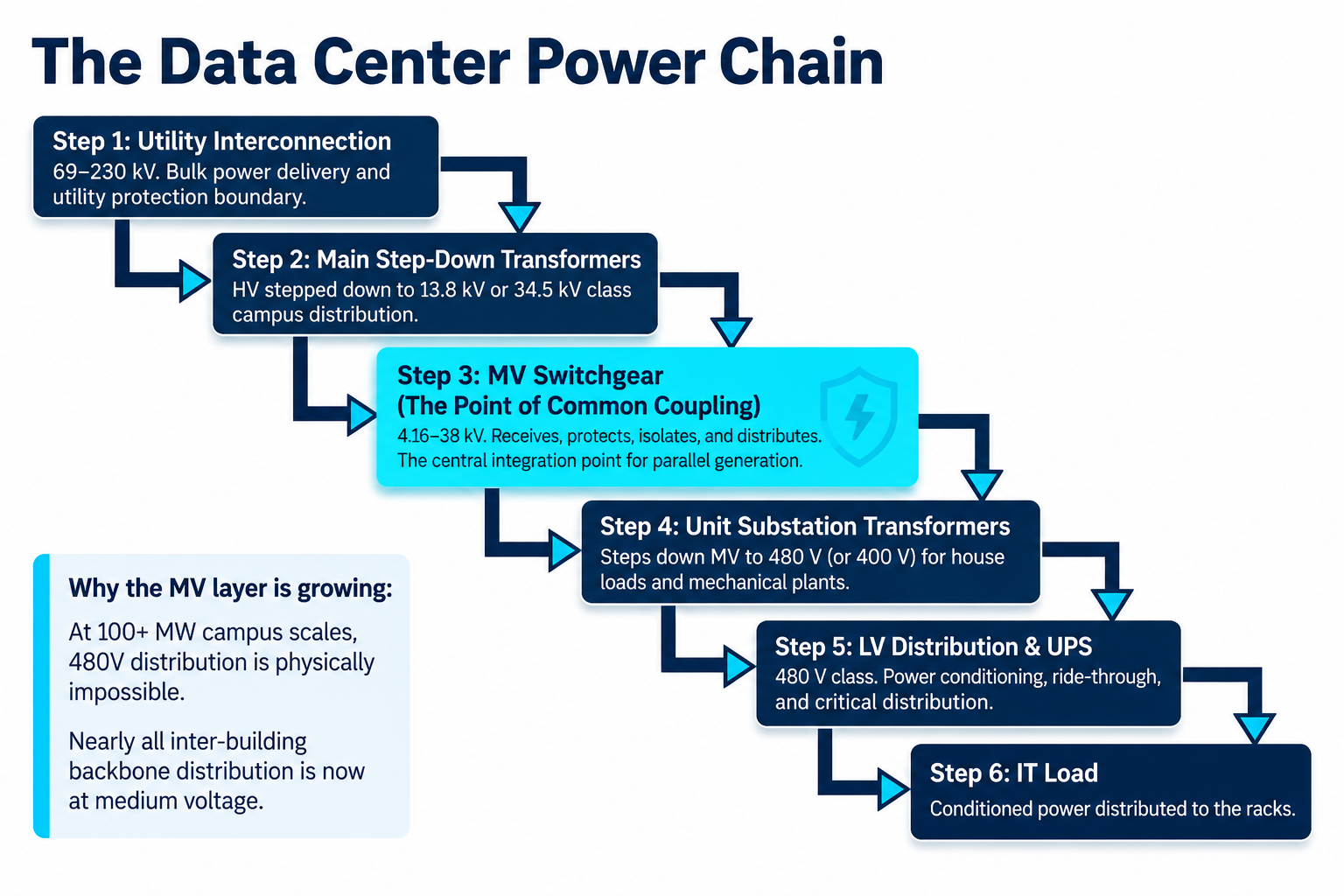
A typical utility-fed data center power chain flows from the utility interconnection through medium-voltage distribution, transformation, low-voltage distribution, power conditioning, and finally to the IT load. The MVSG occupies the pivotal position between the sources (utility and generators) and everything the facility owns downstream.
Stage
Typical Voltage
Function
Utility interconnection / substation
69–230 kV (large campuses) or direct MV service
Bulk power delivery, revenue metering, utility protection boundary.
Main step-down transformers
HV to 13.8 kV / 34.5 kV class
Transform transmission or subtransmission voltage to campus distribution voltage.
MV switchgear (MVSG)
4.16–38 kV (13.8 kV and 34.5 kV most common)
Receive, protect, isolate, control, meter, and distribute MV power; integrate generators.
Unit substation transformers
MV to 480 V (or 400 V)
Step down to utilization voltage for UPS, mechanical plant, and house loads.
LV switchgear / switchboards
480 V class
LV distribution, UPS input/output switching, mechanical distribution.
UPS and critical distribution
480 V to PDU level
Ride-through, conditioning, and distribution to IT racks.
Two trends are pushing more engineering weight onto the MV layer. First, campus scale: at 100+ MW, distributing at 480 V is physically impossible, so nearly all inter-building and even in-building backbone distribution is now at medium voltage, sometimes with MV UPS or MV-connected generation. Second, on-site generation integration: standby diesel or gas generation, and increasingly fuel cells and BESS, are paralleled at the MV bus, making the MVSG the point of common coupling for multiple sources and the natural home for source-transfer automation.
3. Anatomy of an MV Switchgear Lineup
An MV switchgear lineup is an integrated assembly of standardized vertical sections (cubicles), each performing a specific function, connected by a continuous busbar system and supervised by a protection, control, and monitoring layer. Understanding the lineup section by section is the foundation for safe operation, effective maintenance, and fast fault response.
3.1 Incoming Sections
Incoming sections receive power from the utility network or from on-site generation and connect it to the busbar. Each incoming section typically contains a withdrawable (drawout) vacuum circuit breaker, current transformers (CTs) for protection and metering, voltage transformers (VTs) for protection, synchronizing, and metering, and surge protection. In dual-source architectures there are two incoming sections — one per source — each sized to carry the full facility load when the other source is out of service.
The incoming breaker is the interface between the external source and everything the facility owns. Its protection package must coordinate upward with the utility's protection (or the upstream main transformer protection) and downward with feeder protection on the same bus. Directional overcurrent and reverse-power elements are commonly applied where on-site generation can back-feed toward the source.
O&M focus:
source availability and power quality monitoring, breaker status and readiness, alarm and trip-event monitoring, protection relay health, and preventive maintenance on the breaker and primary connections.
3.2 Busbar System
The busbar is the copper (or aluminum) backbone of the lineup. It carries the total load current of every connected feeder and distributes power along the length of the switchgear. Bus is insulated and braced to withstand the mechanical forces of maximum through-fault current — forces that scale with the square of the current. Bus joints are the most common thermal weak point in aging switchgear: a joint that loses clamping force develops resistance, heats, oxidizes, and accelerates toward failure.
O&M focus:
infrared or continuous thermal monitoring of joints and connections, verification of connection tightness at planned outages, insulation condition assessment (including partial discharge survey on higher-voltage lineups), and arc-flash risk management for any work near the bus zone.
3.3 Bus Coupler (Bus Tie)
The bus coupler — also called the bus tie — connects two busbar sections so load can be transferred between them. It is the keystone of the classic main-tie-main architecture. In a dual-bus data center configuration, the tie normally operates open, so each incoming source serves its own bus section independently; the tie closes only under specific, controlled conditions — typically loss of one source, or a planned transfer to release one source for maintenance.
Tie operation raises two engineering questions that must be answered in design, not discovered in operation. First, paralleling: if the tie closes while both incomings are closed (closed-transition transfer), the two sources are momentarily paralleled, which requires synchronism-check supervision (device 25) and a short-circuit duty check, because paralleled sources can raise available fault current beyond equipment ratings. Second, interlocking: a two-out-of-three logic (of the two mains and the tie, only two may be closed at once) is commonly enforced by a combination of electrical interlocks and mechanical key interlocks, unless the design has been explicitly rated and studied for continuous parallel operation.
O&M focus:
automatic and manual operation testing, interlock and transfer-logic validation, synchronizing scheme checks where applicable, and periodic verification of the transfer conditions and timers against the current facility configuration.
3.4 Outgoing Feeder Sections
Outgoing feeders supply medium-voltage power to the unit substation transformers that in turn feed critical LV systems — UPS inputs, mechanical cooling plant, and house power. Each feeder section contains its own breaker, CTs, protection relay, and metering, so every downstream transformer is individually protected and its loading individually visible. Feeder protection must sit below the incoming protection and above the transformer's own protection in the coordination hierarchy, so a transformer or cable fault trips only the affected feeder and nothing else.
O&M focus:
load monitoring and trending against feeder and transformer ratings, protection settings management under configuration control, breaker operation counts and condition, and disciplined fault investigation whenever a feeder relay operates.
3.5 Instrument Transformers and Metering
CTs and VTs are the sensory system of the switchgear. CT ratio, accuracy class, and saturation performance must be matched to the protection functions they serve; a CT that saturates during a close-in fault can delay or misdirect a trip. VTs provide the voltage references for protection (27/59/81 elements), synchronism check, power metering, and automation logic. Data center owners increasingly specify revenue-class metering on incomings and feeder-level power-quality monitoring to support capacity management and SLA reporting.
3.6 Protection, Control, and Monitoring
The protection, control, and monitoring layer is the brain of the MVSG. Modern lineups use microprocessor-based multifunction relays on every breaker, communicating over a station network to a SCADA or electrical power monitoring system (EPMS). The system continuously monitors currents, voltages, breaker status, and equipment health; detects faults; and ensures selective isolation — clearing the faulted zone without disturbing healthy parts of the system. Section 6 treats protection design in depth.
O&M focus:
relay health and self-diagnostic supervision, event and alarm log review, settings validation against the coordination study of record, firmware and configuration management, and communication-network status.
Keentel Insight
Treat the lineup as a set of protection zones, not a row of cabinets. Every maintenance plan, switching order, and arc-flash boundary should be written zone by zone — incoming zone, bus zone, feeder zone — because that is how the protection sees the system and how faults will actually be cleared.
4. Redundancy Architectures: From Single Bus to 2N
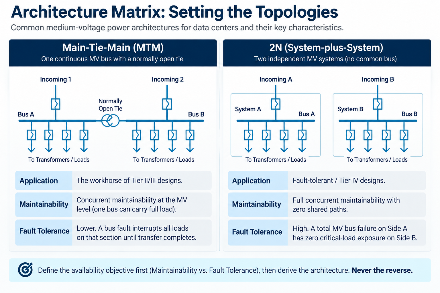
The single-line architecture of the MV system is the single most consequential reliability decision in the electrical design. It determines whether the facility can survive a source loss without interruption, whether any MV component can be maintained without shedding critical load, and how faults propagate — or are contained.
4.1 Common MV Architectures
Architecture
Description
Data Center Application
Single bus, single source
One incoming, one bus, radial feeders.
Non-critical or edge sites only; no source or bus redundancy.
Main-tie-main (MTM)
Two incomings, two bus sections, normally-open tie.
The workhorse of Tier II designs; each bus can carry full load; concurrent maintainability at the MV level.
Double-ended with dual tie
Two incomings, sectionalized bus, two ties.
Allows a bus section outage while retaining source redundancy on the remaining sections.
Ring bus / loop
Feeders served from a loop with sectionalizing switches.
Campus MV distribution between buildings; isolates cable faults without losing a building.
2N (system-plus-system)
Two fully independent MV systems (A and B) from separate sources to separate transformer sets.
Tier IV / fault-tolerant designs; no shared MV component between A and B paths.
4.2 Matching Architecture to Availability Objectives
Concurrent maintainability — the ability to take any component out of service on a planned basis without impacting critical load — requires that every MV element (incoming breaker, bus section, tie, feeder) have a maintenance bypass path. Main-tie-main achieves this for sources and, with dual-ended transformer feeds, for feeders; the bus sections themselves become the residual constraint, which is why higher-availability designs sectionalize further or move to full 2N.
Fault tolerance — riding through an unplanned failure of any single component without load impact — is a stricter test. A bus fault on a shared MTM lineup interrupts every load on that bus section until transfer completes; only a true 2N separation (independent lineups, separate rooms or at least fire-rated separation, no shared control power or automation) contains an MV bus failure without any critical-load exposure. This is the fundamental reason fault-tolerant facilities carry the A/B separation all the way up to the medium-voltage and source level, not just from the UPS down.
Physical and systems separation matters as much as the single-line diagram: independent DC control-power batteries per lineup, physically separated raceway for A and B feeders, separate relay and automation networks, and no common-mode dependencies in the EPMS. Many facilities that are 2N on paper are N on control power.
Keentel Insight
Audit the auxiliary systems with the same rigor as the primary system. Shared station batteries, a common automation PLC, or A and B feeders in the same duct bank are the classic hidden single points of failure that quietly convert a 2N design into an N design.
5. Equipment Classes, Ratings, and Construction
5.1 Metal-Clad vs. Metal-Enclosed
In the ANSI/IEEE world, metal-clad switchgear (IEEE C37.20.2) provides compartmentalization of the breaker, bus, and cable sections with grounded metal barriers, drawout vacuum breakers, insulated bus, and automatic shutters — features that directly support maintainability and internal fault containment. Metal-enclosed interrupter switchgear (IEEE C37.20.3) uses load-interrupter switches and fuses in a simpler, lower-cost construction, generally applied at smaller sites or for simple transformer primary protection rather than as the main distribution asset of a large data center. IEC-market equivalents are classified under IEC 62271-200, with loss-of-service-continuity (LSC) categories and partition classes defining comparable compartmentalization concepts.
5.2 Insulation Medium: AIS, GIS, and SF6-Free Designs
Air-insulated switchgear (AIS) remains the default for 5–15 kV class data center lineups. Gas-insulated switchgear (GIS) offers a dramatically smaller footprint, sealed primary parts that are immune to dust and humidity, and reduced maintenance — attractive at 34.5 kV and above, in space-constrained urban facilities, or in harsh environments. The industry is actively moving away from SF6 toward vacuum interruption with clean-air or fluoronitrile-based insulation; owners specifying new campuses should weigh the sustainability reporting impact of SF6 inventory against the maturity and serviceability of the newer gas-free platforms.
5.3 Core Ratings
Rating
Typical Data Center Values
Engineering Notes
Rated maximum voltage
4.76 / 15 / 27 / 38 kV classes
Selected for the distribution voltage; 15 kV class for 13.8 kV systems is most common.
Continuous current (main bus)
1200 / 2000 / 3000 / 4000 A
Size for ultimate build-out plus transfer scenarios where one bus carries full facility load.
Short-circuit (interrupting) rating
25 / 31.5 / 40 / 50 kA
Must exceed maximum available fault current including all paralleled sources and motor contribution.
Basic insulation level (BIL)
60 / 95 / 125 / 150 kV
Coordinated with surge arresters and cable insulation.
Internal arc classification
Arc-resistant Type 2B (C37.20.7) / IAC AFLR (IEC)
Contains internal arc byproducts away from personnel on all accessible sides.
Two rating pitfalls recur in data center practice. First, momentary paralleling during closed-transition transfer: with both utility incomings and the tie closed, fault current from both sources sums on the bus, and the equipment must be rated for that condition even if it lasts only cycles. Second, growth: AI-era campuses routinely double planned density mid-design; specifying bus continuous current and fault duty for the ultimate phase — not the day-one phase — is far cheaper than replacing switchgear in a live facility.
5.4 Arc-Resistant Construction and Personnel Safety
Arc-resistant switchgear per IEEE C37.20.7 is tested to contain and redirect the pressure wave and incandescent gases of an internal arcing fault through plenums and vents away from operators. Type 2B accessibility maintains protection with low-voltage instrument compartment doors open — important because relay work is the most common live-lineup activity. Arc resistance complements, but does not replace, arc-energy reduction in the protection design (Section 6.4): the enclosure protects people from the blast; the protection limits the energy and the damage.
6. Protection and Control Design
6.1 Protection Philosophy: Selectivity First
Data center MV protection is designed around one governing principle: a fault must be cleared by the nearest upstream device, and only that device, as fast as the coordination allows. Selectivity preserves the maximum amount of healthy system; speed limits equipment damage and arc energy. These two goals trade against each other in classic time-coordinated schemes, which is why modern designs supplement time-overcurrent coordination with bus differential, zone-selective interlocking, and arc-flash detection to get both.
6.2 Core Protection Functions
ANSI Device
Function
Typical Application in the MVSG
50/51, 50N/51N
Instantaneous / time overcurrent, phase and ground
Every incoming and feeder breaker; the coordination backbone.
87B
Bus differential
High-speed, inherently selective clearing of bus-zone faults on critical lineups.
87T
Transformer differential
Larger unit substation or main transformers fed from the lineup.
27 / 59
Undervoltage / overvoltage
Source supervision for transfer schemes, equipment protection.
81 O/U
Frequency
Generator-connected buses; load-preservation logic.
25
Synchronism check
Supervises tie or incoming close during closed-transition transfer and generator paralleling.
50BF
Breaker failure
Backup tripping of adjacent zone if a breaker fails to clear.
67 / 32
Directional overcurrent / reverse power
Buses with generation; prevents undetected back-feed.
AFD
Arc-flash detection (light + current)
Trips in a few cycles on internal arc; major incident-energy reduction.
6.3 Coordination in a Compressed System
Data center MV systems are electrically short — from utility incoming to transformer primary may be only two or three coordination steps — yet the consequences of miscoordination are extreme. The coordination study must reconcile utility upstream requirements (which cap how slow the incoming can be) with transformer damage curves and inrush (which floor how fast a feeder can be). Bus differential (87B) is the cleanest way out of the squeeze: it clears bus faults in a few cycles regardless of the time-overcurrent ladder, letting feeder and incoming overcurrent settings coordinate comfortably. Zone-selective interlocking (ZSI) achieves a similar effect at lower cost by letting a feeder relay block the incoming's fast element when the fault is in the feeder's zone.
6.4 Arc-Flash Mitigation
Incident energy at the MV lineup is governed by fault current and clearing time (per IEEE 1584 methods). Because fault current is fixed by the system, clearing time is the lever. Effective mitigation layers include arc-flash detection relays combining light and current criteria (clearing in 2–4 cycles), maintenance-mode switches that temporarily enable an instantaneous element while personnel work near the equipment, bus differential protection, remote racking and remote switching so operators stand outside the arc-flash boundary, and arc-resistant construction as the last line of defense. Every layer should be reflected in the facility's arc-flash study and labeling, and the maintenance-mode procedure must be written into switching orders — a mitigation feature nobody engages protects nobody.
6.5 Automation, Transfer Schemes, and Interlocking
The main-tie-main automatic transfer scheme is the signature automation of the data center MVSG. On loss of a source (supervised by 27 elements with security timers to ride through remote faults), the scheme opens the dead incoming and closes the tie, re-energizing the affected bus from the healthy source in a defined time. Design decisions that must be made deliberately include open vs. closed transition for planned transfers, transfer inhibit conditions (bus fault lockout — never transfer onto a faulted bus), load-shed or staged-restart supervision for transformer inrush on re-energization, and manual return-to-normal philosophy. Generator integration adds paralleling logic, load ramping, and protection mode changes (grounding and fault-level differences between utility and generator sources).
Interlocking enforces the safe operating states: electrical interlocks in the transfer logic, mechanical key interlocks as the human-proof backstop, and drawout position interlocks native to metal-clad construction. On IEC 61850-based lineups, GOOSE messaging increasingly carries interlocking and ZSI signals over the station network; the design must then treat network health as protection-critical, with message supervision and defined fail-safe states.
Keentel Insight
Automatic transfer schemes fail in the corners, not the center. The scheme that works perfectly in the factory test can misoperate on a real system event — a slow-decaying bus residual voltage, a simultaneous utility dip on both sources, a VT fuse failure. Demand a documented cause-and-effect matrix and test every row of it during commissioning, including the ugly rows.
7. Operations and Maintenance: Keeping the Backbone Healthy
7.1 Why MVSG O&M Is Different in a Data Center
Data center MV switchgear runs continuously loaded, cannot tolerate casual outages, and is operated by teams whose daily work is dominated by mechanical and IT systems. The O&M program must therefore be deliberate: condition-based where possible, outage-efficient when de-energized work is required, and procedural everywhere. The payoff is direct — MV switchgear maintained on a disciplined program is among the most reliable equipment in the facility; neglected, its failures are among the most catastrophic.
7.2 Section-by-Section O&M Priorities
Section
Continuous / Online
Periodic / Outage-Based
Incoming sections
Source PQ monitoring, breaker readiness, relay self-diagnostics,
trip-circuit supervision.
Breaker timing and contact-resistance tests,
primary connection inspection, relay secondary injection.
Busbar system
Thermal monitoring (IR windows or continuous sensors),
PD monitoring on high-voltage bus.
Torque/joint verification, insulation resistance,
cleaning, PD survey.
Bus coupler
Interlock status, transfer-scheme health,
control-power supervision.
Functional transfer tests, sync-check verification,
timer validation.
Outgoing feeders
Load trending vs. ratings, breaker operation counters,
event log review.
Breaker service by duty/age, CT/VT checks,
settings audit vs. study of record.
Protection & control
Relay watchdog alarms, comms network status,
event/alarm review.
Full functional trip tests, firmware/config management,
battery and DC system tests.
7.3 Condition Monitoring Technologies
- Thermal — Continuous thermal sensing at bus joints and cable terminations (or IR windows for safe periodic scans) catches the dominant slow-failure mode of the bus system.
- Partial discharge — Partial discharge (PD) monitoring — online sensors or periodic surveys — detects insulation degradation years before failure, particularly valuable at 15 kV class and above and in humid environments.
- Breaker analytics — Breaker condition indicators — operation counts, charging-motor current signatures, travel/timing analysis — move breaker overhaul from calendar-based to condition-based.
- Control power — DC control power is the silent kingmaker: a failed station battery makes every protection and transfer function inoperative simultaneously. Battery monitoring and load testing belong at the top of the program, not the bottom.
7.4 Safe Work Practices
MV switchgear work is governed by NFPA 70E arc-flash and shock protection requirements. Racking breakers is historically the highest-risk routine task; remote racking devices and arc-resistant construction have transformed that risk profile and should be standard in new facilities. Every switching evolution — planned transfer, isolation for maintenance, return to normal — should follow a written, peer-reviewed switching order, with the maintenance-mode protection setting engaged whenever personnel work within the arc-flash boundary of energized equipment.
7.5 What Disciplined MVSG O&M Delivers
- Continuous power to critical IT loads through source disturbances and planned work.
- Reduced risk of unplanned downtime from the highest-consequence failure modes in the facility.
- Safe switching and maintenance with predictable, bounded risk to personnel.
- Extended equipment lifecycle — 25–30 years is achievable on a condition-based program.
- Demonstrable compliance with reliability and safety frameworks (Uptime Institute objectives, ISO management systems, IEEE/NETA maintenance standards, NFPA 70E).
8. Commissioning: Proving the System Before It Matters
Commissioning is where the MVSG design is proven — or where its latent defects are found at the only acceptable time. A rigorous program spans five levels: factory acceptance testing (FAT) of the assembled lineup including functional automation tests; site acceptance and pre-energization testing per ANSI/NETA ATS (insulation resistance, contact resistance, breaker timing, CT/VT ratio and polarity, primary or secondary injection of every protection element); protection settings validation against the coordination study of record; functional performance testing of the complete transfer scheme against the cause-and-effect matrix, including failure-mode rows; and integrated systems testing (IST), where the MVSG, generators, UPS, and mechanical plant are exercised together through pull-the-plug scenarios at full facility load banks.
Settings management deserves special emphasis: the relay settings energized on day one must be the studied settings, under configuration control, with as-left files archived. A surprising fraction of real-world misoperations trace to settings that drifted from the study — placeholder settings never updated, or field changes never fed back into the study.
Keentel Insight
Insist that the MV transfer scheme be tested at the switchgear with primary sources, not only simulated in the factory. Utility source behavior, VT fusing, DC system sags, and real breaker timing all differ from the test floor — and integrated systems testing is the only stage that exercises them together.
9. Design Checklist for Data Center Owners and Engineers
- Architecture — Define the availability objective first (concurrent maintainability vs. fault tolerance) and derive the MV architecture from it — not the reverse.
- Ratings — Rate bus continuous current and short-circuit duty for the ultimate build-out and for paralleled-source transfer conditions.
- Arc safety — Specify arc-resistant (Type 2B / IAC AFLR) construction and layer protective arc-energy reduction: AFD relays, maintenance mode, 87B or ZSI, remote racking.
- Protection — Require a complete coordination and arc-flash study before settings are energized, and put settings under configuration control from day one.
- Automation — Document the transfer scheme in a cause-and-effect matrix and test every row at commissioning, including failure modes.
- Separation — Eliminate hidden common modes: independent DC systems per lineup, separated raceways, independent automation and relay networks for A and B systems.
- Maintainability — Design for maintainability: drawout breakers, IR windows, online PD provisions, spare cubicles, and a critical-spares strategy including a spare breaker per frame size.
- O&M by design — Plan the O&M program during design — monitoring points, test access, and switching procedures are far cheaper to provide on paper than to retrofit.
10. Standards and References Landscape
Domain
Key Standards / Frameworks
Switchgear assemblies
IEEE C37.20.2 (metal-clad), C37.20.3 (metal-enclosed),
C37.20.7 (arc-resistant); IEC 62271-200.
Circuit breakers
IEEE C37.04 / C37.06 / C37.09 (ratings and testing);
IEC 62271-100.
Protection & relaying
IEEE C37.90 series, C37.2 (device numbers),
IEC 61850 (communications), IEEE 242 (coordination).
Arc flash & electrical safety
IEEE 1584 (incident energy),
NFPA 70E,
OSHA 1910 Subpart S.
Installation & code
NFPA 70 (NEC) Articles 490 and 495 (formerly 490),
utility interconnection requirements.
Testing & maintenance
ANSI/NETA ATS (acceptance),
ANSI/NETA MTS (maintenance),
IEEE 3007 series.
Data center reliability
Uptime Institute Tier objectives,
TIA-942,
ISO facility management frameworks.
11. How Keentel Engineering Supports Data Center MV Systems
Keentel Engineering LLC provides end-to-end medium-voltage engineering for data centers and other mission-critical facilities: MV system architecture and single-line development; short-circuit, coordination, and arc-flash studies; switchgear specification and procurement support; protection settings development and relay programming; transfer-scheme logic design and cause-and-effect documentation; commissioning and integrated systems testing support as owner's engineer; and O&M program development including condition-monitoring strategy and switching procedures. Our team also supports utility interconnection for data center campuses — from point-of-interconnection studies through NERC compliance — so the MV design is coordinated with the transmission-side realities that shape it.
Whether you are planning a new campus, expanding an operating facility, or hardening an existing MV lineup against arc-flash and reliability risk, Keentel brings licensed professional engineering judgment and current, standards-based practice to the highest-consequence layer of your power system.
12. Key Takeaway
An MV switchgear lineup is an integrated system of switching, protection, control, and monitoring engineered to deliver safe, reliable, and uninterrupted power to mission-critical facilities. Know your MV switchgear — its architecture, its protection zones, its transfer logic, and its condition — and operate it with discipline, and your data center stays on. Neglect it, and no quantity of downstream redundancy will save you. The medium-voltage layer is where data center reliability is truly won or lost.
Case Studies
The following case studies are drawn from representative mission-critical engineering engagements. All client, project, location, and personnel identifiers have been removed or generalized to protect confidentiality.
Case Study 1: Main-Tie-Main MV Design for a Hyperscale Campus Expansion
Parameter
Detail
Facility
Multi-building hyperscale data center campus, approx. 60 MW critical
IT load at build-out.
Scope
MV architecture development, 34.5 kV and 13.8 kV switchgear
specification, protection coordination and arc-flash studies,
transfer-scheme design.
System
Dual utility feeds, 34.5 kV campus ring, main-tie-main 13.8 kV
lineups per building, arc-resistant metal-clad switchgear.
Challenge. The owner's phase-one design had sized bus continuous current and short-circuit duty for the initial 20 MW deployment. Mid-design, planned rack densities more than doubled. Preliminary short-circuit analysis showed that closed-transition transfers at ultimate build-out would exceed the specified 25 kA switchgear rating during the paralleled interval, and the two-step coordination between feeder and incoming relays left no margin against the utility's upstream clearing requirements.
Approach. The MV single-line was re-architected around 40 kA, 3000 A arc-resistant lineups rated for the ultimate phase, with bus differential (87B) protection added to each lineup to decouple bus-fault clearing from the time-overcurrent ladder. The transfer scheme was formalized in a cause-and-effect matrix covering source loss, bus-fault lockout, VT failure, and DC-loss scenarios. Feeder settings were coordinated against transformer damage and inrush curves, and maintenance-mode arc-energy reduction settings were engineered for every bus.
Outcome. The final design achieved full selectivity with utility approval on the incoming settings, closed-transition transfer capability within equipment ratings at ultimate build-out, and calculated incident-energy reductions of more than 80 percent at the lineups in maintenance mode. The owner avoided a mid-life switchgear replacement that the phase-one sizing would have forced.
Case Study 2: Arc-Flash Mitigation Retrofit on an Operating Colocation Facility
Parameter
Detail
Facility
Operating multi-tenant colocation facility, approx. 15 MW critical
load, 15 kV class MV distribution.
Scope
Arc-flash study refresh, protection retrofit design, maintenance-mode
implementation, switching procedure development.
System
Legacy (20+ year) metal-clad switchgear, dual incomings with manual
tie, electromechanical relays on feeders.
Challenge. An updated IEEE 1584 study showed incident energy at the main lineup exceeding the practical limits of available PPE, driven by slow electromechanical relay clearing and settings that had drifted from any study of record. The facility could not accept extended outages, and full switchgear replacement was not fundable in the near term.
Approach. A staged retrofit replaced feeder and incoming relays with multifunction microprocessor relays incorporating arc-flash detection (light plus current) and a supervised maintenance-mode instantaneous group, executed bus section by bus section using the tie to keep tenants energized. CT circuits were verified and settings were rebuilt from a new coordination study. Remote racking equipment and rewritten switching orders completed the personnel-safety layer.
Outcome. Calculated incident energy at the lineup dropped from beyond PPE limits to within standard arc-rated PPE levels in maintenance mode, with normal-mode selectivity fully preserved. The retrofit was completed without any tenant load interruption, and the facility adopted a configuration-controlled settings and testing program aligned with ANSI/NETA MTS.
Case Study 3: Owner's Engineer for MV Commissioning with Generator Paralleling
Parameter
Detail
Facility
New-build enterprise data center, approx. 24 MW critical load,
13.8 kV distribution with paralleled standby generation.
Scope
Owner's engineer services: factory and site acceptance oversight,
protection settings validation, transfer and paralleling scheme
testing, integrated systems testing support.
System
Main-tie-main 13.8 kV arc-resistant switchgear,
six-unit generator plant paralleling to the MV bus,
IEC 61850 GOOSE-based interlocking.
Challenge. Factory testing had validated the transfer scheme against simulated inputs only. During site review, the cause-and-effect matrix was found to omit several credible failure modes — VT fuse loss during transfer, DC system sag under simultaneous breaker operations, and GOOSE network degradation affecting interlocking — and generator-mode ground-fault protection had not been verified against the plant's actual grounding configuration.
Approach. The commissioning plan was expanded to test every matrix row at the switchgear with primary sources, including deliberately induced failure cases. Secondary injection proved each protection element in both utility and generator source modes; GOOSE message supervision and fail-safe states were configured and demonstrated. Integrated systems testing exercised pull-the-plug transfers and generator paralleling at full load-bank load, with relay event records analyzed after every evolution.
Outcome. Testing surfaced and resolved a transfer misoperation path (a security timer set below the utility's reclose interval) and a generator-mode ground-fault sensitivity gap — both before the facility carried live load. The owner accepted the system with a fully executed cause-and-effect record, as-left settings archive, and a baseline breaker-timing and PD dataset for the future condition-based maintenance program.
FAQ
Q: What is MV switchgear and why is it the first major distribution asset in a data center?
Medium-voltage switchgear (MVSG) is the assembly of breakers, busbar, instrument transformers, and protection/control equipment that receives power from the utility or on-site generation and distributes it — typically at 4.16 to 38 kV — to the transformers feeding the facility. It sits immediately downstream of the source, so every watt reaching the IT load passes through it. Its job is to receive, isolate, protect, control, meter, and distribute power continuously.
Q: What voltage levels are typical for data center MV distribution?
13.8 kV (15 kV class) is the most common campus distribution voltage in North America, with 34.5 kV increasingly used for large campuses to reduce cable count and losses over distance. 4.16 kV appears in some legacy or mechanical-plant applications. Voltage selection is driven by campus size, load density, utility service voltage, and equipment availability.
Q: What is a main-tie-main configuration and why is it so widely used?
Main-tie-main (MTM) uses two incoming sources, two bus sections, and a normally open tie breaker between them. Each source serves its own bus; if a source is lost or must be maintained, the tie closes and the healthy source carries the whole facility. It delivers source redundancy and concurrent maintainability at the MV level with a single lineup, which is why it is the workhorse of Tier III-class designs.
Q: Why is the bus coupler normally open instead of normally closed?
With the tie open, the two bus sections are electrically independent: a fault on one bus does not disturb the other, available short-circuit current on each bus is limited to one source, and protection coordination is simpler. Closing the tie continuously would parallel the sources, raising fault duty and coupling the buses' fates. The tie therefore closes only under controlled conditions — source loss or planned transfer — unless the system is specifically designed and rated for parallel operation.
Q: What is the difference between open-transition and closed-transition transfer?
Open transition breaks the connection to the first source before closing to the second — a brief, deliberate interruption (typically ridden through by the UPS). Closed transition momentarily parallels both sources before opening the original one, achieving a seamless transfer, but it requires synchronism-check supervision and equipment rated for the combined fault current during the paralleled instant, and utility approval for paralleling.
Q: What is selective protection and why does it matter so much in a data center?
Selectivity means a fault is cleared only by the protective device nearest to it, so the smallest possible portion of the system is de-energized. In a data center, a feeder cable fault should trip only that feeder — never the incoming breaker, which would drop every load on the bus. Selectivity is engineered through the coordination study, relay settings, and schemes like bus differential and zone-selective interlocking.
Q: What is arc-resistant switchgear and do I still need arc-flash mitigation with it?
Arc-resistant switchgear (IEEE C37.20.7) is built and tested to channel the blast and gases of an internal arcing fault away from personnel through plenums and vents. It protects people standing at the equipment; it does not reduce the arc energy or the equipment damage. Protective mitigation — arc-flash detection relays, maintenance-mode instantaneous settings, bus differential, remote racking — is still required. The two are complementary layers, not alternatives.
Q: How does bus differential (87B) protection improve a data center lineup?
87B compares current entering and leaving the bus zone; any difference means an internal bus fault, which it clears in a few cycles without waiting for time-overcurrent coordination. That gives extremely fast, inherently selective bus protection — reducing arc energy and equipment damage — while allowing incoming and feeder overcurrent settings to coordinate comfortably.
Q: What does an automatic transfer scheme check before it acts?
A well-designed scheme verifies that the loss of source is real and sustained (undervoltage elements with security time delays), that the affected bus is healthy (transfer is locked out for a bus fault — you never transfer onto a fault), that the alternate source is available and within limits, and that interlocking states permit the operation. For closed transition it also verifies synchronism across the tie.
Q: What routinely fails first in aging MV switchgear?
Statistically: bus and cable connections (thermal degradation of joints), breaker operating mechanisms (lubrication hardening and mechanism wear, especially in seldom-operated breakers), insulation systems (tracking and partial discharge, accelerated by contamination and humidity), and DC control power (aged station batteries). All four are detectable well in advance by thermal monitoring, breaker timing analysis, PD survey, and battery testing respectively.
Q: How often should MV switchgear be maintained?
Modern practice follows ANSI/NETA MTS intervals adjusted by condition and criticality rather than a fixed calendar alone. In broad terms: continuous or annual online condition monitoring (thermal, PD, relay diagnostics, event review); functional protection and transfer-scheme testing on a 2–3 year cycle; and comprehensive de-energized inspection, cleaning, torque verification, and breaker servicing on a 3–6 year cycle depending on duty, environment, and condition trends.
Q: Can MV switchgear be maintained without shutting down the data center?
Yes — if the architecture was designed for it. In a main-tie-main system, one bus section can be transferred to the other source and de-energized for maintenance while the facility runs. Drawout breakers can be racked out and serviced individually. This is exactly what concurrent maintainability means; facilities without a transfer path must either defer maintenance (accumulating risk) or take load interruptions.
Q: What is the role of IEC 61850 in modern MV switchgear?
IEC 61850 is the communications standard that lets protection relays, controllers, and SCADA/EPMS exchange data and high-speed signals over a station network. GOOSE messaging can carry interlocking, transfer-scheme, and zone-selective-interlocking signals in milliseconds, replacing large amounts of hard wiring. It brings flexibility and rich monitoring, but makes network health protection-critical — designs must supervise message flow and define fail-safe behavior.
Q: How do on-site generators change the MVSG design?
Generator integration adds paralleling and synchronizing logic, directional and reverse-power protection, and often a change in system grounding behavior between utility and generator sources — which affects ground-fault protection settings. Fault current available from generators differs from the utility (and decays with time), so protection must be verified for both source modes. The MVSG becomes the point of common coupling where source-transfer automation lives.
Q: What should an owner require at commissioning of a new MV lineup?
At minimum: ANSI/NETA ATS acceptance testing of every breaker, bus, CT, VT, and relay; primary or secondary injection proof of every protection element; energization of studied settings under configuration control; end-to-end functional testing of the transfer scheme against a documented cause-and-effect matrix, including failure-mode cases; and participation of the MV system in integrated systems testing with generators, UPS, and mechanical plant at full load banks.
About Keentel Engineering
Keentel Engineering is a power systems and
grid interconnection consulting firm headquartered in Tampa, Florida, with offices in Austin, Sacramento, and Baltimore. Our service lines span grid interconnection engineering, substation and transmission design,
power system studies NERC compliance, renewables and BESS engineering, EMT modeling, and
owner's engineer services. We serve developers, independent power producers, utilities, and large-load customers across North American RTO/ISO footprints.
| Contact | Details |
|---|---|
| Headquarters | 400 N Ashley Dr STE 2600, Tampa, FL 33602 |
| Phone | (813) 389-7871 |
| contact@keentelengineering.com | |
| Florida Firm Registration | No. 36853 |
| Additional Offices | Austin, TX • Sacramento, CA • Baltimore, MD |

About the Author:
Sandip "Sonny" R. Patel, P.E.
IEEE Senior Member · Founder & CEO, Keentel Engineering
In 1995, Sonny Patel earned his Electrical Engineering degree from the University of Illinois. But degrees don't build legacies — action does.
For three decades, he has worked the power industry from every side of the table: 16 years as a utility engineer at Exelon/Commonwealth Edison; generation leadership across hydroelectric, industrial steam turbine, and a 9 GW renewable fleet; NERC Regional Entity Senior Compliance Engineer and Audit Team Lead, auditing some of the nation's largest utilities; and testing and commissioning lead on equipment up to 765 kV — the very top of the North American grid.Utility. Generator. Regulator. Consultant. Few engineers have seen all four seats. Fewer still have sat in them.
His experience spans nuclear, hydro, conventional generation, renewables, oil and gas, mining — and today's data centers, where he is authoring a three-book series on data center design. He is a Licensed Professional Engineer in six states and a Licensed Electrical Contractor in Florida (Unlimited EC) — he doesn't just design the work; he's qualified to stand behind its execution.Today, as Founder and CEO of Keentel Engineering, Sonny leads a nationwide team of engineers delivering substation design, power system studies, NERC compliance, and commissioning — done right, coast to coast.Three decades. Every side of the table. One standard: accountable engineering.
Services

Let's Discuss Your Project
Let's book a call to discuss your electrical engineering project that we can help you with.
About the Author:
Sandip "Sonny" R. Patel, P.E.
IEEE Senior Member · Founder & CEO, Keentel Engineering
In 1995, Sonny Patel earned his Electrical Engineering degree from the University of Illinois. But degrees don't build legacies — action does.
For three decades, he has worked the power industry from every side of the table: 16 years as a utility engineer at Exelon/Commonwealth Edison; generation leadership across hydroelectric, industrial steam turbine, and a 9 GW renewable fleet; NERC Regional Entity Senior Compliance Engineer and Audit Team Lead, auditing some of the nation's largest utilities; and testing and commissioning lead on equipment up to 765 kV — the very top of the North American grid.
Utility. Generator. Regulator. Consultant. Few engineers have seen all four seats. Fewer still have sat in them.
His experience spans nuclear, hydro, conventional generation, renewables, oil and gas, mining — and today's data centers, where he is authoring a three-book series on data center design. He is a Licensed Professional Engineer in six states and a Licensed Electrical Contractor in Florida (Unlimited EC) — he doesn't just design the work; he's qualified to stand behind its execution.
Today, as Founder and CEO of Keentel Engineering, Sonny leads a nationwide team of engineers delivering substation design, power system studies, NERC compliance, and commissioning — done right, coast to coast.Three decades. Every side of the table. One standard: accountable engineering.
Leave a Comment
Thank you for contacting us.
We will get back to you as soon as possible.
We will get back to you as soon as possible.
Oops, there was an error sending your message.
Please try again later.
Please try again later.
Related Posts

By SANDIP R PATEL
•
October 13, 2026
Plan data center capacity with land screening, MW-per-acre estimates, grid power availability and interconnection feasibility studies from Keentel Engineering.

By SANDIP R PATEL
•
October 11, 2026
Learn which fault produces the highest current at a bus, why SLG faults can exceed three-phase faults, and how symmetrical components determine fault duty.

By SANDIP R PATEL
•
October 11, 2026
Learn why zero-sequence current pulsates in the dq0 frame, how Park's transformation works, and how inverter controls handle unbalance and ground faults.

By SANDIP R PATEL
•
October 11, 2026
Explore grid inertia, RoCoF and frequency response, with swing equation calculations, frequency nadir analysis and US power system simulation examples.

By SANDIP R PATEL
•
October 11, 2026
Learn transient stability analysis, swing equation, equal-area criterion and critical clearing time with a 345 kV worked example and NERC TPL-001 guidance.

By SANDIP R PATEL
•
October 11, 2026
Learn why inverter controls become unstable in weak grids, how PLL bandwidth and SCR affect stability, and how PSCAD EMT studies identify and mitigate oscillations.

By SANDIP R PATEL
•
October 11, 2026
Learn how STATCOMs improve voltage stability and prevent FIDVR. Explore reactive power sizing, delayed fault clearing, NERC criteria and 138 kV simulation results.

By SANDIP R PATEL
•
October 10, 2026
Learn BESS DC sizing with power, energy, current and C-rate calculations, battery losses, degradation and a 100 MW/400 MWh utility-scale example.

By SANDIP R PATEL
•
October 10, 2026
Learn how BESS ROI is calculated using peak shaving, energy arbitrage, power quality and battery storage economics, with a practical 5 MW/10 MWh example.





