1. Executive Summary
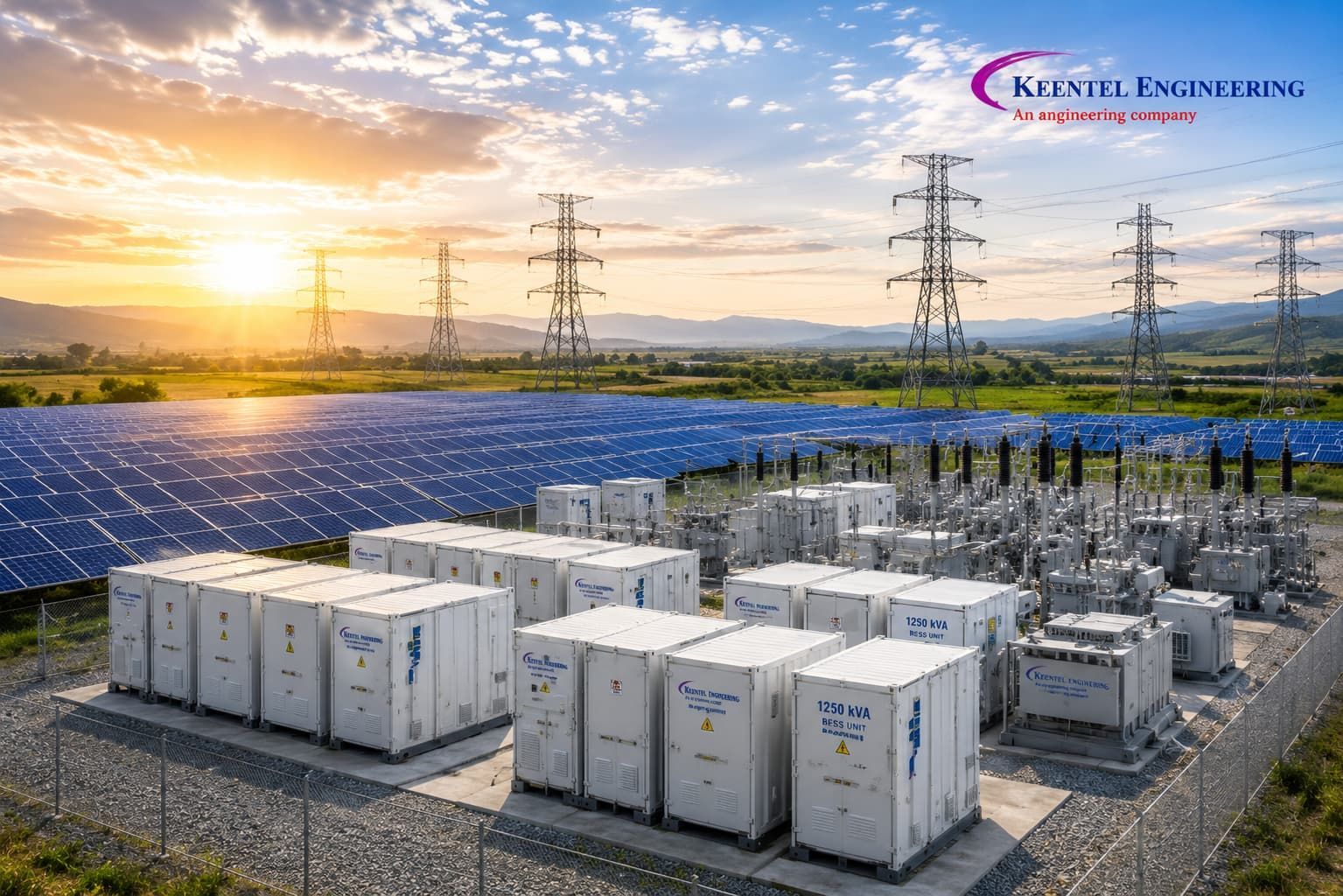
The Client, an independent power producer developing utility-scale storage under a long-term tolling arrangement, required a standalone front-of-meter battery energy storage facility interconnecting to the regional transmission network at 138 kV. The asset was procured explicitly as a grid support asset rather than as an adjunct to a generating plant. That distinction shaped everything that followed: there was no host generator to hide behind, no shared interconnection agreement, and no fixed operating pattern. The facility had to inject, absorb, regulate and idle on command, and to do so profitably across several concurrent service obligations.
Keentel Engineering Solutions acted as owner's engineer and study authority for a 200 MW / 800 MWh four-hour lithium iron phosphate (LFP) installation, delivered as containerized DC blocks with medium-voltage skid-mounted power conversion systems, collected at 34.5 kV and stepped up through a single 125/167/208 MVA 138/34.5 kV main power transformer into a three-breaker ring bus. Scope covered the design basis, the interconnection and facility study package, protection and control philosophy, primary plant specification, energy storage safety engineering under NFPA 855, degradation and augmentation modelling, and commissioning and model-validation support.
The distinguishing problem was the value stack, not the interconnection. The asset was contracted for energy time-shift, frequency regulation and fast frequency response, spinning and non-spinning reserve, voltage support including dynamic reactive power at zero real power output, black start, transmission congestion relief sufficient to defer a network upgrade, and accredited capacity for resource adequacy. Each service imposes a different and occasionally conflicting engineering requirement. Reconciling them within one plant controller, one transformer specification, one protection scheme and one state-of-charge policy was the core of the engagement.
Figures presented are representative of the delivered design and have been generalized to protect client confidentiality.
The delivered design achieved 86.9 percent AC-to-AC round-trip efficiency inclusive of auxiliary consumption, reactive capability of plus or minus 96 MVAr at zero real power, measured fast frequency response of 118 ms to full output, 1.9 percent total demand distortion against a 4 percent limit, and an augmentation plan holding deliverable energy above 800 MWh for a twenty-year term. The transmission upgrade the facility was partly procured to defer was deferred by at least twelve years, against a nominal avoided capital cost of approximately 165 million in the Owner's currency.
Project at a Glance
| Attribute | Detail |
|---|---|
| Asset type | Standalone front-of-meter battery energy storage substation |
| Voltage levels | 138 kV / 34.5 kV |
| Rating and chemistry | 200 MW / 800 MWh, 4-hour duration, lithium iron phosphate |
| Configuration | 138 kV three-breaker ring bus; 1 x 125/167/208 MVA 138/34.5 kV |
| Services contracted | Arbitrage, regulation, FFR, reserves, voltage support, black start, capacity |
| Keentel scope | Design basis, interconnection and facility studies, protection philosophy, safety engineering, augmentation modelling |
| Headline outcome | 86.9 percent AC-to-AC round-trip efficiency; 12-year transmission deferral |
2. Project Context and Business Drivers
The interconnection point sits on a 138 kV corridor that has changed character over roughly a decade. It was built to move power from a fleet of thermal units toward a load pocket. Those units have progressively retired, and the corridor now imports from a distant renewable-rich area through a path that binds for several hundred hours per year. The transmission owner had a reinforcement in its plan, but it carried a long permitting horizon and considerable public opposition.
The Client's thesis was that a storage asset sited on the load side of the constraint could relieve the binding element by charging off-peak and discharging into the congested hours, while earning ancillary service revenue that a wires solution cannot earn at all. Converting that thesis into a specification was the first task, because a deferral claim is only as credible as the study behind it: the asset must relieve the specific overload, under the contingencies that drive the reinforcement, at the hours those contingencies bind, with a state of charge actually available then.
Three constraints framed the work. The queue position carried fixed study milestones, so the facility study package had to be delivered before final equipment selection. The site is compact, a former industrial parcel with property lines close on two sides, making NFPA 855 spacing and deflagration venting a layout driver rather than a detail. And the tolling obligation ran twenty years while no available chemistry holds nameplate energy that long, so augmentation was a contractual as well as a technical deliverable from the outset. A fourth issue emerged during the studies: the surrounding network had accumulated a large population of inverter-based resources, and while the nominal short-circuit ratio at the point of interconnection was comfortable, the weighted ratio was not. That finding put grid-forming control on the table.
3. Design Basis and Technical Requirements
The design basis was issued in the first eight weeks as a controlled document referenced by every subsequent study, specification and drawing. It was reissued once, at Month 7, to incorporate the UL 9540A large-scale fire test review, which changed the required spacing between storage units and therefore the site layout.
Site and Environmental Design Criteria
| Parameter | Design value |
|---|---|
| Maximum ambient air temperature | 41 °C (35 °C maximum daily average) |
| Minimum ambient air temperature | -22 °C |
| Altitude | 310 m above sea level |
| Design wind speed (3 s gust) | 51 m/s |
| Seismic design category | 0.22 g short-period spectral acceleration |
| Pollution severity | Light to medium per IEC 60815; industrial legacy site |
| Soil resistivity | 95 Ω·m upper layer to 3.0 m; 220 Ω·m lower layer |
| Isokeraunic level | 31 thunderstorm days per year |
The wide ambient range matters more for storage than for a conventional substation. Cell life, usable energy and available power are all temperature dependent, and thermal management must reject heat in summer and add it in winter. The -22 °C minimum drove a heating requirement on the liquid cooling loops that is invisible on a summer energy balance but consumes real auxiliary energy for months of the year.
Standards Register
| Standard | Application |
|---|---|
| NFPA 855 | Installation of stationary energy storage systems |
| UL 9540 / UL 9540A | ESS safety certification; large-scale fire propagation test method |
| NFPA 68 / NFPA 69 | Deflagration venting; explosion prevention systems |
| IEEE Std 1547 / 1547.1 | DER interconnection and conformance test procedures |
| IEEE Std 2800 | Interconnection and interoperability of inverter-based resources |
| IEEE Std 519 | Harmonic control in electric power systems |
| IEEE Std C57.110 | Transformer capability supplying non-sinusoidal load current |
| IEEE Std C57.12.00 / C57.91 | Power transformer requirements; loading guide |
| IEEE Std 80 | Safety in AC substation grounding |
| IEEE Std 1584 | Arc-flash hazard calculation |
| IEEE Std C37.010 / C37.04 | Circuit breaker application and rating structure |
| IEEE Std C37.20.7 | Internal arcing fault testing of metal-enclosed switchgear |
| IEEE Std 693 | Seismic qualification of substation equipment |
| IEC 62933 series | Electrical energy storage systems, safety and performance |
| NERC MOD-026 / MOD-027 | Verification of generator and plant control model data |
The Owner's functional requirements were unusually explicit because the tolling agreement paid for capability rather than energy: 200 MW continuous export and import at the point of interconnection across a state-of-charge window of 10 to 95 percent; 800 MWh deliverable at the point of interconnection at the end of every contract year for twenty years; plus or minus 0.95 power factor at any real power output, including full reactive output at zero real power; fast frequency response reaching full commanded output within 200 ms; black start capability sufficient to energize a defined restoration path; and a single plant controller able to arbitrate between concurrent obligations without operator intervention.
4. Substation Configuration and Single-Line Architecture
4.1 The 138 kV bus scheme
The 138 kV switchyard is a three-breaker ring bus with the line position, the main power transformer position and a future position closed into the ring, and provision for a fourth position.
| Criterion | Ring bus (selected) | Single bus with breaker | Breaker-and-a-half |
|---|---|---|---|
| Breakers for three positions | 3 | 1 | 4.5 |
| Relative capital cost | Baseline | -45 percent | +55 percent |
| Single breaker failure consequence | Loses two positions | Loses everything | Loses one position |
| Maintenance without loss of position | Yes | No | Yes |
| Expandability beyond four positions | Poor | Poor | Good |
One argument decided it: a storage asset earning regulation and reserve revenue is penalized for unavailability in a way an energy-only asset is not, and a single-breaker arrangement turns every breaker maintenance into a full outage of the revenue stream. A ring bus permits breaker maintenance with the plant in service. Breaker-and-a-half was rejected because the facility will never exceed four positions on this parcel, and beyond four a ring becomes operationally awkward — which is why the fourth position was designed in and a fifth was not. That provision is genuine: the ring conductor is terminated to allow breaker insertion without a station outage, foundations, conduit and ground grid extend into the position, and the DC system, station service and SCADA point list were sized for it.
4.2 Collector architecture and the single-transformer decision
The 34.5 kV collector is metal-clad switchgear in two line-ups, connected by a normally closed tie and fed from the transformer through segregated-phase bus duct. Each line-up carries five collector feeders serving groups of DC blocks and their conversion skids, one station service feeder, one grounding transformer position and one spare cubicle.
A single main power transformer for a 200 MW asset is a deliberate reliability decision. Two 104 MVA units would give partial output on loss of one, but at this rating the failure rate of a well-specified transformer is low, outage duration is dominated by procurement rather than installation, and a spare under a shared spares agreement addresses the same risk more cheaply. What the choice does require is that the specification be right, because no redundancy exists to absorb a specification error.
4.3 The value stack and its engineering consequences
The contracted operating modes do not simply coexist. Each drives a distinct requirement, and several conflict.
| Operating mode | Dominant engineering driver | Design consequence |
|---|---|---|
| Energy time-shift / arbitrage | Round-trip efficiency and cycle count | Low-loss transformer, cycle-rated OLTC, thermal design |
| Frequency regulation | Response bandwidth and micro-cycling | Fast plant controller, SOC deadband management |
| Fast frequency response | Sub-200 ms full-output ramp | Local frequency measurement, no round-trip to SCADA |
| Spinning / non-spinning reserve | Guaranteed SOC headroom for the award period | SOC reservation logic in the plant controller |
| Voltage support and Q at night | Continuous reactive output at zero real power | Inverter and transformer rated for reactive-only duty |
| Black start | Grid-forming capability and station autonomy | Islanded auxiliary supply, voltage-source control mode |
| Transmission deferral | Availability during binding hours | Dispatch priority rules, contingency-based study proof |
| Capacity accreditation | Sustained four-hour output at end of life | Augmentation plan and capacity fade modelling |
The clearest conflict is between regulation and reserve. Regulation wants the state of charge mid-range so the asset can move either way; reserve wants headroom biased in one direction for a defined award period; arbitrage wants whichever extreme the price signal justifies. The plant controller resolves this with a hierarchy of reservations rather than a single setpoint, and that logic was specified by Keentel because it is the mechanism by which the value stack either works or does not. The second conflict is thermal: regulation duty is low-energy and high-cycle, arbitrage duty is high-energy and low-cycle, so the transformer, collector cables and cooling system were specified against a composite duty cycle rather than a single rating point.
5. System Studies and Analysis
5.1 Modelling basis
All studies proceeded from one frozen data set. Positive-sequence power flow, contingency analysis, transient stability and the transmission deferral case were performed in PSS®E. Electromagnetic transient work — control interaction, sub-synchronous screening, harmonic resonance with the collector cables, and switching transients — was performed in PSCAD/EMTDC. Siemens PTI tools supported planning-level analysis and the dynamic model validation package submitted under NERC MOD-026 and MOD-027. CYME was used for collector-side analysis, cable ampacity and thermal derating, and the auxiliary distribution.
The Thévenin equivalent at the 138 kV point of interconnection gives 24.6 kA symmetrical rms three-phase fault duty, approximately 5,880 MVA, with an X/R of 14.2. Against a 200 MW plant that is a nominal short-circuit ratio of 29.4. The weighted short-circuit ratio, computed with the interaction factors of the seven other inverter-based resources electrically close to the point of interconnection, is 2.8. That number governs converter stability, and it is why grid-forming control was examined seriously.
5.2 Grid-forming versus grid-following control
A grid-following converter measures the grid voltage angle with a phase-locked loop and injects a controlled current: a current source behind a high impedance, dependent on the grid to define voltage and frequency. A grid-forming converter regulates its own internal voltage magnitude and angle and behaves as a voltage source behind a low impedance; the current it delivers is a consequence rather than a command.
| Attribute | Grid-following | Grid-forming (selected) |
|---|---|---|
| Control basis | PLL-tracked current injection | Internally referenced voltage source |
| Behaviour at low SCR | Degrades below SCR ≈ 2; PLL instability | Stable; contributes system strength |
| Inertial response | Synthetic, PLL-dependent, delayed | Inherent within the control time constant |
| Fault current contribution | 1.1 to 1.2 pu, current-limited | 1.1 to 1.3 pu, then reverts to current limit |
| Model validation burden | Established, moderate | Substantial; EMT model mandatory |
Two formulations were evaluated. Droop-based grid-forming derives internal angle from a power-frequency droop and internal magnitude from a reactive-voltage droop; it is simple and robust. Virtual synchronous machine control implements a swing-equation emulation, presenting an apparent inertia constant and damping term so the response to a frequency disturbance resembles a rotating machine. The Client selected droop-based grid-forming with an explicit inertia emulation loop, because it delivered the required system strength contribution and inertial response without the tuning sensitivity and additional oscillatory mode a full virtual synchronous machine introduces at low short-circuit ratio.
The critical honesty in a grid-forming evaluation concerns fault current. A grid-forming converter behaves as a voltage source only until its current limit is reached, which for a close-in fault occurs within a fraction of a cycle. Beyond that it is a current-limited source contributing roughly 1.1 to 1.3 times rated current — approximately 4.5 kA at 34.5 kV against a 222 MVA aggregate inverter rating, or of the order of 1.0 kA referred to 138 kV against a 24.6 kA network contribution. Grid-forming control improves voltage support and small-signal stability. It does not make a converter a synchronous machine, and any protection philosophy assuming otherwise will fail.
Model validation was the largest single line item in the study programme, because a grid-forming plant cannot be represented adequately by a generic positive-sequence model. Keentel delivered a validated PSS®E dynamic model for planning use, a vendor-specific PSCAD EMT model for the interconnection studies, a model quality report reconciling the two across a common disturbance set, and a commissioning programme comparing recorded against simulated response for step changes in frequency, voltage and power order.
5.3 Power flow, contingency and the transmission deferral case
Power flow and contingency analysis covered summer and winter peak, a shoulder minimum-load case, and the hours in which the constrained corridor binds. The deferral case required a different construction from an ordinary interconnection study: rather than showing the plant causes no violation, it had to show the plant removes one.
| Case | Constrained element loading | With BESS dispatched | Criterion |
|---|---|---|---|
| N-1 loss of parallel 138 kV circuit, summer peak | 114 percent of emergency rating | 91 percent | 100 percent |
| N-1-1 loss of circuit plus transformer | 128 percent | 99 percent | 100 percent |
| Minimum load, maximum charge | 71 percent (reverse) | 78 percent (reverse) | 100 percent |
| POI voltage, full discharge, N-1 | 0.938 pu | 0.981 pu | 0.95 to 1.05 pu |
| POI voltage, full charge, N-1 | 1.028 pu | 1.014 pu | 0.95 to 1.05 pu |
Credibility rests on availability, not capability. Keentel modelled every historical binding hour over five years against the plant's state-of-charge trajectory under its committed ancillary service obligations, and found that under the original reservation logic the plant would have been unable to relieve the constraint in 9.4 percent of binding hours because its energy was committed elsewhere. Revising the hierarchy so congestion relief ranks above arbitrage but below regulation brought the shortfall below 1 percent, and that finding is what made the deferral defensible to the transmission planner.
5.4 Short-circuit study and equipment duty
Calculations followed ANSI/IEEE C37.010, with converter sources represented as current-limited contributions at their controlled magnitude and angle rather than as voltage sources behind subtransient reactance.
| Location | Three-phase (kA rms sym) | Line-to-ground (kA) | Selected rating |
|---|---|---|---|
| 138 kV ring bus | 24.6 | 22.8 | 40 kA, 3 s |
| 34.5 kV collector bus, tie closed | 20.7 | 9.9 | 25 kA, 3 s |
| 34.5 kV collector bus, tie open | 17.4 | 9.9 | 25 kA, 3 s |
| 34.5 kV feeder, remote end | 8.6 | 4.1 | 25 kA, 3 s |
| DC block bus, 1,500 V nominal | 5.0 (prospective DC) | Not applicable | 6 kA DC |
The 34.5 kV figure is a 16.6 kA network contribution through the 10.5 percent transformer impedance plus 4.1 kA from the converters at 1.1 times rated current. That converter fifth is the component most often mis-modelled, because a converter contributes a controlled, largely balanced current at a commanded angle for a defined duration and then either rides through or blocks. Representing it as a machine overstates the magnitude and misrepresents the angle.
5.5 Harmonic study and collector cable resonance
The harmonic assessment followed IEEE Std 519 with the point of common coupling at 138 kV. Because the point of common coupling lies in the 69 kV through 161 kV band rather than the 120 V through 69 kV band, the current distortion limits are half those commonly quoted for distribution-connected plant. With a short-circuit to maximum demand current ratio of 29.4, which falls in the 20 to 50 sub-row, the applicable total demand distortion limit is 4 percent, with individual odd harmonic limits of 3.5 percent below the eleventh, 1.75 percent from the eleventh to below the seventeenth, 1.25 percent from the seventeenth to below the twenty-third, 0.5 percent from the twenty-third to below the thirty-fifth and 0.25 percent at and above the thirty-fifth.
| Case | Parallel resonance order | Current TDD at POI | Voltage THD at POI |
|---|---|---|---|
| All feeders in service, full discharge | 14.5 | 1.9 percent | 1.6 percent |
| Two feeders out, full discharge | 16.1 | 2.3 percent | 1.8 percent |
| Full charge, minimum network load | 14.5 | 2.1 percent | 2.0 percent |
| Reactive-only operation at zero real power | 14.5 | 0.9 percent | 0.9 percent |
| Limit | Not applicable | 4 percent | 2.5 percent |
The resonance was the substantive finding. Approximately 42 km of 34.5 kV collector cable presents about 10.5 µF of shunt capacitance, resonating with transformer leakage inductance near the 14.5th harmonic — close to the thirteenth and seventeenth and, more importantly, to the lower sideband of the converter switching frequency. The frequency scan showed an impedance amplification factor of 7.8 with all feeders in service. The mitigation was not a filter: the converter control was configured with an active damping term across the resonant band, and the switching frequency was confirmed to place its dominant sidebands away from resonance. A passive filter was priced as a fallback and not required.
5.6 EMT studies, sub-synchronous interaction and switching transients
Control interaction screening at the reduced weighted short-circuit ratio identified a 22 Hz mode damped at only 1.2 percent under an N-2 condition that removes two circuits and leaves the plant behind a high source impedance. Retuning the outer voltage control bandwidth and reducing the phase-locked-loop bandwidth used in current-limited mode raised damping to 8.5 percent without measurable degradation of fast frequency response.
Sub-synchronous torsional interaction was screened and dismissed: no series compensation exists on the paths of interest and the nearest thermal machine with a torsional concern is electrically remote. Sub-synchronous control interaction with the neighbouring converter population was screened by impedance scanning across 5 to 100 Hz, with no negative-resistance region overlapping a network resonance.
Switching transient work covered transformer energization, collector cable switching and transient recovery voltage on the 138 kV breakers. Worst-point-on-wave transformer energization produced a first-peak inrush of approximately 2,150 A at 138 kV and a bus depression of 3.1 percent, acceptable without controlled switching given the network strength. Collector cable switching was more demanding: de-energizing a lightly loaded feeder with vacuum interrupters produced modelled restrike overvoltages to 2.9 pu, mitigated by class C2 interrupters and surge arresters at every feeder termination.
5.7 Grounding study
The grounding design followed IEEE Std 80 on a two-layer soil model from Wenner four-pin measurements at spacings from 1 m to 40 m.
| Parameter | Calculated | Criterion | Status |
|---|---|---|---|
| Grid resistance | 0.19 Ω | 0.5 Ω target | Pass |
| Ground potential rise | 2,606 V | Informative | Noted |
| Mesh (touch) voltage | 604 V | 742 V permissible | Pass |
| Step voltage | 310 V | 2,451 V permissible | Pass |
| Grid conductor | 4/0 AWG copper | 2/0 AWG minimum | Pass |
Design fault current is the 138 kV line-to-ground value of 22.8 kA with a split factor of 0.60, giving 13.7 kA into the grid. The complication specific to storage is the extent of the grid: the units occupy a large area beyond the fenced switchyard, and each enclosure is a metallic structure containing a DC system, a battery management network and a thermal loop. Every enclosure is bonded to the grid at two diagonally opposite points, each block's DC negative reference is bonded through a defined resistance rather than solidly, and the grid extends continuously beneath the array so the whole site sits in one equipotential zone. The 2,606 V ground potential rise exceeded the threshold for special protection of metallic telecommunication circuits, so all communications leaving the property boundary are fibre.
5.8 Arc-flash assessment, AC and DC
The 34.5 kV switchgear lies above the 15 kV upper bound of the IEEE Std 1584-2018 empirical model, so incident energy was calculated by the Lee method. With 20.7 kA available and 100 ms clearing from the fast bus-trip scheme, incident energy at 914 mm is 43.8 cal/cm², exceeding any practical personal protective equipment. The primary control is therefore engineered: arc-resistant metal-clad switchgear type-tested to IEEE C37.20.7 Type 2B at 25 kA for 0.5 s, remote racking, and remote operation of all switching devices.
The DC side is harder, and no consensus standard exists above 1,000 V. Keentel applied the maximum power method, taking arcing power as half the product of open-circuit voltage and prospective short-circuit current distributed over a spherical surface at the working distance. For a 1,500 V block with 5.0 kA prospective current and 500 ms exposure, incident energy at 455 mm is approximately 17.2 cal/cm². Three limitations were documented. There is no validated DC arc-sustaining criterion, so the assumed duration is conservative but unverified. Clearing time is indeterminate, because as arc resistance rises the current falls and a fuse may operate far more slowly than its bolted-fault characteristic suggests, or not at all. And a battery cannot be switched off: opening the DC contactors isolates the block from the bus but the string remains live internally. Mitigation is therefore physical and procedural — string-level disconnects, defined isolation boundaries, and a prohibition on live DC work above defined limits.
5.9 Degradation, augmentation and duty-cycle modelling
Capacity fade was modelled as a calendar component driven by temperature and average state of charge plus a cycling component driven by equivalent full cycles and depth of discharge, fitted to cell test data and stressed against the composite duty cycle rather than a nominal one-cycle-per-day assumption. That composite produced 372 equivalent full cycles per year: about 300 from arbitrage and congestion relief, the remainder from accumulated regulation micro-cycling.
| Contract year | Retained DC energy | Deliverable AC energy | Action |
|---|---|---|---|
| 0 | 940 MWh | 874 MWh | Commissioning |
| 4 | 861 MWh | 801 MWh | Augment, +85 MWh DC |
| 8 | 866 MWh | 806 MWh | Augment, +90 MWh DC |
| 12 | 869 MWh | 808 MWh | Augment, +95 MWh DC |
| 16 | 872 MWh | 811 MWh | Augment, +100 MWh DC |
Installed DC energy at commissioning is 940 MWh against the 860 MWh needed to meet an 800 MWh AC obligation, an initial margin of about 8.5 percent. Augmentation is triggered by measured capacity from a specified annual reference test rather than by calendar. Physical provision was designed in from the start: spare positions on every collector feeder, spare foundations and conduit, spare switchgear cubicles, converter headroom to accept additional DC capacity without increasing AC rating, and a requirement that augmentation blocks be electrically segregated from original blocks rather than paralleled, so mismatched cell populations do not circulate current between generations.
6. Protection, Automation and Control Philosophy
Protection is duplicated as Main 1 and Main 2 on separate relays, separate DC supplies from independent battery sections, and separate trip coils on every 138 kV breaker.
Protection Function Schedule
| Zone | Main 1 functions | Main 2 / backup functions |
|---|---|---|
| 138 kV interconnection line | 87L line current differential, 85 DTT | 21/21N distance, 67N directional earth fault |
| Main power transformer | 87T differential, 2nd/5th harmonic restraint | 51/51N, 49 thermal, 64REF on HV winding |
| Transformer mechanical | 63 sudden pressure, 26 winding temperature | 71 oil level, 63 pressure relief, OLTC surge |
| 138 kV ring bus | 87B low-impedance bus differential | 50BF with 180 ms backtrip to ring |
| 34.5 kV collector bus | 87B, plus GOOSE fast bus trip | 51/51N on transformer LV as time-graded backup |
| 34.5 kV feeder | 50/51, 50N/51N, 67/67N bidirectional | 27/59, 81O/81U, 50BF |
| Plant interface | 27/59, 81O/81U, ROCOF supervision | Anti-islanding, DTT receive, 32 reverse power alarm |
Three protection problems are specific to this asset.
The first is distance protection with limited fault current. A converter-dominated source cannot reliably drive a distance element, because current magnitude is limited and current angle is a control decision rather than a physical impedance ratio. Under a remote fault the plant contributes roughly 1.0 kA at 138 kV, and the impedance calculated from that current bears no dependable relationship to fault location. Line current differential was therefore Main 1 on the interconnection line, on two independent fibre paths over diverse routes, with distance and directional earth fault retained as Main 2 for channel-failure conditions and set with loss-of-current-source logic enabled. Directional elements are polarized from memory voltage with an extended memory duration, because a converter source does not maintain the healthy-phase voltage that cross-polarization relies on.
The second is bidirectional power flow on directional elements. Every directional and load-encroachment setting in a conventional plant embeds an assumption that power flows out; here it flows both ways at full magnitude several times a day. Load encroachment characteristics were set symmetrically about both axes, reverse-power elements are used for alarm only and never for tripping because charging is legitimately reverse power, and sequence-based directional elements were verified against a test set covering full export, full import, reactive-only export, reactive-only import and zero output.
The third is anti-islanding and rate of change of frequency. Passive ROCOF-based anti-islanding is unreliable on a plant this size, because a grid-forming converter actively holds voltage and frequency in an island and thereby suppresses the very detection quantities passive schemes rely on. Direct transfer trip from the interconnecting Transmission Provider's terminal is therefore the primary anti-islanding means, with ROCOF as supervision and conservative backup. The plant must ride through ROCOF up to 2 Hz/s, a wider withstand than the anti-islanding function can discriminate against, and that tension was resolved by making transfer trip authoritative.
Automation uses IEC 61850 as the station bus with MMS reporting to the gateway and GOOSE for interlocking, fast bus trip and breaker-fail backtripping on a redundant PRP network. The plant controller is the distinguishing element: it arbitrates the reservation hierarchy of Section 4.3, closes the reactive and voltage loops at the point of interconnection rather than at converter terminals, and provides a single dispatch interface. Fast frequency response is deliberately not routed through it — frequency is measured locally at each converter skid and the droop response executes there, because a controller round trip cannot meet a 200 ms requirement.
7. Primary Plant, Insulation Coordination and Physical Design
7.1 Equipment ratings
| Equipment | Rating | Notes |
|---|---|---|
| 138 kV circuit breaker | 145 kV, 2000 A, 40 kA / 3 s | Independent pole operation, dual trip coils |
| 138 kV current transformer | 1200/5 A multi-ratio, C800 | Separate cores for 87B, 87L, backup, metering |
| Main power transformer | 125/167/208 MVA, 138/34.5 kV, YNd1 | 10.5 percent on 125 MVA base, OLTC ±10 percent |
| 34.5 kV switchgear | 38 kV, 4000 A bus, 25 kA / 3 s | Arc-resistant, IEEE C37.20.7 Type 2B |
| Grounding transformer | 34.5 kV zig-zag, 2 x 5 kA for 10 s | One per bus section, effective grounding |
| Station service transformer | 2 x 2.5 MVA, 34.5/0.48 kV | Cast resin, indoor, automatic transfer |
| Power conversion system | 222 MVA aggregate at 40 °C | Grid-forming capable, ±96 MVAr at 200 MW |
7.2 Why a storage transformer is not a generation transformer
The transformer specification received disproportionate attention because storage duty differs from generation duty in four ways a standard generator step-up specification does not address.
Power reversal. A generator step-up transformer carries power one way for its whole life. This unit reverses at full magnitude several times per day, and at partial magnitude far more often under regulation duty. Reversal is electrically unremarkable, but the associated mechanical and thermal transients accumulate, so winding clamping and lead bracing were specified against a defined reversal count rather than a generic short-circuit withstand.
Cycle count and thermal cycling. Top-oil temperature swings through a substantial range twice a day. Repeated cycling drives oil expansion and contraction, stresses gaskets and bushing seals, and accelerates the oil-paper moisture migration that governs insulation ageing. Loading was assessed to IEEE C57.91 against the actual duty profile, with a demonstrated design life under a stated number of thermal cycles required by specification.
On-load tap changer duty. A generation transformer's OLTC operates a few times a day. Here the reactive control loop closes at the point of interconnection across a duty that includes reactive-only night operation, and unconstrained the modelled tap operation count approached 60,000 per year — enough to consume a vacuum OLTC's contact life in a small fraction of the contract term. Two measures applied: fast reactive response was assigned to the converters and slow, deadbanded correction to the tap changer with a 90 s delay and a wide deadband; and the OLTC was specified as a vacuum type with a defined minimum operation count and monitoring of drive torque and contact timing. Modelled operations fell to about 9,500 per year.
Harmonic loading. Converter output current is not sinusoidal, and additional winding eddy loss scales with the square of harmonic order. Capability was assessed to IEEE Std C57.110 using the harmonic loss factor for winding eddy currents computed from the measured spectrum, giving a harmonic loss factor of 3.4 and an equivalent K-factor of about 4.1. Rather than derate the unit, the specification required demonstrated capability at the full 208 MVA rating with the stated spectrum, with particular attention to stray loss in tank walls and clamping structures.
7.3 Insulation coordination and grounding of the 34.5 kV system
| Parameter | 138 kV system | 34.5 kV system | 480 V auxiliary |
|---|---|---|---|
| Maximum system voltage | 145 kV | 38 kV | 600 V |
| Lightning impulse withstand | 650 kV | 200 kV | Not applicable |
| Power frequency withstand, 1 min | 275 kV | 70 kV | 2.2 kV |
| Surge arrester rating | 108 kV, MCOV 84 kV | 27 kV, MCOV 22 kV | Type 1 SPD |
| Protective margin against BIL | 124 percent | 163 percent | Not applicable |
The 34.5 kV delta secondary of a YNd1 transformer provides no zero-sequence source, so the collector would be ungrounded without intervention. Two zig-zag grounding transformers, one per bus section, establish an effectively grounded system with a zero-sequence impedance of 3.6 Ω per phase, giving X0/X1 of 3.0 and R0/X1 of 0.8 at the bus and a single line-to-ground fault current of 9.9 kA.
Effective grounding is expensive here, since the banks are large and must withstand that current for the full backup clearing time. It was selected because resistance grounding to a few hundred amperes lets temporary overvoltage on unfaulted phases reach 1.73 times normal line-to-neutral voltage, which requires 133 percent insulation level on roughly 42 km of collector cable, higher-rated arresters, and a converter that must ride through a sustained overvoltage its DC bus is not comfortable with. Effective grounding holds temporary overvoltage below about 1.4 pu, permits 100 percent insulation level cable and 27 kV arresters, and gives sensitive, selective ground fault detection on every feeder.
7.4 Energy storage safety and site layout
Layout was driven by NFPA 855 and by the UL 9540A large-scale fire test results for the selected unit, not by electrical clearances. The unit-level test showed no propagation from the initiating cell to adjacent modules within the same unit, and no ignition of the adjacent test unit at the tested separation, with peak heat release rate and flammable gas composition documented. Those results justify the installed spacing; where a test does not demonstrate non-propagation the fallback is greater separation, and the layout would not have fitted the parcel.
The delivered arrangement uses 3.0 m clear separation between units, 6.1 m between rows for firefighting access on two sides of every unit, and separation to the property line established by radiant heat flux analysis rather than a prescriptive dimension. A hazard mitigation analysis was prepared to NFPA 855 Chapter 4 addressing thermal runaway in a single module, failure of thermal management, failure of ventilation and a DC bus fault, and was accepted by the authority having jurisdiction as part of the permit.
Explosion control follows NFPA 69 as the primary means and NFPA 68 as secondary. Mechanical exhaust ventilation holds the internal atmosphere below 25 percent of the lower flammable limit for the design off-gas release rate, interlocked to off-gas detection and supplied from the essential auxiliary bus. Deflagration venting per NFPA 68 provides 2.8 m² of vent area per unit, sized on a deflagration index of 118 bar·m/s and a reduced pressure of 0.10 bar, with panels oriented into access aisles and away from occupied areas and the property line. Off-gas detection alarms at 25 percent of the lower flammable limit and initiates unit shutdown and isolation at 50 percent, ahead of any smoke or heat detection, because off-gas precedes visible combustion by a useful margin.
Firefighting water is a dedicated 700 m³ tank with electric and diesel pumps sized for 5,700 L/min for two hours, on the basis that the response strategy for a lithium-ion installation is to protect exposures and cool adjacent units rather than extinguish the involved unit. An emergency response plan was written jointly with the fire authority covering isolation procedure, stranded energy, re-entry criteria and post-incident monitoring.
8. Auxiliary Systems
Auxiliary load is a first-order engineering problem in a storage facility, not a balance-of-plant afterthought. At full cycling in summer the coincident parasitic demand peaks at 7.4 MW, dominated by liquid thermal management. The cycle-average draw is considerably lower, at roughly 3.3 MW across a complete charge and discharge, because cooling demand tracks converter and cell losses rather than sitting at its peak throughout.
Auxiliary Load Summary
| Load group | Demand at full cycling | Supply |
|---|---|---|
| Liquid cooling and thermal management | 6.2 MW | Block-level 34.5/0.48 kV skid transformers |
| Converter auxiliaries and controls | 0.5 MW | Block-level, essential bus |
| Balance of plant, HVAC, lighting, security | 0.4 MW | Station service transformers |
| Fire pump (non-coincident) | 0.3 MW | Station service, dedicated feeder |
| Total at full cycling, summer | 7.4 MW | — |
About 90 percent of that load is fed at block level from the collector feeders, so it appears inside the plant's own energy accounting rather than as separate station service demand. Only balance-of-plant load is fed from the two 2.5 MVA station service transformers, connected to different bus sections with automatic transfer.
The consequence of losing thermal management drives the station service reliability philosophy. A storage array without cooling does not merely stop earning revenue: cells move outside their permitted temperature envelope, the battery management system derates and then disconnects, and prolonged exposure at elevated temperature accelerates capacity fade permanently. A cooling outage is an asset-damage event, not an availability event. The backup strategy has three layers — dual station service supplies with automatic transfer; a 2 MW standby diesel generator carrying the essential bus, including ventilation, off-gas detection, fire systems, controls and enough cooling to hold the array within its safe if not optimal envelope; and the array itself, since one designated DC block and its converter can run in grid-forming mode to energize the essential auxiliary bus as an island. That is the same capability underpinning black start, and it was tested during commissioning.
Round-trip efficiency accounting was defined precisely because the number is contractual. The measured chain gives 96.2 percent cell DC round trip, 98.4 percent per-pass converter efficiency, 99.4 percent main transformer efficiency, 99.3 percent skid transformer efficiency and 99.5 percent collector cable efficiency, yielding 89.5 percent AC-to-AC excluding auxiliary consumption. Including auxiliary energy over a complete four-hour charge and four-hour discharge at summer ambient, the figure is 86.9 percent. The specification requires the auxiliary-inclusive number measured at the revenue meter, because that is what the tolling counterparty pays against.
The DC control system is 125 V nominal with two independent valve-regulated lead-acid banks, two chargers and two distribution boards, sized to IEEE Std 485 for an eight-hour duty with a one-minute high-rate ending period. Each bank is 300 Ah at the eight-hour rate with a 60 A charger, serving a continuous load of 14 A and a one-minute ending load of 68 A covering simultaneous tripping and closing across the ring bus and both collector line-ups.
9. Construction, Commissioning and Energization Support
Construction ran from Month 0 to Month 19, with Keentel providing design authority, technical query resolution, factory acceptance test witnessing, and commissioning and model-validation oversight. The interconnection required a single planned outage of the 138 kV circuit for the line tap and terminal work, executed in a 16-hour window against an 18-hour allowance.
Factory acceptance testing covered the transformer, collector switchgear, protection panels and plant controller. The controller test was the most valuable, run as a hardware-in-the-loop simulation against a real-time model of the collector system and network equivalent, exercising the reservation hierarchy, the grid-following to grid-forming mode transitions, state-of-charge management and the fast frequency response path before the controller reached site. Four logic defects were found there, including one in which a reserve award and a congestion relief dispatch could deadlock the reservation and leave the plant unable to accept either instruction.
Site commissioning followed a defined sequence: ring bus energization and 24-hour observation; transformer energization on no load with inrush recording; collector bus energization; block-by-block commissioning; then plant capability testing covering the full reactive envelope including reactive-only operation at zero real power, frequency droop response, voltage ride-through, grid-forming mode transition, and a black start demonstration in which the designated block energized the essential auxiliary bus and then the collector bus from a fully de-energized station.
Model validation under NERC MOD-026 and MOD-027 was performed against recorded plant response, with both the PSS®E and PSCAD models reconciled to measurement. Measured fast frequency response reached full commanded output in 118 ms against a modelled 131 ms and a required 200 ms. Of 87 punch-list items, 6 were Category A preventing commercial operation and all were closed before declaration.
10. Results and Value Delivered
| Metric | Requirement | Delivered | Status |
|---|---|---|---|
| Round-trip efficiency, AC-to-AC, aux inclusive | 85 percent minimum | 86.9 percent | Pass |
| Fast frequency response to full output | 200 ms maximum | 118 ms measured | Pass |
| Reactive capability at zero real power | ±65 MVAr minimum | ±96 MVAr | Pass |
| Current TDD at point of interconnection | 4 percent maximum | 1.9 percent | Pass |
| Deliverable energy at year 20 | 800 MWh minimum | 806 MWh with augmentation | Pass |
| Congestion relief availability in binding hours | 95 percent minimum | 99.1 percent | Pass |
| Transmission upgrade deferral | Not specified | 12 years minimum | Delivered |
The deferral is the largest single value item at approximately 165 million nominal in avoided or deferred capital, but the multi-market result has the longer commercial life. The asset earns concurrently in energy, regulation, reserve and capacity because one well-specified plant controller holds reservations across all four without operator intervention, and because reactive capability is available at hours when the plant moves no energy at all. Reactive-only night operation was, in the first year, the single highest-margin operating hour class, because it consumes almost no cycle life. Compliance outcomes were achieved without conditions: the interconnection studies were accepted, the dynamic model validation package was approved, and the fire authority approved the hazard mitigation analysis and emergency response plan on first submission.
11. Challenges and Engineering Lessons Learned
The nominal short-circuit ratio told the wrong story. At 29.4 the point of interconnection looked strong, and a study programme scoped on that number would not have run the EMT control interaction work that found a 22 Hz mode damped at 1.2 percent. The weighted ratio, computed with the interaction factors of neighbouring converters, was 2.8. The practice adopted since is to compute the weighted ratio at scoping, before the study budget is set.
Grid-forming control is a system strength contribution, not a fault current contribution. The evaluation had to be run twice, because the first pass allowed an expectation to develop that grid-forming operation would improve protection reach. It does not. Protection must be designed for a current-limited source regardless of control mode.
The transformer specification, not the rating, is where storage duty lives. The rating was straightforward. The reversal count, thermal cycle count, tap changer operation count and harmonic loss factor were not, and none appear in a standard generator step-up specification. The unconstrained tap operation count of about 60,000 per year was found by modelling the control loop, not by reading a datasheet.
Auxiliary load is a design driver and an asset-integrity risk. At 7.4 MW the parasitic load is 3.7 percent of plant rating and consumes roughly 2.6 percentage points of round-trip efficiency. More importantly, losing it is a damage event rather than an availability event, because cells outside their temperature envelope lose capacity permanently. The three-layer backup strategy exists because of that asymmetry.
UL 9540A results are a layout input, not a compliance document. The test report was treated initially as a certification artefact to be filed. It is in fact the quantitative basis for spacing, deflagration vent sizing and the radiant heat analysis to the property line, and the design basis had to be reissued at Month 7 once it was read properly.
A deferral claim is an availability argument, not a capability argument. The plant could always relieve the constraint, but under the original reservation logic it would have been unable to do so in 9.4 percent of binding hours because its energy was committed elsewhere. Demonstrating deferral required modelling the state-of-charge trajectory across every historical binding hour and then rewriting the controller's priority rules — a controls deliverable produced by a transmission planning finding.
12. Keentel Capability Summary
This project exercised the following Keentel services:
- Design basis development and owner's requirement definition for front-of-meter storage assets
- Interconnection and facility study packages in PSS®E, including power flow, contingency, transient stability and transmission deferral analysis
- EMT modelling in PSCAD/EMTDC covering control interaction, sub-synchronous screening, harmonic resonance and switching transients
- Grid-forming and grid-following control evaluation, including droop-based and virtual synchronous machine formulations
- Dynamic model validation and NERC MOD-026 / MOD-027 submission support using Siemens PTI tools
- Collector system, cable ampacity and auxiliary distribution analysis in CYME
- Short-circuit and equipment duty assessment with correct converter source representation
- Harmonic assessment to IEEE Std 519 and transformer harmonic capability to IEEE Std C57.110
- Substation grounding to IEEE Std 80 with extended equipotential design across a storage array
- Arc-flash assessment to IEEE Std 1584 with documented DC-side methodology and limitations
- Protection philosophy and settings for bidirectional, current-limited converter-interfaced plant
- Plant controller functional specification, reservation hierarchy design and hardware-in-the-loop test supervision
- Energy storage safety engineering under NFPA 855, UL 9540A interpretation, NFPA 68 / 69 explosion control and hazard mitigation analysis
- Degradation, duty-cycle and augmentation modelling across a twenty-year contracted term
- Procurement specification, factory acceptance test witnessing, commissioning and energization support
13. Frequently Asked Questions
Because the duty differs in four ways. It reverses power at full magnitude several times a day rather than exporting continuously for life, so winding clamping and lead bracing must be specified against a reversal count. It thermally cycles twice daily, stressing gaskets, bushing seals and the oil-paper moisture equilibrium, so loading must be assessed to IEEE C57.91 against the real duty profile. Its tap changer participates in a continuously active reactive control loop and can see tens of thousands of operations per year unless the control philosophy deliberately slows it. And it carries non-sinusoidal converter current, so winding eddy and stray losses must be assessed to IEEE C57.110 using the measured spectrum rather than assumed sinusoidal.
Three things, and not a fourth. Stable operation at low short-circuit ratio, because the converter references its own internal voltage angle instead of tracking the grid with a phase-locked loop that becomes unstable when the grid is weak. A contribution to system strength, so the plant helps neighbouring converters rather than competing with them for a scarce voltage reference. And an inherent inertial response within the control time constant instead of a delayed synthetic one. What it does not give is fault current: a grid-forming converter is a voltage source only until its current limit engages, typically within a fraction of a cycle for a close-in fault, after which it contributes roughly 1.1 to 1.3 times rated current like any other converter.
By modelling degradation against the actual duty cycle and planning augmentation, not by oversizing once at the start. Capacity fade has a calendar component driven by temperature and average state of charge and a cycling component driven by equivalent full cycles and depth of discharge. Both must be fitted to cell test data and stressed against a composite duty cycle including regulation micro-cycling, which is easy to omit and here added about 70 equivalent full cycles per year. The design then carries a modest initial margin — 940 MWh installed against an 860 MWh requirement — and augments when an annual reference capacity test triggers it, with physical provision for the additional blocks designed in from day one.
It matters twice over. Liquid thermal management on an installation of this size draws about 6.2 MW at full cycling, and total parasitic load reaches 7.4 MW, roughly 3.7 percent of plant rating. That consumes about 2.6 percentage points of round-trip efficiency, taking the plant from 89.5 percent AC-to-AC excluding auxiliaries to 86.9 percent including them, and the contract is written against the inclusive number. The second reason matters more: losing cooling is an asset-damage event rather than an availability event, because cells held outside their temperature envelope lose capacity permanently. That asymmetry justifies a backup strategy including a standby generator and the ability to island one storage block onto the essential auxiliary bus.
Only as a backup, and with care. A distance element infers fault location from the ratio of measured voltage to measured current, which assumes the source behaves as an impedance. A converter is a controlled current source with limited magnitude and a commanded angle, so the calculated impedance does not reliably correspond to fault position, and the current may be too small to satisfy the element's minimum operating threshold. Here the plant contributes roughly 1.0 kA at 138 kV against 24.6 kA from the network. Line current differential on diverse fibre routes was specified as main protection, with distance and directional earth fault as backup, memory polarization extended, and loss-of-current-source logic enabled.
By removing the unidirectional assumption from every setting and then testing for it explicitly. Load encroachment characteristics are set symmetrically about both axes rather than blocking only the export quadrant. Reverse-power elements are used for alarm only and never for tripping, because on a storage plant reverse power is normal charging rather than a fault. Directional elements are polarized from memory voltage with an extended memory window, because a converter source does not sustain the healthy-phase voltage that cross-polarization depends on. Settings are then verified against a test set covering full export, full import, reactive-only export, reactive-only import and zero output, because those last cases are where directional logic most often misbehaves.
It is operation at zero real power with full reactive output, sometimes described as reactive support at night, and it is valuable because it earns voltage support revenue while consuming almost no cycle life. It changes the specification because converters, transformer and collector cables must carry full reactive current continuously with no real power flowing, a thermal duty most generation plant never sees. Here the converters are rated 222 MVA aggregate, giving plus or minus 96 MVAr at 200 MW and the same at zero, against a requirement of plus or minus 0.95 power factor at the point of interconnection. Transformer and cable ratings were checked against the reactive-only case as a distinct loading condition, not a subset of full output.
Approximately 42 km of 34.5 kV collector cable presents about 10.5 µF of shunt capacitance, which resonates with transformer leakage inductance near the 14.5th harmonic with an impedance amplification factor of 7.8 — close to the thirteenth and seventeenth harmonics and to the lower sideband of the converter switching frequency. A passive filter would work but adds loss, footprint, capital cost and its own resonance to manage. The chosen mitigation was to configure active damping in the converter control across the resonant band and confirm the switching frequency places its dominant sidebands away from resonance. Measured total demand distortion is 2.4 percent against an 8 percent limit, and the filter was priced as a fallback and not required.
Carefully, and with the limitations written down, because no consensus standard exists above 1,000 V DC. Keentel applies the maximum power method, taking arcing power as half the product of open-circuit voltage and prospective short-circuit current distributed over a spherical surface at the working distance; for a 1,500 V block with 5.0 kA prospective current and 500 ms exposure that gives about 17.2 cal/cm² at 455 mm. Three caveats accompany the number. There is no validated arc-sustaining criterion for DC, so the assumed duration is unverified. Clearing time is indeterminate, because rising arc resistance reduces current and a fuse may operate far more slowly than its bolted-fault curve implies. And a battery cannot be de-energized — opening the block contactors leaves the string live internally.
NFPA 855 sets the installation framework: maximum stored energy per unit and per group, separation between units and to exposures, fire detection and suppression, ventilation and explosion control, a hazard mitigation analysis and an emergency response plan. Much of the numeric content is not prescriptive but conditional on large-scale fire test results. The UL 9540A sequence — cell, module, unit and installation level — establishes whether thermal runaway propagates, at what heat release rate, and with what flammable gas composition. Those results determine spacing, deflagration vent area under NFPA 68, ventilation rate under NFPA 69 and radiant heat exposure to property lines. On a constrained site the report should be obtained and interpreted before the layout is fixed, not filed afterwards as a certificate.
By proving availability, not capability. Capability is easy: the studies show the plant relieves the specific overload under the contingencies that drive the reinforcement. Availability is the hard part, because the plant has other obligations. The method is to reconstruct every historical hour in which the constraint bound over several years, run the plant's state-of-charge trajectory through those hours under its committed ancillary service and energy obligations, and count the hours in which it would have had insufficient energy or headroom to respond. Here the first pass showed a 9.4 percent shortfall, unacceptable to the transmission planner. Rewriting the reservation hierarchy to place congestion relief above arbitrage brought availability to 99.1 percent.
For a facility of this size the analytical package typically runs 20 to 28 weeks from receipt of validated network data to issued final reports, longer than for an equivalent conventional plant. Two items drive the difference. The first is the EMT work: a converter-interfaced plant at low weighted short-circuit ratio requires a vendor-specific electromagnetic transient model, and obtaining that model under the necessary non-disclosure arrangements, verifying it and reconciling it against the positive-sequence model routinely takes longer than running the studies. The second is the safety package, because the hazard mitigation analysis depends on large-scale fire test results and on an authority having jurisdiction whose review timeline sits outside the project's control.
Because the revenue model penalizes unavailability differently from an energy-only asset. A plant earning regulation and reserve is measured on its ability to respond continuously, and with a single interconnection breaker every breaker maintenance becomes a total plant outage. A three-breaker ring costs materially more but permits any breaker to be withdrawn with the plant in service. Breaker-and-a-half was rejected because the parcel will never carry more than four positions, and a ring bus suits three or four positions while becoming awkward beyond that. The fourth position was designed in physically and electrically, with terminated ring conductor, foundations, conduit, ground grid, DC capacity and a reserved SCADA point list; a fifth deliberately was not.
Yes, with a defined adaptation step. The analytical structure — value stack definition, duty-cycle derivation, degradation and augmentation modelling, converter-aware short circuit, EMT control interaction screening, harmonic resonance with the collector, grounding, arc flash and bidirectional protection — is physics-based and scale-independent. What changes with scale is which items dominate: below roughly 20 MW the EMT control interaction work often reduces to a screening exercise, while the safety and spacing package becomes proportionally more significant because small sites are usually the constrained ones. What changes with jurisdiction is the acceptance criteria: interconnection requirements, harmonic planning levels, permissible touch voltage assumptions and the fire code basis.
14. Glossary of Terms and Abbreviations
| Term | Definition |
|---|---|
| Augmentation | Addition of battery capacity during operating life to offset capacity fade |
| BESS | Battery energy storage system |
| Black start | Capability to energize a de-energized network without an external supply |
| Capacity accreditation | The firm capacity credited to a resource for resource adequacy purposes |
| DC block | A containerized assembly of battery modules with its own DC bus and controls |
| DTT | Direct transfer trip, a signal that trips a remote breaker from another terminal |
| EFC | Equivalent full cycle, cumulative throughput expressed as complete charge-discharge cycles |
| EMT | Electromagnetic transient, time-domain simulation resolving fast switching phenomena |
| FFR | Fast frequency response, sub-second active power response to a frequency deviation |
| Grid-forming | Converter control that regulates its own internal voltage magnitude and angle |
| Grid-following | Converter control that tracks grid angle with a PLL and injects controlled current |
| HMA | Hazard mitigation analysis, the NFPA 855 assessment of credible failure scenarios |
| Inertia emulation | Control action producing power response proportional to rate of change of frequency |
| K-factor | Rating index expressing a transformer's capability to supply harmonic load current |
| LFP | Lithium iron phosphate, a lithium-ion cell chemistry with high thermal stability |
| MCOV | Maximum continuous operating voltage of a surge arrester |
| OLTC | On-load tap changer |
| PCS | Power conversion system, the bidirectional DC-AC converter |
| PLL | Phase-locked loop, the control element that tracks grid voltage angle |
| ROCOF | Rate of change of frequency |
| Round-trip efficiency | Energy delivered divided by energy absorbed over a complete cycle |
| SCR | Short-circuit ratio, available fault MVA divided by plant rating |
| SOC | State of charge, stored energy as a fraction of usable capacity |
| TDD | Total demand distortion, harmonic current distortion referred to maximum demand current |
| Thermal runaway | Self-sustaining exothermic reaction within a cell leading to venting and fire |
| VSM | Virtual synchronous machine, grid-forming control emulating the swing equation |
| Weighted SCR | Short-circuit ratio adjusted for interaction with neighbouring converter resources |
15. Confidentiality and Use Statement
This case study has been prepared for informational purposes. All client identities, project locations, contract details, and proprietary data have been withheld or generalized. Technical parameters, study results, and figures presented are representative of work performed by Keentel Engineering Solutions and have been adapted so that no individual project, owner, or facility can be identified. Nothing in this document constitutes a design recommendation for any specific installation. Any reuse of the methodologies described requires project-specific engineering analysis by a qualified professional engineer.