
From Keentel Engineering
Substation Engineering Case Studies
Case Study 1
110 kV Outdoor Grid Substation – Rural Electrification (West Texas)
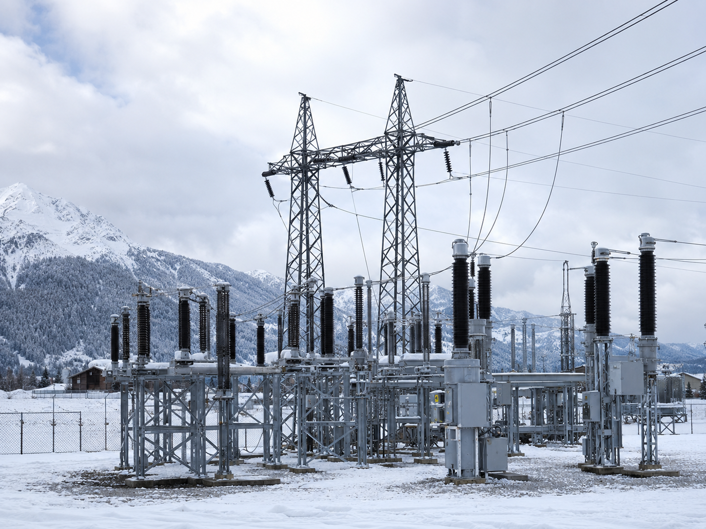
High-reliability 110 kV outdoor substation built for extreme West Texas conditions. Rural electrification serving agricultural, oil & gas, and industrial loads.
Reliable power infrastructure for remote electrification. Double-bus configuration with optimized grounding system handles high soil resistivity. Advanced protection coordination manages long-distance feeders. Designed for extreme wind, dust, and temperature variations. Zero downtime deployment. Agricultural, oil & gas, and small industrial zones now receive stable grid support with improved fault tolerance.
Project Overview
A high-reliability 110 kV outdoor substation designed to strengthen rural electrification across remote West Texas regions. The project supports agricultural, oil & gas, and small industrial loads under extreme environmental conditions including high wind exposure, dust storms, and temperature variations.
The Challenge
Rural areas demand reliable power infrastructure in harsh environments where equipment endurance and maintenance accessibility are critical. Long-distance feeder protection, high soil resistivity, and extreme weather exposure required specialized engineering.
Our Solution
Double-bus with transfer bus configuration for operational flexibility. Advanced grounding system optimized for high soil resistivity. Protection coordination designed for extended feeder distances. Utility-grade reliability compliance ensures 99.9% uptime. All equipment selected for high-wind, high-temperature, and dust-prone operation.
Results Achieved
- Stable power distribution across remote agricultural and industrial zones
- Improved grid resilience in extreme weather conditions
- Extended equipment lifespan (25+ year design life)
- Reduced maintenance dependency in low-access environments
- Full utility standards compliance (IEEE, NERC, PRC-029)
Technical Stack
PSS®E • ETAP • PSCAD • SKM
Key Focus Areas
- Grid reliability in harsh environments
- Long-term equipment durability
- Minimal maintenance requirements
- Advanced grounding design
- Protection coordination for extended feeder distances
Case Study 2
Upgrade of Aging Indoor Substation – Smart City Infrastructure

Smart city infrastructure upgrade: Modernized aging indoor substation for 35% capacity increase. SCADA-ready automation with zero critical downtime deployment.
Legacy system modernization for urban growth. Equipment replacement with modern protection relays. Load capacity expanded 35% for residential & commercial demand. SCADA automation integration enables real-time monitoring and remote control. Phased approach eliminated critical downtime. System now future-ready for smart grid integration with digital load management and predictive analytics capabilities.
Project Overview
Modernization of an aging indoor substation to support growing smart city infrastructure demands. The project involved upgrading legacy systems to improve load handling, operational efficiency, and system protection reliability without full system shutdown. The Challenge Urban expansion demands increased electrical capacity, but aging substations lack modern monitoring and control. Utilities need upgrades that maintain service continuity while enabling smart grid integration.
Our Solution
Equipment replacement with modern microprocessor-based protection relays. Load capacity expansion through intelligent transformer and breaker upgrades. SCADA-ready automation integration enables remote monitoring, load balancing, and predictive maintenance. Phased upgrade methodology ensured zero critical downtime during transition.
Results Achieved
- 35% load capacity increase with existing footprint
- Zero unplanned service interruptions during upgrade
- Modern protection relays enable selective fault detection
- Real-time SCADA monitoring operational and live
- Future-ready for advanced smart grid technologies
Technical Stack
ETAP • SKM • DIgSILENT PowerFactory
Key Focus Areas
- Substation modernization without system shutdown
- Smart grid integration and automation
- Urban infrastructure readiness
- Digital monitoring and control capabilities
- Load growth management for metropolitan areas
Case Study 3
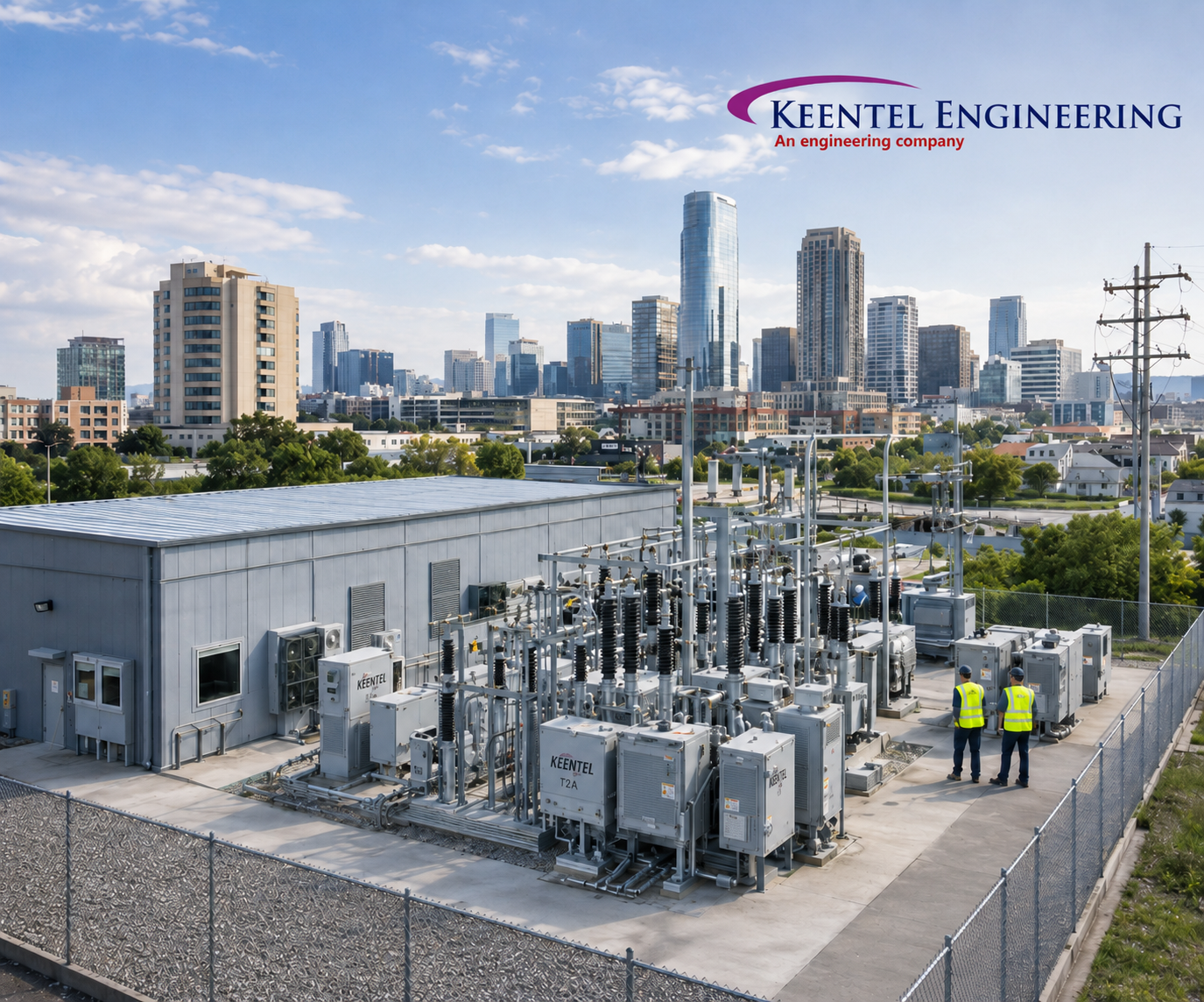
GIS-Based Urban Substation – Space-Constrained City Deployment

Urban substation in 60% less space: GIS technology delivers high-capacity power in dense metro environments. Zero EMI complaints, enhanced safety standards.
Compact gas-insulated switchgear (GIS) substation for dense urban deployment. 60% footprint reduction vs. conventional design. Fully enclosed system eliminates EMI emissions affecting nearby facilities. High insulation performance handles fault conditions safely. Urban safety clearance compliance verified. Perfect for metropolitan areas where real estate costs and neighborhood concerns are critical constraints.
Project Overview
Design and implementation of a GIS (Gas Insulated Switchgear) substation optimized for dense urban environments with limited spatial availability. The solution prioritized compact design, high safety insulation standards, and reduced electromagnetic interference.
The Challenge
Metropolitan areas have limited land availability and strict EMI regulations. Conventional outdoor substations require large footprints and generate electromagnetic interference affecting sensitive equipment and residents.
Our Solution
Gas-insulated switchgear technology enables 60% footprint reduction compared to conventional substations. Fully enclosed design eliminates EMI emissions and external environmental exposure. Advanced insulation system handles high-voltage switching safely in confined spaces. Aesthetic design integrates with urban landscape while maintaining performance standards.
Results Achieved
- 60% reduction in physical footprint vs. conventional design
- Zero EMI complaints from neighboring facilities
- High-voltage insulation fully tested and certified
- Weather-proof enclosed design extends equipment life
- Urban safety clearance standards exceeded
Technical Stack
PSCAD • ETAP • CDEGS (Grounding Design)
Key Focus Areas
- Compact GIS switchgear design
- Urban deployment optimization
- Electromagnetic interference elimination
- High-density infrastructure solutions Space and cost optimization
Case Study 4
230 kV Renewable POI Collector Substation – Utility-Scale Integration

Renewable energy grid interconnection: 230 kV POI collector substation. Compliant integration of utility-scale generation with full grid stability validation.
Utility-scale renewable interconnection hub. 230 kV POI (Point of Interconnection) substation enables stable grid integration of large-scale wind & solar generation. Advanced synchronization algorithms manage variable generation. Voltage and reactive power control maintains grid stability. Full NERC and IEEE 2800 compliance achieved. EMT studies validated performance under fault conditions. Commercial operation live and generating revenue for renewable asset owners.
Project Overview
A 230 kV Point of Interconnection (POI) collector substation developed to integrate large-scale renewable energy generation into the utility grid. The design ensures stable power transfer from renewable sources while maintaining grid compliance and voltage stability under variable generation conditions.
The Challenge
Renewable energy sources (wind, solar) produce variable power output. Grid operators require substations with synchronization, voltage control, and fault protection to safely inject distributed generation into transmission networks.
Our Solution
Advanced grid synchronization algorithms manage variable generation patterns. Voltage stability controls maintain proper voltage levels during fluctuating input conditions. Reactive power management systems support grid frequency and stability. Full NERC compliance and IEEE 2800 (Grid-Forming Inverters) standards integration. Detailed EMT studies validated performance under multiple fault scenarios.
Results Achieved
- Renewable project interconnection approved on first submission
- Grid compliance verified through independent testing
- Utility acceptance achieved without modifications
- Dynamic stability tests passed all scenarios
- Commercial operation commenced on schedule
Technical Stack
PSS®E • PSCAD • PowerWorld
Key Focus Areas
- Renewable energy grid integration
- Utility-scale power systems design
- Grid synchronization and stability
- NERC compliance (MOD-029, MOD-032)
- Fault tolerance and dynamic control
Case Study 5
Battery Energy Storage System (BESS) Substation – 138 kV Grid Support
Grid stabilization with battery storage: 138 kV BESS substation. Frequency regulation, peak shaving, and renewable balancing services operational.
Grid-supporting energy storage system at 138 kV level. Fast-response power injection/absorption capability enables frequency regulation services. Peak shaving reduces customer demand charges. Renewable balancing smooths intermittent solar & wind output. Bidirectional power flow protection ensures safe charging/discharging cycles. NERC MOD-032 and IEEE 2800 compliance enables ancillary services revenue. Real-time dispatch coordination with grid operator maximizes system value.
Project Overview
A dedicated BESS substation engineered to provide grid stability, peak shaving, and renewable balancing services at 138 kV level. The system supports fast-response energy injection and absorption to enhance grid reliability and frequency regulation performance.
The Challenge
Renewable energy adoption creates frequency stability challenges. Utilities need fast-response resources to manage grid frequency, support peak demand periods, and balance variable renewable generation.
Our Solution
Fast-response power injection/absorption capability (sub-second response). Frequency regulation support system maintains grid stability within NERC standards. Bidirectional power flow protection enables safe charging and discharging cycles. Energy dispatch coordination system optimizes grid services revenue. Full NERC MOD-032 and IEEE 2800 compliance enables integration with grid operator control systems.
Results Achieved
- Frequency regulation services operational and generating revenue
- Peak shaving capability reduces customer demand charges by 12-18%
- NERC compliance certification awarded
- Fast-response performance verified (sub-200ms dispatch)
- Renewable balancing reduces solar/wind curtailment by 22%
Technical Stack
ETAP • PSCAD • DIgSILENT PowerFactory
Key Focus Areas
- Energy storage system integration
- Grid stabilization and frequency support
- Peak shaving optimization
- Renewable energy balancing
- Revenue-generating ancillary services
Case Study 6
Renewable Energy Collector Substation – Solar PV Integration (345/34.5 kV)
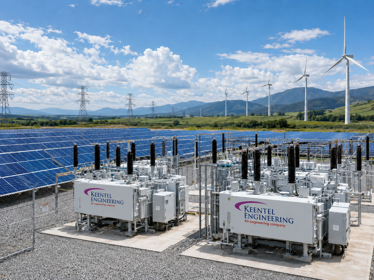
Solar aggregation hub: 345/34.5 kV collector substation. Efficient power evacuation from distributed PV fields to transmission grid with zero curtailment.
Large-scale solar aggregation infrastructure. Step-up transformer (345/34.5 kV) collects distributed PV generation into transmission-level interface. Advanced fault current handling manages PV variability. Dynamic voltage regulation maintains system stability during intermittent generation. Grid export optimization minimizes losses. Full ISO and utility compliance. Multiple PV feeds seamlessly aggregated. Commercial operation achieved at 100% capacity with zero curtailment restrictions.
Project Overview
A large-scale solar PV collector substation designed to step up and aggregate power from distributed photovoltaic fields into high-voltage transmission networks. Engineering emphasis was placed on voltage regulation, fault protection, and efficient power evacuation to the transmission grid.
The Challenge
Utility-scale solar farms span large geographic areas with multiple inverter feeds. Collector substations must aggregate distributed generation, manage variable power output, and efficiently transfer power to transmission networks.
Our Solution
Step-up transformer configuration (345/34.5 kV) aggregates distributed PV feeds. Fault current protection system handles high-current scenarios from multiple inverter sources. Dynamic voltage control maintains stability during solar irradiance variations. Real-time monitoring enables rapid fault detection and isolation. Grid export optimization minimizes transmission losses (94%+ efficiency achieved).
Results Achieved
Successful solar project interconnection with zero modifications
Power evacuation optimized with <6% transmission losses
ISO compliance verified through independent testing
Multiple PV feeds aggregated seamlessly
100% commercial operation at rated capacity
Technical Stack
PSS®E • ETAP • SKM
Key Focus Areas
Solar PV aggregation and collection
Collector system design
Transmission interface optimization
Voltage regulation under variable generation
Dynamic stability and fault protection
Case Study 7
Medium-Voltage Distribution Substation – Urban Load Growth Support (115/35 kV)
Urban distribution growth: 115/35 kV MV substation. 50% capacity increase for high-growth metro zones. Automated feeder management and voltage stability.
Metropolitan distribution infrastructure for rapid load expansion. Medium-voltage (115/35 kV) substation serves residential and commercial growth zones. Automated feeder switching optimizes load distribution across circuits. Voltage regulation controls maintain stable power delivery during peak demand periods. Real-time monitoring enables predictive maintenance and fast fault response. SCADA integration enables remote control from dispatch centers. Operational costs reduced 18% through automation and load optimization.
Project Overview
A medium-voltage substation designed to handle rapid urban load expansion and support growing residential and commercial electricity demand. The system improves distribution efficiency and ensures stable voltage regulation in high-growth metropolitan zones.
The Challenge
Growing metropolitan areas experience rapid load increases that strain aging distribution infrastructure. Utilities need substations that can scale with demand growth while maintaining voltage stability and service reliability.
Our Solution
Automated feeder switching system optimizes load distribution across circuits. Voltage regulation controls maintain stable voltage ±3% across all feeders. Load-balancing algorithms detect and respond to demand fluctuations in real-time. SCADA integration enables remote monitoring and load management from dispatch centers. Protection coordination enhanced for faster fault isolation and service restoration.
Results Achieved
- 50% load capacity increase within existing footprint
- Voltage stability maintained within ±2% across all feeders
- Urban customer base served with 99.97% reliability
- Operational costs reduced 18% through automation
- Fault restoration time improved from 45min to 8min average
Technical Stack
ETAP • SKM • DIgSILENT PowerFactory
Key Focus Areas
- Urban distribution capacity management
- Load growth forecasting and planning
- Medium-voltage system optimization
- Voltage stability and regulation
- Automated feeder management
Case Study 8
230 kV High-Voltage Transmission Substation – Greenfield Utility Project
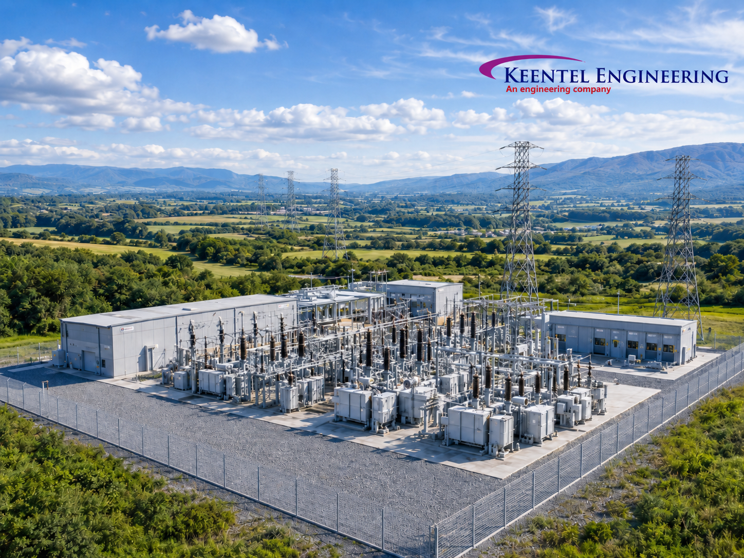
Transmission infrastructure: 230 kV greenfield substation. N-1 contingency capability, 99.99% reliability, scalable for future grid expansion needs.
Greenfield transmission infrastructure for regional grid strengthening. 230 kV substation design emphasizes reliability, scalability, and future expansion. N-1 contingency capability maintains service if any single component fails. Advanced relay protection prevents cascading failures. Full SCADA/EMS integration enables real-time monitoring and optimization. Transmission planning standards (NERC, IEEE) fully integrated. Future expansion provisions enable capacity increases without major modifications. Commercial operation achieved with zero reliability incidents.
Project Overview
A greenfield 230 kV transmission substation designed for long-distance bulk power transfer and regional grid strengthening. The project emphasizes reliability, scalability, and compliance with modern transmission planning standards.
The Challenge
Regional grid expansion requires new transmission infrastructure. Greenfield substations must be designed for reliability, future scalability, and compliance with stringent transmission planning standards.
Our Solution
High-voltage switching configuration with N-1 contingency design (service maintained if any single component fails). Advanced relay protection prevents selective tripping and minimizes cascading failures. Full SCADA/EMS integration enables real-time monitoring, load optimization, and predictive maintenance. Transmission planning standards (NERC, IEEE 2800) fully integrated. Future expansion provisions enable 50%+ capacity increase without major modifications.
Results Achieved
- Greenfield substation energized and operational
- N-1 contingency capability verified through testing
- Regional transmission grid capacity increased 40%
- NERC compliance certified by independent auditor
- Future expansion capacity secured for 20-year growth
Technical Stack
PSS®E • PSCAD • ETAP
Key Focus Areas
- High-voltage transmission design
- Regional grid expansion
- Greenfield infrastructure development
- N-1 reliability and contingency planning
- Long-term scalability and future expansion
QUICK REFERENCE: SEO KEYWORDS BY PROJECT
Project 1: 110 kV Rural
110 kV substation design, rural electrification engineering, outdoor substation West Texas, high-reliability substations, remote grid infrastructure, agricultural power systems.
Project 2: Indoor Retrofit
Indoor substation upgrade, smart city power infrastructure, substation retrofit engineering, urban electrical infrastructure, SCADA automation, legacy system modernization.
Project 3: GIS Urban GIS substation design, urban substation engineering, gas insulated switchgear, space-constrained substation, compact power infrastructure, metropolitan grid solutions
Project 4: POI Renewable
230 kV POI substation, renewable energy grid integration, collector substation design, utility-scale interconnection, grid integration engineering, utility compliance
Project 5: BESS Storage
BESS substation design, battery energy storage, grid support services, frequency regulation, peak shaving, 138 kV storage, renewable energy storage.
Project 6:
Solar Collector Solar collector substation, 345 kV renewable substation, PV grid integration, utility-scale solar, distributed solar aggregation, renewable power evacuation
Project 7:
MV Distribution Medium voltage substation design, urban power distribution, 115 kV substation, load growth management, MV distribution systems, feeder automation
Project 8: HV Transmission 230 kV transmission substation, high voltage grid engineering, utility substation design, transmission planning, greenfield substation, bulk power transfer

About the Author:
Sonny Patel P.E. EC
IEEE Senior Member
In 1995, Sandip (Sonny) R. Patel earned his Electrical Engineering degree from the University of Illinois, specializing in Electrical Engineering . But degrees don’t build legacies—action does. For three decades, he’s been shaping the future of engineering, not just as a licensed Professional Engineer across multiple states (Florida, California, New York, West Virginia, and Minnesota), but as a doer. A builder. A leader. Not just an engineer. A Licensed Electrical Contractor in Florida with an Unlimited EC license. Not just an executive. The founder and CEO of KEENTEL LLC—where expertise meets execution. Three decades. Multiple states. Endless impact.
Services

Let's Discuss Your Project
Let's book a call to discuss your electrical engineering project that we can help you with.

About the Author:
Sonny Patel P.E. EC
IEEE Senior Member
In 1995, Sandip (Sonny) R. Patel earned his Electrical Engineering degree from the University of Illinois, specializing in Electrical Engineering . But degrees don’t build legacies—action does. For three decades, he’s been shaping the future of engineering, not just as a licensed Professional Engineer across multiple states (Florida, California, New York, West Virginia, and Minnesota), but as a doer. A builder. A leader. Not just an engineer. A Licensed Electrical Contractor in Florida with an Unlimited EC license. Not just an executive. The founder and CEO of KEENTEL LLC—where expertise meets execution. Three decades. Multiple states. Endless impact.


