
A Coordinated Electric System Interconnection Review—the utility’s deep-dive on technical and cost impacts of your project.
Challenge: Frequent false tripping using conventional electromechanical relays
Solution: SEL-487E integration with multi-terminal differential protection and dynamic inrush restraint
Result: 90% reduction in false trips, saving over $250,000 in downtime
ERCOT enforces all of the above through simulation, which means your model is your compliance case. The bar is now high:
- Whole-facility scope. The model must represent everything the IT load, the UPS and power conversion, the cooling plant, the protection and control systems in formats compatible with ERCOT's study platforms (PSS/E, PSCAD, TSAT).
- Real control loops, not approximations. Generic textbook representations are unacceptable. The model must capture the actual inner control behavior of your power electronics.
- Hardware-validated converter models. For electronic loads, the PSCAD model must be benchmarked against actual hardware testing including voltage ride-through and subsynchronous response. A model assembled from standard PSCAD library blocks fails by definition, because a generic block has never been tested against your vendor's hardware. The good news: validation is a hardware-type test, so results for a given converter product are reusable across every facility that uses it.
- Format migration. Facilities that previously submitted the older composite load model (CMLD) format must transition to EPRI's PERC1 format.
- Three checkpoints. Models are reviewed before the stability study begins (no model, no study), before each quarterly stability assessment, and for electronic loads one final time before energization, when you must submit as-built models with a documented comparison against the previously studied data and a sworn attestation that the model matches actual field settings. ERCOT's review takes 10 business days, extendable by 20 put it on your critical path.
- A living obligation. Change your technology, controls, or relay settings in a way that affects ride-through including converting a crypto mining site to an AI data center — and you've triggered a new interconnection study, even if your megawatts don't change.
| Parameter | Detail |
|---|---|
| System | 230 kV / 138 kV transmission corridors, wind and wet-snow icing exposure |
| Data basis | 15 years of minute-resolution forced-outage records + regional weather observations |
| Core methods | Event grouping, MVA performance curves, time-to-95%-restore, area outage rate curves, fragility modeling, rerun-history benefits, exceedance and log-domain risk metrics |
| Headline result | ≈85% of maximum resilience benefit at 60% of original capital; worst-event restoration window cut from 11 days to 5 in rerun-history terms |
| Decision supported | Capital portfolio selection; resilience plan filing; post-investment verification framework |
| System / Topic | Governing Standard(s) | What It Controls |
|---|---|---|
| Overall plant electrical distribution | IEEE 141 (Red Book); IEEE 666 | Distribution architecture, voltage selection, design of generating station auxiliary service systems |
| Power system studies | IEEE 399 (Brown Book); IEEE 551 | Load flow, symmetrical/asymmetrical short circuit, motor starting methodologies down to the lowest LV panelboard |
| Protection & coordination | IEEE 242 (Buff Book); IEEE 3004.5; IEEE C37 series | Generator relaying (21, 59N, 87G), time-current coordination, selective clearing between LV and MV tiers |
| GSU / UAT / SST transformers | IEEE C57.12.00 and C57 family | Transformer ratings, impedance, testing, loading |
| HV switchyard breakers | IEEE C37.06 | AC high-voltage circuit breaker preferred ratings |
| MV switchgear (13.8 kV) | IEEE C37.20.2; IEEE C37.20.7 | Metal-clad construction, compartmentalization, vacuum breakers; arc-resistant design with plenum venting |
| MV cable | UL 1072; ICEA S-93-639 (NEMA WC 74) | Type MV-105 shielded cable, 133% insulation level for HRG systems |
| LV switchgear (480 V) | IEEE C37.13; UL 1558 | Metal-enclosed LV power circuit breaker switchgear to 635 V, draw-out ACBs with electronic trip units |
| Motor control centers | UL 845; NEMA ICS 18 | LV-MCC construction, MCCB/MCP protection for motors under ~200 HP |
| Motors | NEMA MG-1 | Motor performance, starting characteristics, service factors |
| DC & battery systems | IEEE 485; IEEE 946 | Lead-acid battery sizing (125/250 VDC), DC auxiliary system design |
| Grounding | IEEE 80; IEEE 142 (Green Book) | Ground grid step/touch potential limits; system grounding including high-resistance grounding |
| Lightning protection | IEEE 998 | Direct-stroke shielding of switchyard and outdoor generator structures |
| Arc flash & electrical safety | IEEE 1584; NFPA 70E | Incident energy calculation; worker safety boundaries and PPE |
| Fire protection | NFPA 850 | Fire protection and risk management for combustion turbine generating plants |
| Installation code | NEC (NFPA 70); NESC | Wiring methods inside the plant fence; overhead/outdoor clearances at the switchyard |
| Interconnection & compliance | FERC LGIP; NERC MOD-025/026/027, PRC-019/024/029, FAC-008 | Interconnection process, model validation, protection/ride-through coordination, facility ratings |
| IFC / Construction Deliverable | Purpose |
|---|---|
| Stamped IFC packages | Legal basis for construction; P.E. responsible charge |
| Final relay settings & TCCs | Protection as-installed matches the coordination study |
| Calculation archive | Owner records; NERC audit evidence trail |
| Commissioning procedures | Safe, sequenced energization; MOD field testing |
| Construction support | RFIs, field changes, FAT/SAT witness |
| As-builts & model handoff | Operating baseline; future study currency |
| Metric | Outcome |
|---|---|
| Defects found pre-occupancy | Three topology defects and one settings-mismatch family corrected before load migration; the shared-switchboard defect alone would have invalidated the concurrently-maintainable claim on day one |
| IST findings | Fourteen additional discrepancies surfaced under scenario testing (control logic, alarm mapping, one generator sequencing fault) — all closed before handover instead of during operations |
| Black-building test | Passed on second execution; the first attempt exposed the generator sequencing fault under true block load, exactly the failure the compressed plan would never have found |
| Handover quality | Operations team certified on the actual failure scenarios; corrected EOPs and settings documentation delivered as controlled documents |
| Business outcome | Occupancy proceeded three weeks behind the original date — against an independent estimate that the uncorrected sequencing fault carried a high probability of a full facility outage within the first year |
Part 2 — Frequently Asked Questions: Large Load Interconnection
| Contact | Details |
|---|---|
| Headquarters | 400 N Ashley Dr STE 2600, Tampa, FL 33602 |
| Phone | (813) 389-7871 |
| contact@keentelengineering.com | |
| Florida Firm Registration | No. 36853 |
| Additional Offices | Austin, TX • Sacramento, CA • Baltimore, MD |
| Who | Acronym | Plain-English Role |
|---|---|---|
| ERCOT | — | The grid's air traffic controller. It doesn't own power lines or plants; it directs the flow of electricity across most of Texas and referees the admission process for new generators. |
| Interconnecting Entity | IE | You — the developer or owner trying to connect a new plant (or significantly modify an existing one). You file the application and drive the process. |
| Resource Entity | RE | The registered owner/operator of the generator once it becomes an official market participant. Often the same company as the IE, wearing a different hat. |
| Qualified Scheduling Entity | QSE | Your plant's voice on the grid. The QSE handles round-the-clock communications with ERCOT — telemetry, schedules, dispatch instructions. Every generator must have one. |
| Transmission Service Provider | TSP | The utility that owns the wires and substation you'll connect to. The TSP runs your detailed study, builds the connection facilities, and signs your interconnection contract. |
| RIOO-IS | — | ERCOT's online portal where the whole process lives — applications, documents, status tracking, and checklists all flow through it. |
| Who | Acronym | Plain-English Role |
|---|---|---|
| ERCOT | — | The grid's air traffic controller. It doesn't own power lines or plants; it directs the flow of electricity across most of Texas and referees the admission process for new generators. |
| Interconnecting Entity | IE | You — the developer or owner trying to connect a new plant (or significantly modify an existing one). You file the application and drive the process. |
| Resource Entity | RE | The registered owner/operator of the generator once it becomes an official market participant. Often the same company as the IE, wearing a different hat. |
| Qualified Scheduling Entity | QSE | Your plant's voice on the grid. The QSE handles round-the-clock communications with ERCOT — telemetry, schedules, dispatch instructions. Every generator must have one. |
| Transmission Service Provider | TSP | The utility that owns the wires and substation you'll connect to. The TSP runs your detailed study, builds the connection facilities, and signs your interconnection contract. |
| RIOO-IS | — | ERCOT's online portal where the whole process lives — applications, documents, status tracking, and checklists all flow through it. |
| Who | Acronym | Plain-English Role |
|---|---|---|
| ERCOT | — | The grid's air traffic controller. It doesn't own power lines or plants; it directs the flow of electricity across most of Texas and referees the admission process for new generators. |
| Interconnecting Entity | IE | You — the developer or owner trying to connect a new plant (or significantly modify an existing one). You file the application and drive the process. |
| Resource Entity | RE | The registered owner/operator of the generator once it becomes an official market participant. Often the same company as the IE, wearing a different hat. |
| Qualified Scheduling Entity | QSE | Your plant's voice on the grid. The QSE handles round-the-clock communications with ERCOT — telemetry, schedules, dispatch instructions. Every generator must have one. |
| Transmission Service Provider | TSP | The utility that owns the wires and substation you'll connect to. The TSP runs your detailed study, builds the connection facilities, and signs your interconnection contract. |
| RIOO-IS | — | ERCOT's online portal where the whole process lives — applications, documents, status tracking, and checklists all flow through it. |
| Who | Acronym | Plain-English Role |
|---|---|---|
| ERCOT | — | The grid's air traffic controller. It doesn't own power lines or plants; it directs the flow of electricity across most of Texas and referees the admission process for new generators. |
| Interconnecting Entity | IE | You — the developer or owner trying to connect a new plant (or significantly modify an existing one). You file the application and drive the process. |
| Resource Entity | RE | The registered owner/operator of the generator once it becomes an official market participant. Often the same company as the IE, wearing a different hat. |
| Qualified Scheduling Entity | QSE | Your plant's voice on the grid. The QSE handles round-the-clock communications with ERCOT — telemetry, schedules, dispatch instructions. Every generator must have one. |
| Transmission Service Provider | TSP | The utility that owns the wires and substation you'll connect to. The TSP runs your detailed study, builds the connection facilities, and signs your interconnection contract. |
| RIOO-IS | — | ERCOT's online portal where the whole process lives — applications, documents, status tracking, and checklists all flow through it. |
| Who | Acronym | Plain-English Role |
|---|---|---|
| ERCOT | — | The grid's air traffic controller. It doesn't own power lines or plants; it directs the flow of electricity across most of Texas and referees the admission process for new generators. |
| Interconnecting Entity | IE | You — the developer or owner trying to connect a new plant (or significantly modify an existing one). You file the application and drive the process. |
| Resource Entity | RE | The registered owner/operator of the generator once it becomes an official market participant. Often the same company as the IE, wearing a different hat. |
| Qualified Scheduling Entity | QSE | Your plant's voice on the grid. The QSE handles round-the-clock communications with ERCOT — telemetry, schedules, dispatch instructions. Every generator must have one. |
| Transmission Service Provider | TSP | The utility that owns the wires and substation you'll connect to. The TSP runs your detailed study, builds the connection facilities, and signs your interconnection contract. |
| RIOO-IS | — | ERCOT's online portal where the whole process lives — applications, documents, status tracking, and checklists all flow through it. |
| Who | Acronym | Plain-English Role |
|---|---|---|
| ERCOT | — | The grid's air traffic controller. It doesn't own power lines or plants; it directs the flow of electricity across most of Texas and referees the admission process for new generators. |
| Interconnecting Entity | IE | You — the developer or owner trying to connect a new plant (or significantly modify an existing one). You file the application and drive the process. |
| Resource Entity | RE | The registered owner/operator of the generator once it becomes an official market participant. Often the same company as the IE, wearing a different hat. |
| Qualified Scheduling Entity | QSE | Your plant's voice on the grid. The QSE handles round-the-clock communications with ERCOT — telemetry, schedules, dispatch instructions. Every generator must have one. |
| Transmission Service Provider | TSP | The utility that owns the wires and substation you'll connect to. The TSP runs your detailed study, builds the connection facilities, and signs your interconnection contract. |
| RIOO-IS | — | ERCOT's online portal where the whole process lives — applications, documents, status tracking, and checklists all flow through it. |
| Who | Acronym | Plain-English Role |
|---|---|---|
| ERCOT | — | The grid's air traffic controller. It doesn't own power lines or plants; it directs the flow of electricity across most of Texas and referees the admission process for new generators. |
| Interconnecting Entity | IE | You — the developer or owner trying to connect a new plant (or significantly modify an existing one). You file the application and drive the process. |
| Resource Entity | RE | The registered owner/operator of the generator once it becomes an official market participant. Often the same company as the IE, wearing a different hat. |
| Qualified Scheduling Entity | QSE | Your plant's voice on the grid. The QSE handles round-the-clock communications with ERCOT — telemetry, schedules, dispatch instructions. Every generator must have one. |
| Transmission Service Provider | TSP | The utility that owns the wires and substation you'll connect to. The TSP runs your detailed study, builds the connection facilities, and signs your interconnection contract. |
| RIOO-IS | — | ERCOT's online portal where the whole process lives — applications, documents, status tracking, and checklists all flow through it. |
Protection Design
New Title
New Paragraph
FAC-008-5 Facility Ratings
Aug 11, 2026 | Blog
Building an Audit-Ready Engineering, Evidence, and Data Governance Program
An in-depth technical blog, compliance FAQ, and three anonymized composite case studies for Transmission Owners and Generator Owners
1: Executive Overview
FAC-008-5 - Facility Ratings is a core engineering governance standard for the reliable planning and operation of the Bulk Electric System. It applies to Generator Owners and Transmission Owners and is built around a simple but demanding principle: a Facility Rating must not exceed the most limiting applicable Equipment Rating of the equipment that comprises the Facility.
That principle sounds straightforward until it is applied across a real asset portfolio. A single Facility can include conductors, transformers, current transformers, circuit breakers, disconnect switches, wave traps, primary fuses, relay protective devices, terminal equipment, and compensation devices. The rating program must account for ownership boundaries, normal and emergency operating states, ambient conditions, temporary derates, field configuration, joint ownership, and the exact values used in planning and operations systems.
FAC-008-5 therefore operates as three connected control layers. Requirements R1, R2, and R3 establish the technical basis and documented methodology. Requirement R6 tests whether actual Facility Ratings remain consistent with that basis. Requirement R8 tests whether required rating and limiting-equipment information is provided to the appropriate reliability entities on the required schedule. Weakness in any layer can create audit exposure even when individual rating calculations appear technically reasonable.
Keentel Engineering supports registered entities by combining electrical engineering expertise, NERC compliance program design, audit-readiness services, and configurable compliance software. The objective is not merely to prepare a document for an audit. The objective is to build a sustainable Facility Ratings control environment in which rating decisions are reproducible, changes are governed, evidence is retained, and compliance information can be produced efficiently.
The audit-ready standard of performance
An auditor should be able to select a Facility, identify its ownership and rating boundary, trace the Facility Rating to each applicable Equipment Rating, confirm the limiting component, verify the values implemented in relevant systems, review approvals and changes, and locate any required R8 communications without relying on undocumented institutional knowledge.
2: Understanding FAC-008-5 and Why Facility Ratings Programs Fail
2.1: What FAC-008-5 is designed to accomplish
The stated purpose of FAC-008-5 is to ensure that Facility Ratings used in reliable BES planning and operation are determined using technically sound principles. Facility Ratings are essential inputs to System Operating Limits and influence transfer capability, outage analysis, generator deliverability, congestion management, and operating decisions.
The standard does not impose one universal calculation formula. For R2 and R3, the rating methodology may be based on manufacturer ratings or specifications, an industry standard developed through an open process, or a practice verified by testing, performance history, or engineering analysis. The entity must document the basis it uses and explain how standards, manufacturer information, ambient conditions, and operating limitations are considered.
2.2: Equipment Rating versus Facility Rating
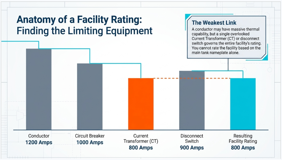
An Equipment Rating describes the capability or operating limit of an individual component. A Facility Rating is the capability assigned to the Facility as a whole. The Facility Rating is constrained by the most limiting applicable component in the relevant electrical path and operating condition.
A conductor may have a higher thermal capability than the circuit breaker connected to it. A transformer may have a strong nameplate rating while a bushing, current transformer, disconnect switch, wave trap, or protection-related loadability limit is lower. A compliant process identifies the applicable equipment, determines valid Equipment Ratings, compares those ratings under the relevant normal or emergency condition, and assigns a Facility Rating that respects the limiting value.
2.3: Why rating programs fail despite having calculations
1: The methodology is incomplete and does not cover every equipment type that could limit the Facility
2: Ownership boundaries are unclear, particularly around the main step-up transformer, jointly owned switchyards, and interconnection equipment
3: The engineering method is documented, but the values loaded into EMS, planning, outage, or asset systems do not match the approved calculations
4: Normal and Emergency Ratings are stored as values without separately documented assumptions, durations, or calculation methods
5: Temporary derates are communicated operationally but are not consistently controlled, approved, retained, or reconciled
6: Terminal equipment and current transformers are excluded because the organization historically focused on conductors and transformers
7: R8 requests are handled through individual email accounts without a centralized due-date, response, or evidence-retention process
8: The entity cannot reconstruct why a rating changed, who approved it, or which systems were updated
Keentel Engineering perspective
The most effective FAC-008-5 programs treat Facility Ratings as a controlled engineering data lifecycle, not as a collection of calculation spreadsheets. The lifecycle begins with ownership and asset scope, continues through engineering determination and approval, and ends with implementation, communication, monitoring, and retained evidence.
3: Regulatory and Implementation Context
3.1: Transition from FAC-008-3 to FAC-008-5
FAC-008-5 resulted from the NERC Standards Efficiency Review effort. An earlier proposal would have retired both R7 and R8. FERC concluded that retirement of R7 would not create a reliability gap, but rejected retirement of R8 because identification and communication of limiting and next limiting equipment remained necessary for reliability. FAC-008-5 therefore retired R7 while retaining the R8 information-sharing obligations.
The implementation plan established a jurisdiction-specific transition in which FAC-008-5 would become effective on the first day of the first calendar quarter that is three months after applicable approval, unless an applicable authority provided otherwise. FAC-008-3 would retire immediately before FAC-008-5 became effective in the relevant jurisdiction.
3.2: Why the regulatory history matters to compliance teams
The regulatory history is important because it shows that R8 is not a minor administrative reporting provision. It is a reliability control intended to provide planners and operators with visibility into the current limiting equipment and the next constraint that would govern if the present bottleneck were removed or rerated.
For practical compliance, a registered entity should be able to determine whether an R8 request triggers only the scheduled information in R8.1 or also the 30-calendar-day next-limiting-equipment information in R8.2. The response process must connect compliance personnel, facility-rating engineers, asset data owners, planning personnel, and records management.
3.3: The RSAW as an audit lens
The FAC-008-5 RSAW converts the standard into an audit assessment workflow. It asks the entity to identify subject matter experts, provide a narrative compliance explanation, list evidence with document-level detail, and respond to requirement-specific applicability questions. The auditor sections emphasize clear assumptions, methodology completeness, limiting-equipment treatment, facility lists for sampling, and dated evidence of R8 requests and responses.
The RSAW also gives practical interpretation to equipment scope. For R2 and R3, the auditor note identifies wave traps, current transformers, disconnect switches, breakers, primary fuses, and any series-connected equipment that could have the most limiting rating as terminal equipment that should be addressed when owned by the entity.
Source basis: FAC-008-5 version history and requirements; Project 2018-03 Implementation Plan; FAC-008-5 RSAW regulatory language and audit approach.
4:The FAC-008-5 Compliance Operating Model
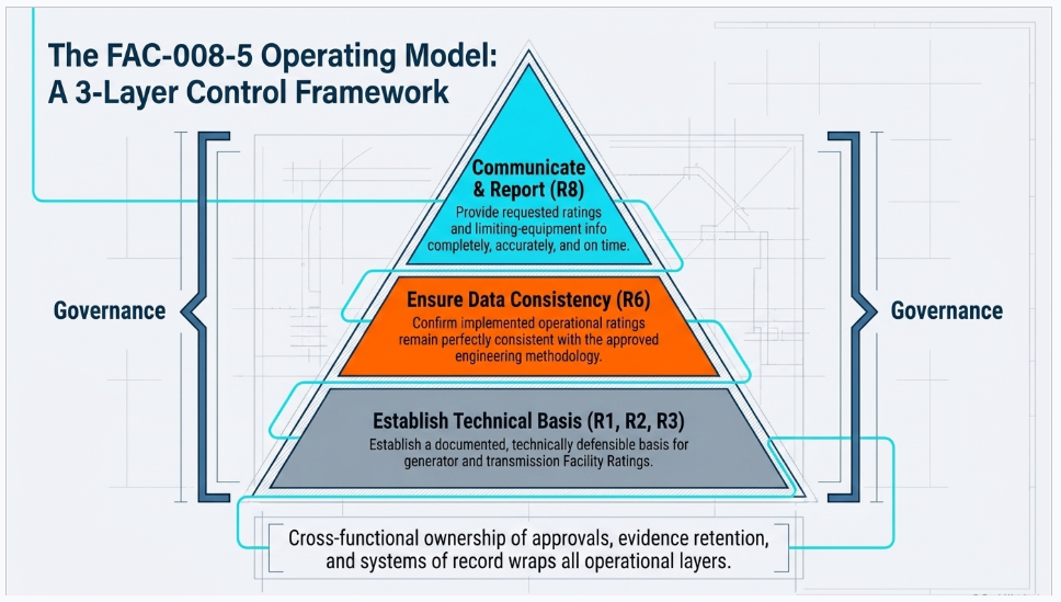
A sustainable FAC-008-5 program can be organized into three control layers supported by common governance. This model helps engineering, operations, planning, compliance, and information technology teams understand how their responsibilities connect.
| Control layer | Primary requirements | Core compliance objective |
|---|---|---|
| 1 | R1, R2, R3 | Establish a documented and technically defensible basis for generator and transmission Facility Ratings |
| 2 | R6 | Confirm that implemented ratings remain consistent with the approved documentation and methodology |
| 3 | R8 | Provide requested ratings and limiting-equipment information completely, accurately, and on time |
| Across all layers | Governance | Control ownership, approvals, changes, evidence, retention, joint ownership, and system-of-record responsibilities |
4.1: Requirement applicability and risk map
| Req | Applicable function | VRF / time horizon | Primary obligation |
|---|---|---|---|
| R1 | GO | Lower / Long-term Planning | Maintain generator Facility Rating documentation through the applicable GSU boundary |
| R2 | GO | Medium / Long-term Planning | Maintain a methodology for GO-owned equipment between the R1 boundary and the TO interconnection |
| R3 | TO | Medium / Long-term Planning | Maintain a methodology for solely and jointly owned transmission Facilities |
| R4 | Reserved | Reserved | No active compliance obligation |
| R5 | Reserved | Reserved | No active compliance obligation |
| R6 | GO and TO | Medium / Operations Planning | Maintain Facility Ratings consistent with the applicable documentation or methodology |
| R7 | Reserved | Reserved | No active compliance obligation |
| R8 | TO and GO subject to R2 | Medium / Operations Planning | Provide requested ratings and limiting-equipment information |
4.2: Cross-functional ownership
1: Engineering owns the technical basis, assumptions, calculation methods, Equipment Ratings, limiting-equipment determination, and approval of Facility Ratings
2: Operations and planning own the correct use of approved values in operational and planning applications and the escalation of observed inconsistencies
3: Asset management owns accurate equipment attributes, ownership data, configuration records, and change notifications
4: Compliance owns requirement mapping, evidence strategy, retention, self-assessment, RSAW responses, and audit coordination
5: Information technology or application owners support controlled interfaces, role-based access, version history, and reporting
6: Management provides governance, resource prioritization, exception approval, and accountability for corrective actions
5: Requirement-by-Requirement Technical Compliance Guide
5.1: R1 - Generator Facility Rating Documentation
What R1 requires
R1 applies to a Generator Owner's solely and jointly owned generator Facilities. The applicable boundary depends on ownership of the main step-up transformer. When the Generator Owner does not own the main step-up transformer, R1 extends to the low-side terminals. When the Generator Owner owns the main step-up transformer, R1 extends to the high-side terminals.
The Generator Owner must maintain documentation containing the assumptions used to rate the generator and at least one qualifying technical basis. The basis may include design or construction information, manufacturer information, drawings, specifications, engineering analysis, industry-standard methods, verified engineering practice, commissioning tests, performance tests, or historical performance records. The documentation must also be consistent with the most-limiting-equipment principle.
Step-by-step implementation approach
1: Define the generator Facility and document the ownership boundary on an approved one-line diagram
2: Confirm whether the main step-up transformer is solely owned, jointly owned, or owned by another entity
3: Create a component inventory from the generator through the applicable low-side or high-side boundary
4: Document generator-rating assumptions, including operating configuration, auxiliary limitations, ambient basis, and performance constraints that are relevant to the selected method
5: Collect the technical source records supporting each applicable component rating
6: Determine the applicable Equipment Ratings for normal and other relevant operating conditions
7: Compare the component ratings and document the limiting equipment used to establish the Facility Rating
8: Obtain engineering review and approval and record the effective date and revision
9: Link the approved rating package to the facility master record and applicable operational or planning systems
10: Retain the current documentation and prior versions that were in force during the applicable audit period
Typical auditor questions
1: Who owns the main step-up transformer, and what evidence supports the ownership conclusion
2: How was the R1 boundary established and communicated to engineering and compliance personnel
3: What assumptions were used to determine the generator Facility Rating
4: Which manufacturer, design, construction, testing, performance, or engineering records support the rating
5: How does the entity demonstrate that the Facility Rating does not exceed the most limiting applicable Equipment Rating
6: How are jointly owned components addressed and how are rating changes coordinated with the other owner
Evidence package expected for R1
Evidence 1: Approved one-line diagrams and ownership records showing the generator and GSU boundary
Evidence 2: Generator Facility Rating calculation package and documented assumptions
Evidence 3: Manufacturer datasheets, nameplates, design drawings, specifications, and applicable engineering standards
Evidence 4: Commissioning tests, performance tests, historical operating records, or engineering analyses used as the technical basis
Evidence 5: Limiting-equipment comparison and approval record
Evidence 6: Revision history and evidence that the approved rating is implemented in relevant systems
Keentel Engineering service focus for R1
Keentel Engineering can perform generator ownership-boundary reviews, develop R1 rating documentation templates, evaluate supporting calculations and source records, create limiting-equipment matrices, and build audit-ready evidence indexes aligned to the RSAW.
Requirement basis: FAC-008-5 R1 and M1; RSAW R1 questions and compliance assessment approach.
5.2: R2 - Generator Owner Facility Ratings Methodology
What R2 requires
R2 applies when the Generator Owner owns equipment between the R1 generator boundary and the point of interconnection with the Transmission Owner. The Generator Owner must maintain a documented Facility Ratings methodology for its solely and jointly owned equipment in that portion of the interconnection.
The methodology must identify the technical basis used to establish Equipment Ratings, document underlying assumptions and design criteria, explain how standards, manufacturer information, ambient conditions, and operating limitations are considered, state that the Facility Rating respects the most limiting applicable Equipment Rating, and describe the rating determination process. The equipment scope must include conductors, transformers, relay protective devices, terminal equipment, and series and shunt compensation devices as applicable. Normal and Emergency Ratings must both be addressed.
Engineering scope that should not be overlooked
1: Conductors, including the thermal and physical assumptions used by the adopted rating practice
2: Transformers and associated components that may limit loading under normal or emergency conditions
3: Relay protective devices evaluated from the standpoint of safe loadability rather than merely the programmed trip setting
4: Terminal equipment, including wave traps, current transformers, disconnect switches, breakers, primary fuses, and other series-connected components that could limit the Facility
5: Series and shunt compensation devices and any associated equipment limitations relevant to the Facility
6: Normal Ratings and Emergency Ratings as separately supported rating classes
Step-by-step implementation approach
1: Confirm R2 applicability through an ownership and point-of-interconnection review
2: Define the Facility grouping and identify every GO-owned component between the R1 boundary and the TO connection
3: Establish equipment-specific rating methods using approved manufacturer information, open industry standards, or validated engineering practice
4: Document assumptions, design criteria, input data, and decision rules for each equipment category
5: Describe how ambient conditions are selected and applied, including seasonal, fixed, average, or real-time approaches used by the entity
6: Describe how operating limitations, impairments, and temporary derates are identified, approved, communicated, and removed
7: Define Normal and Emergency Rating methods, including any applicable duration, cooling state, recovery, or operator action assumptions
8: Document the process for comparing Equipment Ratings and selecting both the limiting and next limiting components
9: Require engineering approval and configuration control for methodology and rating changes
10: Test the methodology against representative Facilities and retain complete sample packages
Top real-world audit failure points
1: The methodology states that terminal equipment is considered but does not define a rating method for owned breakers, disconnects, current transformers, wave traps, or fuses
2: Ambient conditions are listed as an input but no values, sources, seasonal logic, or approval basis are documented
3: Emergency Ratings exist in a database but the methodology does not define how they are calculated separately from Normal Ratings
4: The relay section confuses protection settings with relay or protection-system loadability limitations
5: Joint ownership responsibilities are not clear and no process exists to reconcile rating changes with the other owner
6: The methodology is technically sound but is not followed consistently by individual calculation spreadsheets
Keentel Engineering service focus for R2
Keentel Engineering can develop or revise the Generator Owner Facility Ratings Methodology, establish equipment-category rating procedures, perform terminal-equipment and CT coverage reviews, define Normal and Emergency Rating governance, and create a repeatable calculation and evidence package for each interconnection Facility.
Requirement basis: FAC-008-5 R2 and M2; RSAW R2 audit approach and terminal-equipment notes.
5.3: R3 - Transmission Owner Facility Ratings Methodology
What R3 requires
R3 requires each Transmission Owner to maintain a documented Facility Ratings methodology for its solely and jointly owned Facilities, excluding the generating unit Facilities addressed under R1 and R2. The required methodology elements mirror the core R2 elements but apply across the transmission asset portfolio.
The Transmission Owner must document the technical basis for Equipment Ratings; the underlying assumptions, design criteria, and methods; the consideration of standards, manufacturer information, ambient conditions, and operating limitations; the most-limiting-equipment principle; the process used to determine ratings; the applicable equipment categories; and both Normal and Emergency Ratings.
Transmission engineering implementation considerations
1: Develop equipment-specific methods that are sufficiently detailed for engineers to reproduce ratings consistently across regions and asset classes
2: Use accurate field configuration and ownership data so the methodology is applied to the equipment that actually comprises the Facility
3: Evaluate actual field conditions where they may differ from design assumptions or manufacturer reference conditions
4: Address terminal equipment explicitly and define how missing manufacturer information, legacy equipment, or uncertain nameplates are resolved
5: Document treatment of seasonal ratings, emergency duration classes, temporary limitations, and restoration of normal capability
6: Establish a method for identifying the next limiting equipment so R8.2 responses can be produced without reconstructing the entire Facility under deadline
7: Coordinate jointly owned Facility Ratings and retain evidence of agreement, notification, or reconciliation
8: Link each Facility Rating to the applicable methodology revision and source calculations
Typical audit evidence
Evidence 1: Approved Transmission Facility Ratings Methodology and revision history
Evidence 2: Equipment-category procedures for conductors, transformers, relay protective devices, terminal equipment, and compensation devices
Evidence 3: Engineering standards, manufacturer records, testing information, and validated practices referenced by the methodology
Evidence 4: Representative calculation packages showing assumptions, Normal and Emergency Ratings, limiting equipment, and approvals
Evidence 5: Facility and equipment inventories, ownership records, and configuration diagrams
Evidence 6: Change-control records demonstrating that field modifications and reratings are incorporated into the program
Keentel Engineering service focus for R3
Keentel Engineering can perform a clause-by-clause methodology gap assessment, develop equipment-specific rating procedures, evaluate actual-field-condition controls, reconcile jointly owned Facilities, and validate representative transmission Facility Rating packages against the methodology and RSAW audit approach.
Requirement basis: FAC-008-5 R3 and M3; RSAW R3 audit approach; FERC discussion reproduced in the RSAW regarding actual field conditions.
5.4: R4, R5, and R7 - Reserved Requirements
R4, R5, and R7 are reserved in FAC-008-5. A registered entity should not create artificial compliance obligations for these reserved requirements. The compliance matrix, RSAW response, software configuration, and evidence index should identify them as reserved and exclude them from active evidence collection and testing.
1: Mark each reserved requirement accurately in the compliance register
2: Do not assign evidence owners, recurring tasks, or controls that imply an active obligation
3: Preserve version history showing that the current standard version was reviewed
4: Ensure automated dashboards do not report reserved requirements as overdue or incomplete
Requirement basis: FAC-008-5 R4, R5, and R7; RSAW reserved sections.
5.5: R6 - Consistency Between Methodology and Implemented Facility Ratings
Why R6 is the operational control
R6 requires each Transmission Owner and Generator Owner to have Facility Ratings for solely and jointly owned Facilities that are consistent with the associated documentation or methodology. R1, R2, and R3 can be complete on paper while R6 still fails if the actual ratings used by planning or operations do not match the approved engineering basis.
The RSAW directs auditors to review the Facility Ratings and requests a list of all solely and jointly owned Transmission and Generation Facilities for data sampling. This makes R6 a portfolio-level configuration management requirement. The entity should expect auditors to select Facilities and trace values across calculations, equipment data, rating repositories, EMS, planning models, operating tools, and change records.
Step-by-step R6 control process
1: Maintain a complete facility master list with ownership, status, equipment membership, and applicable methodology
2: Record each Normal, Emergency, seasonal, and temporary rating with its unit, duration or condition, effective date, and source
3: Link the Facility Rating to the limiting Equipment Rating and retain the comparison used to establish the value
4: Identify every downstream system that consumes the rating and assign an accountable system owner
5: Use a controlled change workflow for new Facilities, modifications, equipment replacements, reratings, impairments, and restoration from derates
6: Reconcile the approved rating repository to EMS, planning, outage, and other relevant systems on a defined frequency
7: Investigate discrepancies, document the authoritative value, correct affected systems, and retain closure evidence
8: Perform periodic sampling using the same traceability test an auditor is likely to perform
Common R6 failure modes
1: A conductor or transformer was replaced but the Facility Rating was not reassessed across all components
2: A temporary derate was applied in operations but was not reflected in the compliance rating record or was not removed after restoration
3: Planning and EMS values differ because each system was updated by a separate manual process
4: The limiting equipment changed after a modification, but the Facility master record still identifies the previous component
5: Joint owners use different ratings or effective dates for the same Facility
6: Emergency ratings exceed the methodology because legacy database values were never revalidated
Keentel Engineering service focus for R6
Keentel Engineering can perform Facility Rating data reconciliation, design source-of-truth controls, validate sampled Facilities, establish change-management workflows, review temporary derates, and configure exception dashboards that identify inconsistencies before an audit or operational event exposes them.
Requirement basis: FAC-008-5 R6 and M6; RSAW R6 sampling approach; FAC-008-5 evidence-retention provisions.
5.6: R8 - Providing Facility Ratings and Limiting-Equipment Information
What R8 requires
R8 applies to each Transmission Owner and each Generator Owner subject to R2. For existing Facilities, new Facilities, modifications, and reratings, the entity must provide requested information to its associated Reliability Coordinators, Planning Coordinators, Transmission Planners, Transmission Owners, and Transmission Operators.
Under R8.1, the entity provides Facility Ratings and the identity of the most limiting equipment as scheduled by the requesting entity. Under R8.2, the entity must provide the identity and Thermal Rating of the existing next most limiting equipment within 30 calendar days, or a later date specified by the requester, when the requested Facility's Thermal Rating causes one of the four listed reliability or service limitations.
The four R8.2 trigger conditions
1: The Facility causes an Interconnection Reliability Operating Limit
2: The Facility limits Total Transfer Capability
3: The Facility impedes generator deliverability
4: The Facility impedes service to a major load center
Step-by-step R8 response workflow
1: Log the request immediately with the requester, Facilities, information requested, received date, required schedule, and responsible owner
2: Confirm that the requester is an associated entity identified by R8 and determine whether the entity is responding as a TO or a GO subject to R2
3: Validate the current approved Facility Rating and most limiting equipment against the authoritative rating record
4: Determine whether any Facility in the request meets an R8.2 trigger condition
5: When R8.2 applies, identify the existing next most limiting equipment and its Thermal Rating using the approved engineering record
6: Perform an independent technical and compliance quality review before release
7: Transmit the response by the requester's schedule or the applicable 30-calendar-day deadline
8: Retain the request, technical support, approvals, response, attachments, and proof of delivery in a centralized evidence record
9: Track follow-up questions and amended responses as part of the same request history
R8 evidence expected by auditors
Evidence 1: Dated request from the RC, PC, TP, TO, or TOP, including the requested schedule
Evidence 2: Dated response containing the Facility Rating and most limiting equipment
Evidence 3: R8.2 applicability determination and, when applicable, the next limiting equipment and Thermal Rating
Evidence 4: Engineering validation and approval records
Evidence 5: Proof of delivery and any follow-up communications
Evidence 6: Request log demonstrating completeness, status, due dates, and retention
Keentel Engineering service focus for R8
Keentel Engineering can develop the R8 procedure, roles and responsibilities, trigger-assessment checklist, response templates, quality-review workflow, and centralized request tracker. Compliance software can automate due dates, escalation, evidence capture, and audit reporting.
6: Engineering Considerations for Limiting Equipment and Ratings
FAC-008-5 deliberately allows different technical rating approaches, but the entity must use them consistently and document the assumptions that make the result valid. The following engineering topics are common control points. The exact method and parameters remain entity-specific and should be approved in the Facility Ratings methodology.
6.1: Conductors
A conductor rating process should define the adopted thermal or performance method, input data sources, ambient assumptions, physical configuration, and field-condition validation. Typical engineering considerations may include ambient temperature, solar heating, wind assumptions, conductor material and size, emissivity, absorptivity, connections, sag and clearance constraints, and whether the entity uses fixed, seasonal, or real-time ratings. FAC-008-5 does not require one specific calculation standard, but it does require a documented and technically supported approach.
6.2: Transformers and associated components
Transformer capability is not always limited by the main tank nameplate. A rating review may need to consider cooling class, fan or pump availability, temperature-rise assumptions, emergency duration, bushings, leads, LTC or DETC position, cable or bus connections, tertiary loading, auxiliary-system status, manufacturer limitations, and operating history. The Facility Rating should reflect the applicable limiting component under the relevant condition.
6.3: Terminal equipment
The RSAW directs auditors to focus on series-connected equipment that could establish the most limiting Equipment Rating. The noted terminal-equipment examples include wave traps, current transformers, disconnect switches, breakers, and primary fuses. An effective methodology defines how each owned equipment type is rated, how source data is validated, and what happens when reliable manufacturer information is unavailable.
Audit risk
A methodology that merely states that terminal equipment is considered may not be persuasive if the entity cannot show an equipment-specific method, source data, and sample calculations for the terminal equipment it owns.
6.4: Current transformers
Current transformers deserve explicit treatment because they can be overlooked as protection-system components rather than evaluated as potentially limiting equipment. The RSAW permits a current transformer associated with a Protection System to be addressed under relay protective devices, terminal equipment, or both, depending on the methodology. Regardless of classification, all current transformers that could limit the Equipment Rating must be addressed.
6.5: Relay protective devices
The RSAW distinguishes relay loadability from a relay trip setting. For FAC-008-5 purposes, the relevant consideration is the loadability threshold at which the relay can safely operate without risking relay failure. The programmed trip setting is not automatically the Facility Rating. It becomes relevant when it is the actual limiting factor for the Facility. The methodology should clearly distinguish thermal equipment capability, protection settings, relay hardware capability, and any loadability analysis used to support the rating.
6.6: Series and shunt compensation devices
R2 and R3 require the methodology scope to include series and shunt compensation devices. The entity should document the equipment included, the rating basis, relevant bypass or protection states, auxiliary limitations, and the manner in which the devices affect the Facility grouping and limiting-equipment determination.
6.7: Normal and Emergency Ratings
Normal and Emergency Ratings must both be addressed as a minimum. A defensible methodology treats them as separate rating determinations rather than a single value with an informal multiplier. Emergency-rating documentation should define the conditions that permit the higher loading, the allowable duration or class, required cooling or operating state, temperature or aging assumptions where applicable, operator actions, and the recovery or post-event expectations that support the rating.
6.8: Ambient conditions and actual field conditions
The methodology must identify how ambient conditions are considered. It may use particular conditions, average conditions, seasonal values, or values that vary in real time. The RSAW's regulatory language also highlights the importance of actual field conditions when relying on design or nameplate information. The entity should therefore have a process for identifying field changes or discrepancies that could invalidate the original rating assumptions.
6.9: Operating limitations and temporary derates
Operating limitations include temporary deratings of impaired equipment and other conditions that reduce capability. A mature process defines who can initiate a derate, how the value is technically determined, which systems must be updated, how affected parties are notified, how the limitation is periodically reviewed, and what evidence is required before the normal rating is restored.
6.10: Jointly owned Facilities
Sole and joint ownership are explicitly within the scope of FAC-008-5. Joint ownership should be managed through clear equipment responsibility, rating authority, change notification, data exchange, and discrepancy-resolution controls. A joint owner should not assume that another party's rating record automatically satisfies its own evidence obligations. Each registered entity should be able to demonstrate how it fulfills the requirement applicable to its ownership and function.
7: Audit Evidence, Retention, and Internal Controls
7.1: Build evidence around the auditor's traceability path
An effective evidence package is organized so that an auditor can follow the rating decision from requirement applicability to implemented value. Uploading a large document repository without a cross-reference often increases audit effort and creates unnecessary follow-up questions. Keentel Engineering recommends a requirement-specific evidence index with precise file, revision, date, page, section, and description fields, consistent with the RSAW structure.
| Evidence layer | Examples | Audit purpose |
|---|---|---|
| Governance | Methodology, procedures, roles, approvals, document control | Shows that a defined and controlled process exists |
| Applicability | Ownership records, one-lines, facility boundaries, joint-owner agreements | Shows why R1, R2, R3, and R8 apply |
| Technical basis | Manufacturer data, standards, tests, engineering analysis, assumptions | Supports the Equipment Ratings and calculation method |
| Facility determination | Equipment comparison, limiting and next limiting equipment, normal and emergency ratings | Shows how the Facility Rating was selected |
| Implementation | EMS, planning, rating database, operating tool extracts | Supports R6 consistency |
| Change control | Work orders, rerating packages, approvals, derates, restoration records | Shows continued control after modifications |
| Communication | R8 requests, responses, approvals, proof of delivery | Supports completeness and timeliness |
| Assurance | Self-assessments, samples, exceptions, corrective actions | Shows proactive monitoring and issue resolution |
7.2: Evidence retention periods
1: For R1, the Generator Owner retains the current documentation and modifications that were in force since the last compliance audit period
2: For R2, the Generator Owner retains the current methodology and modifications that were in force since the last compliance audit period
3: For R3, the Transmission Owner retains the current methodology and modifications that were in force since the last compliance audit
4: For R6, the Transmission Owner and Generator Owner retain current Facility Ratings and changes to those ratings for three calendar years
5: For R8, the applicable Transmission Owner and Generator Owner retain evidence for three calendar years
6: When an entity is found noncompliant, information related to the noncompliance is retained until the entity is found compliant
The Compliance Enforcement Authority may request evidence covering the full period since the last audit when the stated retention period is shorter. Records management should therefore coordinate retention schedules with the entity's audit cycle and any investigation or preservation notice.
7.3: Internal audit testing model
1: Select a risk-based sample that includes different voltage classes, equipment types, ownership structures, recent modifications, temporary derates, and normal or emergency ratings
2: Verify the Facility boundary and ownership using approved diagrams and asset records
3: Recalculate or independently check the limiting Equipment Rating using the applicable methodology revision
4: Compare the approved Facility Rating with each relevant operational and planning system
5: Review change history and confirm that field modifications triggered a rating review
6: For R8, select requests and verify schedule, completeness, technical accuracy, response date, and proof of delivery
7: Record exceptions, assign corrective actions, verify closure, and retain the test package as evidence of ongoing monitoring
Audit preparation principle
The most persuasive evidence is contemporaneous evidence generated by a controlled process. A narrative created immediately before an audit cannot substitute for missing engineering approvals, source calculations, system records, or dated communications.
8: Keentel Engineering FAC-008-5 Compliance Services
Keentel Engineering provides FAC-008-5 services that connect the technical engineering basis with the NERC compliance controls needed for sustainable audit readiness. Engagements can focus on one requirement, one asset class, or the full Facility Ratings lifecycle.
1: Applicability and ownership boundary assessment - Review GO and TO registration applicability, generator and GSU boundaries, point-of-interconnection ownership, jointly owned Facilities, and responsibility for rating evidence
2: FAC-008-5 methodology gap assessment - Perform a clause-by-clause review of R1, R2, R3, R6, and R8 against the standard, implementation context, RSAW, internal procedures, and representative evidence
3: Facility Ratings Methodology development - Develop or revise generator and transmission methodologies, equipment-category procedures, assumptions, normal and emergency rating methods, limiting-equipment logic, and change controls
4: Engineering calculation and evidence validation - Review source records, calculations, terminal equipment, CTs, relay loadability, ambient assumptions, operating limitations, limiting equipment, and next limiting equipment
5: R6 data reconciliation - Compare approved engineering values across Facility Rating repositories, EMS, planning models, outage tools, operational databases, and joint-owner records
6: R8 workflow and response readiness - Create request intake, trigger assessment, due-date management, technical review, response templates, proof-of-delivery, and retention controls
7: RSAW and audit readiness support - Prepare compliance narratives, evidence indexes, sampled Facility packages, SME interview preparation, mock audit questions, and audit response coordination
8: Corrective action and remediation - Prioritize gaps by compliance and reliability risk, establish interim controls, revise methods, correct data, document root causes, and verify sustained closure
9: Training and role-based workshops - Train engineering, operations, planning, asset management, compliance, and system owners using the entity's Facility Ratings process and evidence expectations
10: Ongoing compliance program support - Provide periodic sampling, change-control review, R8 evidence monitoring, management reporting, and preparation for self-certification, spot checks, and audits
8.1: Typical Keentel Engineering deliverables
| Workstream | Representative deliverables | Compliance value |
|---|---|---|
| Assessment | Gap register, requirement matrix, risk-ranked findings, evidence inventory | Defines scope and prioritizes remediation |
| Engineering | FRM, equipment procedures, calculation templates, limiting-equipment records | Creates a reproducible technical basis |
| Data governance | Facility master, data dictionary, source-of-truth map, reconciliation report | Supports R6 consistency |
| R8 | Procedure, intake form, trigger checklist, response template, request log | Supports complete and timely responses |
| Audit readiness | RSAW narratives, evidence index, sample packages, mock interviews | Reduces audit uncertainty and follow-up |
| Sustainment | Training, KPIs, self-assessment plan, corrective-action verification | Maintains compliance after initial remediation |
Service objective
Keentel Engineering's role is to help the registered entity establish defensible engineering and compliance controls. Compliance determinations remain the responsibility of the applicable entity and Compliance Enforcement Authority, and no service or software tool can guarantee an audit result.
9: Keentel Engineering NERC Compliance Software for FAC-008-5
Spreadsheets and shared drives can support small, stable rating programs, but they become difficult to govern when Facilities, ratings, equipment, owners, and systems change. Keentel Engineering's NERC
compliance software approach can be configured to centralize FAC-008-5 control activities and preserve the relationship between engineering decisions and compliance evidence.
| Software capability | Controlled information or workflow | FAC-008-5 value |
|---|---|---|
| Facility master register | Ownership, function, boundary, status, equipment membership, methodology applicability | Creates the population for R6 sampling and change control |
| Equipment Rating records | Source document, rating class, condition, unit, effective date, approval, revision | Supports traceability to individual Equipment Ratings |
| Limiting-equipment engine | Most limiting and next limiting component by condition | Supports Facility Rating determination and R8 responses |
| Methodology library | Approved FRM versions, equipment procedures, effective dates, superseded versions | Connects each rating to the correct technical basis |
| Rating change workflow | Initiation, engineering review, approval, system updates, verification, closure | Supports R6 consistency after modifications or reratings |
| Temporary derate workflow | Start date, technical basis, affected systems, notifications, review, restoration | Controls operating limitations and evidence |
| R8 request tracker | Requester, Facilities, due dates, trigger assessment, response package, proof of delivery | Supports timely and complete R8 compliance |
| Evidence repository | Requirement mapping, document metadata, retention, access, audit export | Improves audit traceability and evidence retrieval |
| Dashboards and alerts | Missing evidence, overdue reviews, system mismatches, expiring derates, open R8 requests | Identifies control failures before audit or operations impact |
| Audit package export | RSAW-ready evidence index, sample Facility records, request history | Reduces manual audit preparation |
9.1: Recommended software data relationships
1: One Facility record links to the applicable owner, function, boundary, and methodology revision
2: Each Facility links to all applicable equipment, not only the currently limiting component
3: Each equipment record links to its rating source, assumptions, rating classes, and approval history
4: Each Facility Rating links to the most limiting and next limiting equipment for the applicable condition
5: Each rating change links to the initiating event, calculations, approvals, affected systems, and verification
6: Each R8 response links to the rating data snapshot used at the time of the response
7: Each compliance requirement links to its evidence and retention rule
9.2: Software should support engineering, not replace it
Compliance software is a governance and traceability tool. It should not assign Facility Ratings without approved engineering logic and controlled source data. The most effective implementation embeds the entity's approved methodology, requires qualified engineering review for technical decisions, records exceptions, and prevents unauthorized or incomplete values from becoming the operational source of truth.
Keentel Engineering software implementation approach
A successful deployment begins with process and data design. Keentel Engineering can map the current workflow, define the Facility and equipment data model, configure requirement and evidence relationships, migrate controlled records, establish interfaces, test role-based workflows, and train users before the software becomes the compliance system of record.
10: A Practical FAC-008-5 Implementation Roadmap
1: Establish governance - Name the standard owner, engineering authority, system owners, R8 coordinator, records owner, and management sponsor
2: Confirm applicability and ownership - Map GO and TO functions, GSU boundaries, points of interconnection, joint ownership, and responsibilities
3: Build the Facility population - Create a controlled list of all solely and jointly owned Facilities and the equipment that comprises each Facility
4: Inventory existing methodologies and evidence - Identify approved documents, calculation tools, source records, system values, and known gaps
5: Develop or revise the FRM - Address every R2 or R3 methodology element and create the R1 documentation structure
6: Validate equipment methods - Review conductors, transformers, relays, terminal equipment, current transformers, compensation devices, ambient conditions, and operating limitations
7: Determine limiting and next limiting equipment - Create traceable comparison records for normal, emergency, seasonal, and relevant temporary conditions
8: Reconcile implemented ratings - Compare the approved rating to EMS, planning, outage, operations, asset, and joint-owner records
9: Control changes and derates - Implement workflows for new Facilities, modifications, reratings, impairments, temporary derates, and restoration
10: Implement the R8 process - Log requests, evaluate triggers, manage due dates, validate responses, and retain proof of delivery
11: Perform internal sampling - Test representative Facilities and R8 requests using the RSAW audit approach
12: Sustain the program - Use dashboards, periodic reviews, training, corrective actions, and management reporting to keep the program current
11: Three Anonymized Composite Case Studies
Anonymity and accuracy note
The following case studies are anonymized composite scenarios developed from recurring industry control conditions. They contain no client names, project names, locations, or identifying details and should not be interpreted as claims about a specific engagement.
11.1: Anonymized Case Study 1 - Generator Ownership Boundary and R1/R2 Documentation
Compliance setting: A Generator Owner operated multiple generating Facilities with mixed main step-up transformer ownership and GO-owned high-side equipment extending toward the Transmission Owner interconnection.
Initial condition: Engineering records existed, but the organization treated the generator, GSU, high-side breaker, disconnect switches, current transformers, and interconnection conductor as one undifferentiated rating package. The R1 boundary was not stated consistently, and the R2 methodology did not clearly identify which GO-owned equipment was within scope.
Primary compliance risk: An auditor could question whether the entity had complete R1 documentation for the correct generator boundary and a complete R2 methodology for the equipment between that boundary and the TO point of interconnection. Joint ownership records and GSU responsibility were difficult to locate.
Keentel Engineering approach
1: Reviewed approved one-line diagrams, interconnection agreements, asset records, and ownership documents to establish the boundary at each Facility
2: Created an ownership and applicability matrix showing which assets were addressed under R1, R2, or another owner's responsibility
3: Separated generator rating documentation from the interconnection-equipment methodology while preserving the electrical relationship between the two
4: Documented generator assumptions and collected manufacturer, design, performance, and engineering support for the generator Facility Rating
5: Expanded the R2 methodology to cover the GO-owned conductor, breaker, disconnect switch, CT, and other terminal equipment
6: Created a limiting-equipment comparison showing the Facility Rating and next limiting equipment by applicable rating condition
7: Configured an evidence index linking each Facility to ownership records, methodology revision, calculations, approvals, and system values
Resulting control environment
The entity obtained a repeatable boundary determination, a clear division between R1 documentation and R2 methodology, and a consistent evidence package that could be reproduced for an audit sample. Engineering and compliance personnel no longer relied on memory to determine whether the GSU or high-side equipment belonged in a particular requirement response.
The key lesson was that technical accuracy alone did not resolve compliance scope. Ownership, boundary, and requirement mapping had to be documented with the same discipline as the rating calculation.
11.2: Anonymized Case Study 2 - Transmission Terminal Equipment and R6 Data Consistency
Compliance setting: A Transmission Owner maintained established conductor and transformer rating methods across a broad transmission portfolio.
Initial condition: The approved methodology referenced terminal equipment generally, but equipment-specific methods were not consistently documented. Breaker, disconnect switch, wave trap, and CT records were distributed across drawings, legacy databases, and station files. Planning and operations systems contained rating values that had been updated at different times.
Primary compliance risk: The methodology could be viewed as incomplete under R3, and sample Facilities could fail R6 because the implemented rating or listed limiting equipment did not match the latest approved engineering determination.
Keentel Engineering approach
1: Performed a methodology gap review against each R3.1 through R3.4 element and the RSAW terminal-equipment audit notes
2: Developed an equipment coverage matrix showing owned terminal equipment and the rating method, source, and responsible engineering group for each type
3: Prioritized Facilities with recent modifications, legacy equipment, higher loading, or known system discrepancies
4: Collected source records for breakers, disconnects, CTs, wave traps, and primary fuses and documented an approved approach for missing or uncertain data
5: Reperformed limiting-equipment comparisons for representative Facilities, including normal and emergency conditions
6: Reconciled the approved results to the Facility Rating repository, EMS, and planning database
7: Established a change workflow requiring engineering approval, system-owner confirmation, and post-change verification
8: Configured exception reporting to identify mismatched ratings and missing limiting-equipment records
Resulting control environment
The Transmission Owner gained an explicit, auditable terminal-equipment methodology and a traceable record of how each sampled Facility Rating was determined. Rating mismatches were corrected through a controlled process, and future changes could not be closed until each required system confirmed the approved value.
The key lesson was that R3 methodology completeness and R6 implementation consistency must be addressed together. Updating the methodology without reconciling system values would have left the principal operational risk unresolved.
11.3: Anonymized Case Study 3 - R8 Request Management and Compliance Software
Compliance setting: An applicable entity received Facility Rating information requests from multiple planning and operating organizations through email and shared files.
Initial condition: Requests were tracked by individual employees. The entity could usually provide a Facility Rating, but the identity of the most limiting equipment was not always included, R8.2 trigger assessments were not documented, and next-limiting-equipment information required time-consuming manual research.
Primary compliance risk: The entity could miss a requester schedule or the 30-calendar-day R8.2 deadline, provide incomplete information, or be unable to show dated proof that each request was answered.
Keentel Engineering approach
1: Developed a centralized intake form capturing requester, role, Facilities, information requested, received date, requested schedule, and response owner
2: Created a trigger-assessment checklist for IROL, TTC, generator-deliverability, and major-load-center conditions
3: Established a standardized technical response package containing the approved Facility Rating, most limiting equipment, and R8.2 information when applicable
4: Configured software due dates, reminders, escalation, technical review, compliance approval, transmission, and proof-of-delivery steps
5: Linked each request to the authoritative Facility and equipment records so the response used the approved rating snapshot
6: Applied retention rules to the request, analysis, response, attachments, and follow-up communications
7: Created an audit report showing all requests, status, timeliness, response content, and supporting evidence
Resulting control environment
R8 requests became a controlled compliance workflow rather than an email-dependent activity. Engineering personnel could identify the current limiting and next limiting equipment more efficiently, compliance personnel could monitor deadlines, and the entity could produce a complete request-and-response history for audit review.
The key lesson was that R8 readiness depends on both engineering data quality and workflow discipline. A request tracker cannot correct weak Facility Rating data, and accurate data cannot prevent a missed deadline without an accountable process
12: Conclusion and Service Call to Action
FAC-008-5 is not simply a requirement to maintain a list of ratings. It is a requirement to maintain a controlled engineering and compliance system that explains how ratings are determined, proves that the most limiting applicable equipment has been respected, confirms that approved values are implemented consistently, and demonstrates that required information is communicated and retained.
The strongest programs integrate methodology, equipment data, Facility grouping, normal and emergency rating logic, change control, temporary derates, joint ownership, system reconciliation, R8 response management, and evidence retention. When those controls are fragmented, the entity spends valuable engineering time reconstructing decisions and remains exposed to audit findings and operational inconsistency.
Keentel Engineering helps Transmission Owners and Generator Owners convert FAC-008-5 obligations into a practical operating model. Our NERC compliance services combine technical Facility Ratings expertise with methodology development, audit readiness, data governance, corrective-action support, training, and configurable compliance software.
Engage Keentel Engineering
Contact Keentel Engineering to discuss a FAC-008-5 readiness assessment, Facility Ratings Methodology review, limiting-equipment validation, R6 data reconciliation, R8 workflow implementation, RSAW preparation, or NERC compliance software deployment.
13: Technical FAQ for FAC-008-5 Compliance
The central principle is that the Facility Rating must respect the most limiting applicable Equipment Rating of the individual equipment that comprises the Facility. The entity must therefore understand the Facility boundary, identify all applicable equipment, determine valid Equipment Ratings, and document why the final Facility Rating does not exceed the limiting component.
This principle appears in the generator documentation requirement and in both the Generator Owner and Transmission Owner methodology requirements. It is also the foundation for R6 consistency and R8 limiting-equipment communications.
This principle appears in the generator documentation requirement and in both the Generator Owner and Transmission Owner methodology requirements. It is also the foundation for R6 consistency and R8 limiting-equipment communications.
The standard applies to Generator Owners and Transmission Owners. R1 applies to Generator Owner generator Facilities through the applicable main step-up transformer boundary. R2 applies to a Generator Owner's owned equipment between the R1 boundary and the Transmission Owner point of interconnection. R3 applies to Transmission Owner Facilities other than the generating unit Facilities addressed under R1 and R2. R6 applies to both functions. R8 applies to each Transmission Owner and each Generator Owner subject to R2.
Begin with documented ownership and the electrical boundary. When the Generator Owner does not own the main step-up transformer, the R1 generator Facility boundary extends to the low-side terminals. When the Generator Owner owns the main step-up transformer, the R1 boundary extends to the high-side terminals. GO-owned equipment between that R1 boundary and the TO point of interconnection is addressed by the R2 methodology.
The RSAW specifically asks about main step-up transformer ownership and GO ownership of equipment between the GSU and TO connection. One-line diagrams, asset records, and agreements should support the conclusion.
The RSAW specifically asks about main step-up transformer ownership and GO ownership of equipment between the GSU and TO connection. One-line diagrams, asset records, and agreements should support the conclusion.
FAC-008-5 expressly includes solely and jointly owned Facilities. Each registered entity should identify its ownership interest, technical responsibility, rating authority, evidence obligations, and process for coordinating changes with other owners. The rating program should include joint-owner contact information, agreement or notification records, and a discrepancy-resolution process.
Joint ownership does not eliminate the entity's responsibility to demonstrate compliance. The entity should be able to show how it obtained, validated, approved, implemented, and retained the rating information applicable to its ownership and function.
Joint ownership does not eliminate the entity's responsibility to demonstrate compliance. The entity should be able to show how it obtained, validated, approved, implemented, and retained the rating information applicable to its ownership and function.
Manufacturer ratings and specifications are an acceptable technical basis under R2.1 and R3.1, but the methodology must still document the underlying assumptions and explain how manufacturer information, ambient conditions, and operating limitations are considered. A nameplate value may not represent the rating of the complete installed Facility or the actual field condition.
The entity should confirm that associated equipment and installation conditions do not impose a lower limit and should retain the manufacturer record, engineering interpretation, and limiting-equipment comparison.
The entity should confirm that associated equipment and installation conditions do not impose a lower limit and should retain the manufacturer record, engineering interpretation, and limiting-equipment comparison.
No. The standard permits a methodology based on manufacturer ratings, one or more open industry standards such as IEEE or CIGRE, or a practice verified by testing, performance history, or engineering analysis. The entity selects and documents its approved basis.
The compliance risk is not the choice among permitted approaches. The risk is failing to document the selected approach, applying it inconsistently, or using assumptions that are not supported by the actual equipment and operating condition.
The compliance risk is not the choice among permitted approaches. The risk is failing to document the selected approach, applying it inconsistently, or using assumptions that are not supported by the actual equipment and operating condition.
The most limiting equipment is the applicable component with the lowest rating that establishes the current Facility Rating for the relevant condition. The next most limiting equipment is the existing component that would become the next constraint if the present limiting component were removed, replaced, or rerated.
R8.1 requires the most limiting equipment when requested. R8.2 requires the identity and Thermal Rating of the next most limiting equipment for requested Facilities that meet one of the specified reliability or service trigger conditions.
R8.1 requires the most limiting equipment when requested. R8.2 requires the identity and Thermal Rating of the next most limiting equipment for requested Facilities that meet one of the specified reliability or service trigger conditions.
The RSAW auditor note identifies wave traps, current transformers, disconnect switches, breakers, primary fuses, and any series-connected equipment that comprises the Facility and could have the most limiting Equipment Rating. The exact inventory depends on ownership and Facility configuration.
A methodology should not rely only on a generic statement. It should define the rating approach, source data, assumptions, and exception process for each terminal-equipment category owned by the entity.
A methodology should not rely only on a generic statement. It should define the rating approach, source data, assumptions, and exception process for each terminal-equipment category owned by the entity.
Current transformers that could limit the Equipment Rating must be addressed. The RSAW allows a CT that is part of a Protection System to be classified under relay protective devices, terminal equipment, or both, depending on the entity's methodology. Classification is less important than complete technical coverage.
The entity should identify the applicable CT capability, source record, installation configuration, and relationship to the Facility Rating. Missing CT data should be managed through an approved engineering resolution process rather than assumed to be non-limiting.
The entity should identify the applicable CT capability, source record, installation configuration, and relationship to the Facility Rating. Missing CT data should be managed through an approved engineering resolution process rather than assumed to be non-limiting.
Not automatically. The RSAW explains that the relevant relay rating consideration is the loadability threshold at which the relay can safely operate without risk of relay failure. The trip setting is not the Facility Rating unless it is the actual most limiting factor for the Facility.
The methodology should distinguish between equipment thermal capability, relay hardware capability, protection-system loadability, and the coordination settings used to protect the Facility.
The methodology should distinguish between equipment thermal capability, relay hardware capability, protection-system loadability, and the coordination settings used to protect the Facility.
R2.4.2 and R3.4.2 require the methodology scope to include both Normal and Emergency Ratings. The entity should document separate methods or decision rules for each rating class, not merely store two values.
Emergency documentation should define the qualifying condition, allowable duration or class, cooling or equipment state, assumptions, operator actions, and recovery expectations. The approved methodology should also explain how Emergency Ratings are implemented and communicated in planning and operations systems.
Emergency documentation should define the qualifying condition, allowable duration or class, cooling or equipment state, assumptions, operator actions, and recovery expectations. The approved methodology should also explain how Emergency Ratings are implemented and communicated in planning and operations systems.
The standard requires the methodology to identify how ambient conditions are considered, whether as particular conditions, average conditions, seasonal values, or values that vary in real time. The exact parameters depend on the equipment and adopted engineering method.
The entity should document the selected values, sources, calculation treatment, change process, and relationship to the rating classes. It should also have a control for field or environmental conditions that invalidate the approved assumptions.
The entity should document the selected values, sources, calculation treatment, change process, and relationship to the rating classes. It should also have a control for field or environmental conditions that invalidate the approved assumptions.
Operating limitations include temporary deratings of impaired equipment and other conditions that reduce the capability available for reliable operation. Examples may involve loss of cooling, equipment defects, abnormal configuration, maintenance restrictions, or other technically supported constraints.
A compliant program should define how limitations are initiated, approved, entered into relevant systems, communicated, reviewed, retained, and removed after restoration.
A compliant program should define how limitations are initiated, approved, entered into relevant systems, communicated, reviewed, retained, and removed after restoration.
R1, R2, and R3 establish the documentation or methodology used to determine ratings. R6 requires the actual Facility Ratings to be consistent with that documentation or methodology. R6 therefore tests implementation, configuration management, and data governance.
A complete methodology does not cure an incorrect value in EMS or a planning model. The entity should regularly reconcile the approved engineering source to every system that uses the rating and retain evidence of corrections.
A complete methodology does not cure an incorrect value in EMS or a planning model. The entity should regularly reconcile the approved engineering source to every system that uses the rating and retain evidence of corrections.
The RSAW asks for a list of all solely and jointly owned Transmission and Generation Facilities for sampling. An auditor may select Facilities based on risk, ownership, voltage class, recent changes, equipment type, emergency ratings, temporary derates, or other factors.
For each sample, the entity should be prepared to show the boundary, equipment inventory, source data, calculation, methodology revision, limiting equipment, approval, implemented system values, and change history.
For each sample, the entity should be prepared to show the boundary, equipment inventory, source data, calculation, methodology revision, limiting equipment, approval, implemented system values, and change history.
For requested Facilities, the applicable entity must provide the Facility Ratings and the identity of the most limiting equipment as scheduled by the requesting entity. The request may involve existing Facilities, new Facilities, modifications, or reratings.
The response should use the current approved rating, identify the applicable condition or rating class clearly, and retain dated evidence of the request, review, response, and delivery.
The response should use the current approved rating, identify the applicable condition or rating class clearly, and retain dated evidence of the request, review, response, and delivery.
R8.2 applies to a requested Facility with a Thermal Rating that limits the use of Facilities under the requester's authority by causing an IROL, limiting TTC, impeding generator deliverability, or impeding service to a major load center. The entity then provides the identity and Thermal Rating of the existing next most limiting equipment within 30 calendar days, unless the requester specifies a later date.
The trigger assessment should be documented even when the conclusion is that R8.2 does not apply.
The trigger assessment should be documented even when the conclusion is that R8.2 does not apply.
The absence of a request means there may be no request-specific response evidence for the period, but the entity should still maintain an R8 process, identify associated entities, monitor intake channels, assign responsibilities, and retain support for its applicability conclusion.
During an audit, the entity should answer the RSAW applicability question accurately and be able to explain how requests would be identified and managed if received.
During an audit, the entity should answer the RSAW applicability question accurately and be able to explain how requests would be identified and managed if received.
The standard requires current R1 documentation and current R2 or R3 methodologies, together with applicable versions in force since the last audit period. Current Facility Ratings and rating changes supporting R6 must be retained for three calendar years. R8 evidence must also be retained for three calendar years.
Because the Compliance Enforcement Authority may request evidence for the full period since the last audit, the records schedule should be coordinated with the actual audit cycle and any investigation-related preservation obligations.
Because the Compliance Enforcement Authority may request evidence for the full period since the last audit, the records schedule should be coordinated with the actual audit cycle and any investigation-related preservation obligations.
No. The RSAW is a reference tool that provides a non-exclusive list of possible evidence and an audit assessment approach. It is not a substitute for the Reliability Standard and does not create additional mandatory requirements.
A strong RSAW response should accurately describe the entity's actual process and point to contemporaneous evidence. It should not be used to create a narrative that is unsupported by the engineering and operational records.
A strong RSAW response should accurately describe the entity's actual process and point to contemporaneous evidence. It should not be used to create a narrative that is unsupported by the engineering and operational records.
FAC-008-5 does not prescribe one universal periodic review interval for all ratings. The entity should establish an interval and event-driven review process appropriate to its assets, methodology, reliability risk, and change volume.
At a minimum, rating review should be triggered by new Facilities, modifications, equipment replacement, rerating, field-condition changes, protection changes that affect loadability, operating limitations, temporary derates, joint-owner updates, and identified data discrepancies.
At a minimum, rating review should be triggered by new Facilities, modifications, equipment replacement, rerating, field-condition changes, protection changes that affect loadability, operating limitations, temporary derates, joint-owner updates, and identified data discrepancies.
The preferred model is a controlled Facility Rating repository that links each approved Facility Rating to the applicable Facility, equipment inventory, limiting and next limiting equipment, methodology revision, calculation, approval, effective date, and rating class. Operational and planning systems should consume or be reconciled to that source.
The system of record should also preserve history so the entity can demonstrate what value was in force at a specific time and why it changed.
The system of record should also preserve history so the entity can demonstrate what value was in force at a specific time and why it changed.
No. Software can control data, workflows, due dates, evidence, approvals, and reporting, but it cannot replace qualified engineering judgment or an approved rating methodology. Automated calculations are appropriate only when the engineering logic, data sources, validation, and approval controls are defined and governed.
Keentel Engineering's approach is to embed approved technical processes into the software while preserving human engineering accountability for rating decisions.
Keentel Engineering's approach is to embed approved technical processes into the software while preserving human engineering accountability for rating decisions.
A practical starting point is a focused FAC-008-5 readiness assessment. Keentel Engineering can review applicability, ownership boundaries, methodologies, Facility populations, representative calculations, system values, R8 processes, and evidence retention. The result is a risk-ranked roadmap that distinguishes immediate audit exposure from longer-term process and software improvements.
The engagement can then progress into methodology development, engineering validation, data reconciliation, software configuration, RSAW preparation, training, and sustained compliance support.
The engagement can then progress into methodology development, engineering validation, data reconciliation, software configuration, RSAW preparation, training, and sustained compliance support.

About the Author:
Sandip "Sonny" R. Patel, P.E.
IEEE Senior Member · Founder & CEO, Keentel Engineering
In 1995, Sonny Patel earned his Electrical Engineering degree from the University of Illinois. But degrees don't build legacies — action does.
For three decades, he has worked the power industry from every side of the table: 16 years as a utility engineer at Exelon/Commonwealth Edison; generation leadership across hydroelectric, industrial steam turbine, and a 9 GW renewable fleet; NERC Regional Entity Senior Compliance Engineer and Audit Team Lead, auditing some of the nation's largest utilities; and testing and commissioning lead on equipment up to 765 kV — the very top of the North American grid.Utility. Generator. Regulator. Consultant. Few engineers have seen all four seats. Fewer still have sat in them.
His experience spans nuclear, hydro, conventional generation, renewables, oil and gas, mining — and today's data centers, where he is authoring a three-book series on data center design. He is a Licensed Professional Engineer in six states and a Licensed Electrical Contractor in Florida (Unlimited EC) — he doesn't just design the work; he's qualified to stand behind its execution.Today, as Founder and CEO of Keentel Engineering, Sonny leads a nationwide team of engineers delivering substation design, power system studies, NERC compliance, and commissioning — done right, coast to coast.Three decades. Every side of the table. One standard: accountable engineering.
Services

Let's Discuss Your Project
Let's book a call to discuss your electrical engineering project that we can help you with.
About the Author:
Sandip "Sonny" R. Patel, P.E.
IEEE Senior Member · Founder & CEO, Keentel Engineering
In 1995, Sonny Patel earned his Electrical Engineering degree from the University of Illinois. But degrees don't build legacies — action does.
For three decades, he has worked the power industry from every side of the table: 16 years as a utility engineer at Exelon/Commonwealth Edison; generation leadership across hydroelectric, industrial steam turbine, and a 9 GW renewable fleet; NERC Regional Entity Senior Compliance Engineer and Audit Team Lead, auditing some of the nation's largest utilities; and testing and commissioning lead on equipment up to 765 kV — the very top of the North American grid.
Utility. Generator. Regulator. Consultant. Few engineers have seen all four seats. Fewer still have sat in them.
His experience spans nuclear, hydro, conventional generation, renewables, oil and gas, mining — and today's data centers, where he is authoring a three-book series on data center design. He is a Licensed Professional Engineer in six states and a Licensed Electrical Contractor in Florida (Unlimited EC) — he doesn't just design the work; he's qualified to stand behind its execution.
Today, as Founder and CEO of Keentel Engineering, Sonny leads a nationwide team of engineers delivering substation design, power system studies, NERC compliance, and commissioning — done right, coast to coast.Three decades. Every side of the table. One standard: accountable engineering.
Leave a Comment
Thank you for contacting us.
We will get back to you as soon as possible.
We will get back to you as soon as possible.
Oops, there was an error sending your message.
Please try again later.
Please try again later.
Related Posts

By SANDIP R PATEL
•
September 26, 2026
Learn how to prepare a MISO large-load interconnection package, including PSS®E models, BESS smoothing, harmonic data and transmission-owner requirements.

By SANDIP R PATEL
•
September 26, 2026
Learn where storage belongs in an 800 VDC AI data center, including capacitors, flywheels, BESS, fault current, protection, grounding, and EMT design.

By SANDIP R PATEL
•
September 26, 2026
Learn how SPP’s HILL and HILLGA framework works for large-load projects, including studies, BTM generation, modeling, EMT requirements, and firm service.

By SANDIP R PATEL
•
September 25, 2026
Learn how IBR time synchronization, IEEE 2800, IRIG-B verification, and PTP solutions help meet disturbance monitoring compliance requirements.

By SANDIP R PATEL
•
September 24, 2026
Learn why continuing technical training matters in power engineering, including standards, software skills, PDH requirements, and career growth.
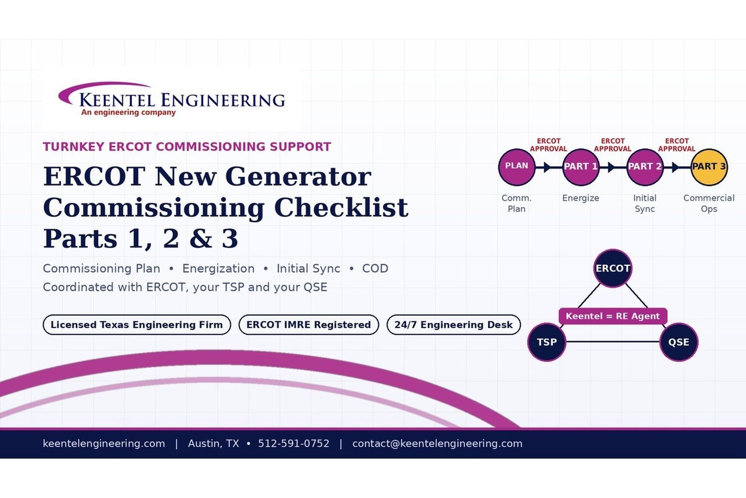
By SANDIP R PATEL
•
September 22, 2026
2026 ERCOT commissioning guide covering the Commissioning Plan, Checklist Parts 1–3, BESS requirements, TSP/QSE coordination, field testing and COD.

By SANDIP R PATEL
•
September 22, 2026
Learn PRC-030-1 R1 event detection requirements for inverter-based resources, SEL platforms, disturbance monitoring, and audit-ready compliance.
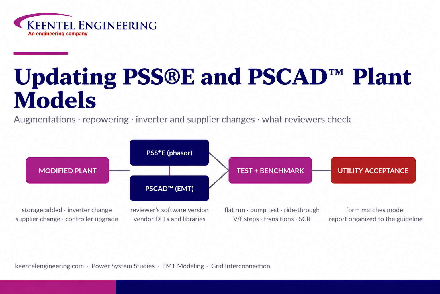
By SANDIP R PATEL
•
September 22, 2026
Learn how PSS®E and PSCAD™ model updates support plant augmentations, repowering, equipment changes, testing, benchmarking, and grid compliance.
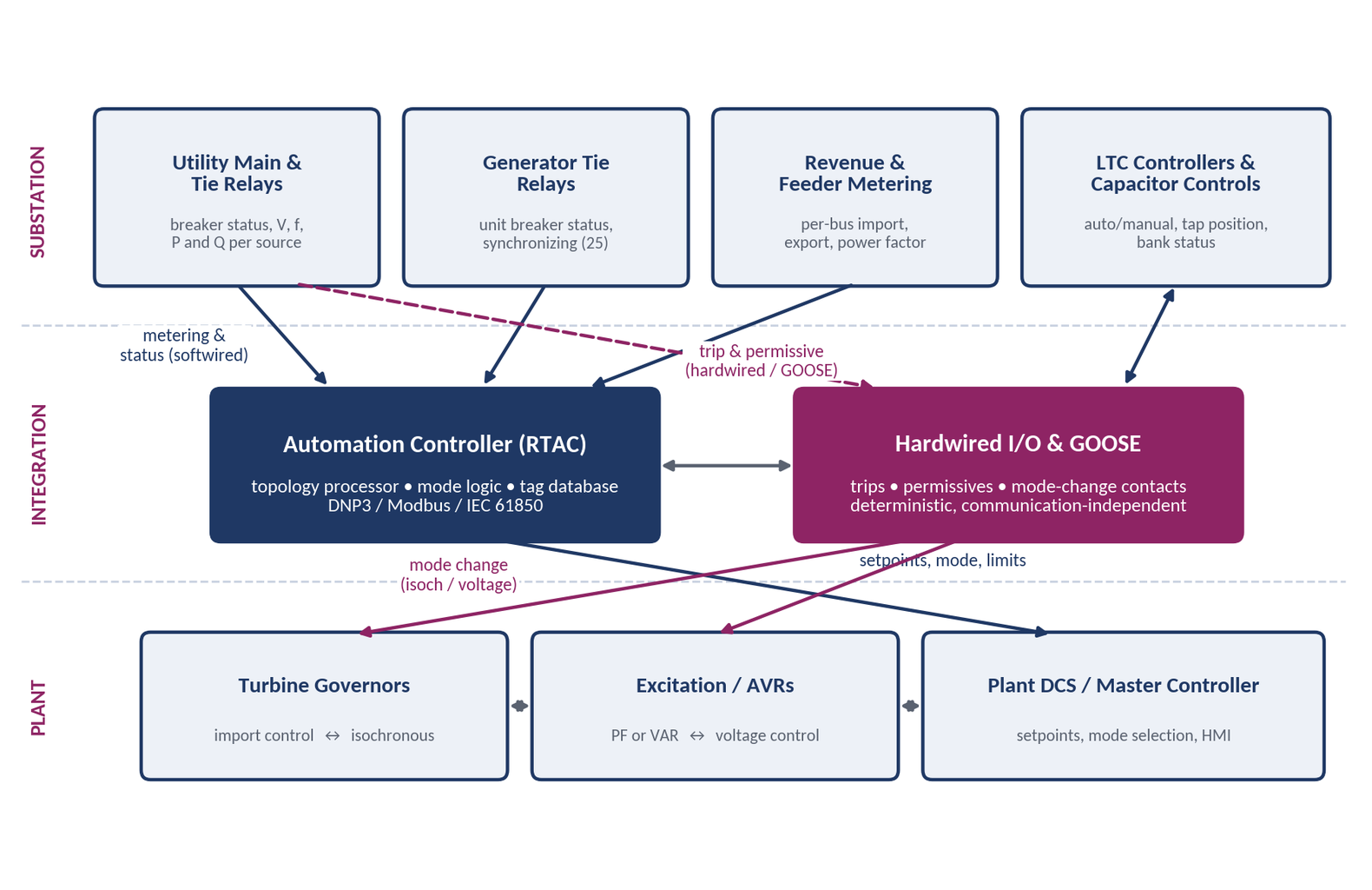
By SANDIP R PATEL
•
September 20, 2026
Learn CHP load following and island detection engineering for campus plants, including protection, controls, power studies, and grid transition design.





